Table of Contents
Advertisement
Advertisement
Table of Contents

Related Manuals for Canon PR-C151


Summary of Contents for Canon PR-C151
- Page 1 DIRECT CARD PRINTER Operation Guide...
-
Page 3: Table Of Contents
Contents Section 1 For your safety a) Before installing ............................2 b) Before turning power ON ......................... 4 c) Before using ..............................5 d) Before moving the equipment ......................... 8 e) Other .................................. 9 f) Prohibited matters ............................9 Section 2 Preparation a) Package contents ............................ - Page 4 Section 4 Operation Panel a) Outline of the Operation Panel ......................... 23 Appearance and composition Function of each part b) Operation of Normal Mode ........................24 Checking "Ready to Print" status Recovering from the Error status Change the Ink Ribbon Clearing the Output Data EXE key print Stopping the continuous printing...
- Page 5 Section 7 Periodical replacement of parts a) Replacing Input Roller ..........................43 b) Replacing Print Head ........................... 44 c) Replacing Fan Filter ............................. 46 Section Basic specification Section Configuration of the equipment Section 10 Trouble and Countermeasure a) Troubles displayed on the operation panel ..................49 Display of trouble on the LCD panel Basic operation to release troubles Trouble shooting...
-
Page 6: For Your Safety
Section 1: For your safety Several illustrations are used in this operation manual to ensure safe operation. The following conventions are used to identify the result caused by the use or operations not following such illustrations. Danger :This indicates that there is a danger of death or serious injury. -
Page 7: A) Before Installing
1 - a) Before installing Caution About environment for installation Do not install in humid and dusty room. It may ○ cause fire and/or electric shock. Do not install the equipments near the ○ heat emitting apparatus such as stove and heater or near the flammables such as curtain. - Page 8 Enough space must be provided around the ● equipments. This is necessary for easy operation as well as for ventilation. If the ventilation opening is closed by obstacle, heat cannot be dissipated and it may cause a fire. ( Place with the clearance as shown in the illustration.
-
Page 9: B) Before Turning Power On
1 - b) Before turning the power ON About power source Do not use any other outlet than following. ○ Do not connect more than one equipment onto one outlet. Otherwise, it may cause a fire and/or electric shock. The specified rating of this equipment is following. -
Page 10: C) Before Using
1 - c) Before using Warning About handling the equipment Do not put anything containing water such ○ as vase etc. on the equipment. If water is spilled, it may cause fire or electric shock. Do not put any metal pieces such as paper ○... - Page 11 If smoke or unusual smell is detected, stop ● using. If it is used as it is, it may cause fire or electric shock. Turn OFF the main switch immediately, plug off the power cord and contact the dealer from whom the equipment was purchased.
- Page 12 Caution About handling of the equipment Do not put any heavy article on the equipment. It may damage the equipment ○ or cause the injury by dropping. Do not use flammable sprays at near the equipment. It may catch fire and ○...
-
Page 13: D) Before Moving The Equipment
1 - d) Before moving the equipment Caution About power source Turn OFF the main switch and plug off the power supply cord from the outlet ● before moving the equipment. Otherwise, it may damage the power cord and cause a fire. To pull off the plug of the power cord, ●... -
Page 14: E) Other
1 - e) Other If the equipment is installed and operated at near TV set or radio, it may cause an interference such as noise or flicker. In such case, use the outlet connected to separate power line and place the equipment as far as possible from them. -
Page 15: A) Package Contents
Section 2: Preparation 2 - a) Package contents Following items are packed in the carton together with the printer. If anything is missing, contact the dealer from whom you have purchased. □ □ Power Supply Cord Empty Bobbin □ □ Cleaning Card Stacker Box □... -
Page 16: B) Consumables
2 - b) Consumables Ink ribbons and cards must be prepared to use this printer. Ink Ribbons The following 2 kinds of ribbons are used for this printer. Name Marking Number of frames Reference (Per roll) Color Dye sublimation type full color w/ resin black + Heat melting black + Overcoat Resin black... -
Page 17: C) Parts To Be Replaced Periodically
2 - c) Parts to be replaced periodically Spare Print Head, Input Rollers and Fan Filter are available for periodic replacement in order to ensure the print quality and long life of machine. Print Head The Print Head comes with the floppy disk which contains the data for best print quality assured. -
Page 18: Input Roller
Input Roller Periodic replacement cycle for the Input Roller is every 40,000 frames if the recommended cards are used and cleaning is done every 2,000 frames. To exchange the Roller, refer the item "Replacing Input Roller" at 7-a). For cleaning the Rollers, refer the item "Input roller" at 6-a). Fan Filter Recommended Replacement period: every 6 months Do not wash with water. -
Page 19: E) Name Of The Parts
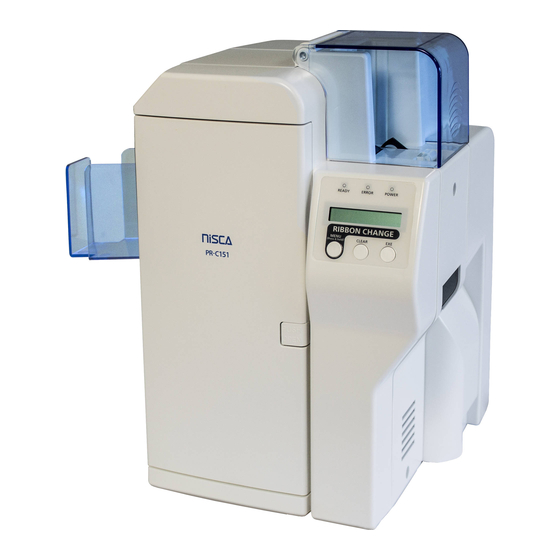
2 - e) Name of the parts Front side of the printer ③ ② ⑤ ⑧ ④ ⑨ ⑦ ① ⑥ ⑩ ①Front Access Cover ②Top Cover ③Rear Cover ④Operation Panel ⑤Card Feeding Unit ⑥Power Switch ⑦Reject Card Exit ⑧Front Cover ⑨Right Cover ⑩Fan Filter - 14 -... - Page 20 Rear side of the printer ⑦ ② ③ ⑥ ④ ⑤ ① ①Power Cord Receptacle ②USB Connector ③Optional Unit Connector ④Ethernet Connector ⑤Left Cover ⑥Exit Box Mount ⑦Eject Card Exit - 15 -...
- Page 21 Front Access Panel ①Input Roller Module ②Ribbon Cartridge Holding Lever ③Manual Rotation Knob ④Ribbon Cartridge - 16 -...
- Page 22 [ MEMO ] - 17 -...
-
Page 23: A) Environment For Installation
Section 3: Installation Caution □ First, please confirm that you have read the Cautions about installation. 3 - a) Environment for installation The equipment can be used in the ambient temperature of 10~35゜C(50~95°F) but to ensure the best performance, temperature range of 20~25゜C(68~77°F) is recommended. Humidity should be 35 - 80% (RH) and without condensation. -
Page 24: D) Connecting The Printer To Computer
3 - d) Connecting the Printer to Computer USB or LAN interface and RS-232C interface (for IC R/W) Description Interface Cable To Control a Printer USB 2.0 Not bundled ① To Control a Printer Ethernet 100BASE-TX (Operation guaranteed) Not bundled ②... -
Page 25: Setting Printer Id
Setting Printer ID There are 16 PRINTER #s. as a specification and each devices must be assigned with different ID numbers. To set the ID numbers for this card printing system, follow the instruction of the system. The default of this Printer is "5". Caution □... - Page 26 Warning □ Do not connect any device other than the specially designated device PR-L151(Model Name : PR5302) which are presented by CANON FINETECH NISCA, to the connector (Non LPS : Limited Power Source) for the options.(Refer to the printer back view in the Section 2, Name of the parts) →Connected device may be damaged.
-
Page 27: E) Power On
3 - e) Power ON Caution □ The electrical rating of power for this printer is alternate power (AC100V-240V .50 Hz or 60Hz). □ Earth must be securely connected for this printer. □ The maximum power consumption of this printer is 120W. Avoid power failure or voltage drop as much as possible. -
Page 28: Operation Panel
Section 4: Operation Panel 4 - a) Outline of the Operation Panel Appearance and composition READY LED ERROR LED POWER LED Ready to Print EXE Key CLEAR Key RIBBON CHANGE / MENU Key Function of each part The functions of LCD and the three keys (Menu, Clear, Exe) are different for Normal Mode ( after the power is turned ON and before entering the User Mode) and for the User Mode. -
Page 29: B) Operation Of Normal Mode
4 - b) Operation of Normal Mode When the power is turned ON, the printer is in Normal Mode. The Power LED (Blue) turns ON and the printer status is shown on the LCD panel. Normal Mode is the mode for printing, and the printer status is shown on the LCD panel. For example, when the printer is waiting to print, "Ready to Print"... -
Page 30: C) Operation Of User Mode
4 - c) Operation of User Mode User Mode is used to set the printer setting for the user environment or to check the printer status. Switching to User Mode 1.Press and hold the MENU key on the Operation Panel as illustrated. The message on the LCD display changes from Ready to Print "Input Command"... -
Page 31: D) Function Of User Mode
4 - d) Functions of User Mode Checking the number of cards used: Card Count Indicates the number of the cards taken-in from the card feeder. It returns to 0 by pressing Clear key. → To be used for the control of card consumption. Total count of the printed frames: Total Count This is a maintenance counter for the accumulated number of the frames printed. -
Page 32: On/Off Of The Error Buzzer: Error Buzzer
Y and M. Correlation of RGB and CMY If there is a customized setting, color tone of CANON FINETECH NISCA default setting and the customized setting can be selected with Gamma0 Select menu. Please ask the dealer for the details. -
Page 33: Setting The System Environment: Printer Status
Setting the System Environment: Printer Status This item must be set according to the Card printing system being used. So, follow the Card printing system instructions for setting. To enter this menu, in order to prevent operational error, follow the instruction on the display and press Clear key and Exe key at the same time. -
Page 34: Interface Settings: Interface Setup
Interface Settings: Interface Setup These parameters must be configured in accordance with the network environment to which the printer is connected. Configure these settings per the guidance provided by your network administrator. To prevent unintended accidental operation, the CLEAR key and EXE key must be pressed simultaneously in accordance with the display to enter this menu. -
Page 35: E) Structure Of User Mode
4 - e) Structure of User Mode ◆ The items shown with □□ are to be set by the Ready to Print User. Default settings is shown by the white letters Removable Ribbon on the black background User Mode ◆ The display surrounded with appears only CLR:Back EXE:Go when the corresponding optional unit is connected... - Page 36 Interface Setup Interface Setup Printer Status Printer Status ① ② Push MENU Key Push MENU Key CLR+EXE:submen CLR+EXE:submen Parallel Print Printer ID (on) □□ □□ Card Eject Face DHCP (Print Face Up) □□ □□ Option Setup IP Address EXE:submenu □□ Return to normal Subnet Mask Mode...
-
Page 37: How To Set Cards And Ribbon
Section 5: How to Set Cards and Ribbon 5 - a) Setting cards Caution □ Do not use the card other than designated by the dealer. → Otherwise, it may not produce the normal print quality and cause trouble on the equipment. □... - Page 38 Caution □ When loading the cards, stack the cards evenly as marked with ○ in the figure below. If it is stacked unevenly as shown with the × mark in the figure below, it may cause "Pick Up Error" or the stack may collapse. - 33 -...
-
Page 39: B) Setting The Ink Ribbon
5 - b) Setting the ink ribbon Caution □ When taking out the ink ribbon cartridge before it becomes empty (while LCD panel displays other than "Ribbon Empty"), press RIBBON CHANGE key and confirm that the head is lifted. → Cartridge cannot be removed with the head at the printing position. The ribbon may be wrinkled or broken if the cartridge is removed forcibly. - Page 40 Release the lock of Ribbon Cartridge and and open as illustrated. Peel off the remaining ribbon from the supply bobbin. Dispose of the take up bobbin with the full used ribbon. Place the now empty supply bobbin in the take up side of the cartridge touse as take up bobbin.
- Page 41 Section 6: Cleaning Clean the rollers and print head regularly to ensure a comfortable working environment. Read the cautions in this manual carefully before the cleaning operation. Caution □ Turn OFF the main switch and pull out the plug of power cord before the cleaning operation. →...
-
Page 42: A) Input Roller
6 - a) Input Roller Before starting this operation, please read the general advice which appears in the beginning part of this section. Remove the Input Roller module as explained in Page 43 and clean in the following procedure. Wet and squeeze a piece of soft cloth with alcohol for cleaning OA equipment and wipe in the direction as illustrated. -
Page 43: B) Cleaning Of The Card Transport Rollers In Flip Turn Block
6 - b) Cleaning of the card transport rollers in Flip Turn Block Before beginning this operation, please read the general advice which appears in the beginning part of this section. ◆ Open the top cover, rotate the whole Flip Turn Module to the angle of easy to clean as using green handle as shown in the figure. -
Page 44: C) Cleaning Of The Print Rollers
6 - c) Cleaning of the Print Rollers Before starting this operation, please read the general advice which appears in the beginning part of this section. Caution □ Turn OFF the main switch and pull out the plug of power cord before the cleaning operation. →... -
Page 45: E) Cleaning Of The Supply Roller
6 - e) Cleaning of the Supply Roller Before starting this operation, please read the general advice which appears in the beginning part of this section. ◆ Wet and squeeze the soft cloth with alcohol for OA equipments and wipe the all surface of the roller in the direction as shown by arrow in the figure below. -
Page 46: F) Cleaning Of The Print Head
6 - f) Cleaning of the Print Head Caution □ The Print Head will be remaining hot when just after Printing. Before starting this operation, make sure that the Print Head module has been cool. □ Turn OFF the main switch and pull out the plug of power cord before the cleaning operation. →... -
Page 47: G) Cleaning Of The Card Transport Roller
6 - g) Cleaning of the card transport roller It is able to clean the card transportation roller automatically, by using a specific cleaning card, and carrying out a cleaning mode. But clean the input roller separately. Prepare a specific cleaning card, and turn the printer power on. →... -
Page 48: Periodical Replacement Of Parts
Section 7: Periodical replacement of parts This printer offers a superb performance for long period with very high reliability. But to maintain the performance, some parts need to be replaced periodically. This means the low running cost. Replacement can be easily done if the operator has basic knowledge or experience of handling electronic machinery. -
Page 49: B) Replacing Print Head
* Make sure the head module is locked firmly by the lever "C" as shown with circle "B". To install the head data First, you have to get the application for the download from CANON FINETECH NISCA homepage through internet addressed at http://ftn.canon/ . Please see the information attached application for the way of installation. - Page 50 Take the wrong operation prevention cover off. 誤 操作 防止 カバ ーを 取り 外し ます 。 ① ② - 45 -...
-
Page 51: C) Replacing Fan Filter
7 - c) Replacing Fan Filter Caution □ Turn OFF the main switch and pull out the plug of power cord before the replacement operation. → Otherwise, an electrical shock or personal injury could result. A figure on right shows a part of back side of the right cover located just below the card hopper. -
Page 52: Section 8 : Basic Specification
Section 8: Basic Specification 1 Printing Method Image Area : Dye Diffusion Thermal Transfer Character Area : Molten Type Thermal Transfer Protective Layer : Molten Type Thermal Transfer system 2 Printing Media PVC Card (Conforms to ISO 7810 , JIS X6301 )or made of other materials with receivable layer on the surface Size : 54.5mm x 85.5mm Thickness : 0.76 +- 10% mm... -
Page 53: Section 9: Configuration Of The Equipment
Section 9: Configuration of the equipment ① Card Supply Unit Picks up a card from the bottom of the stack and feeds to the printer with the Supply Roller. The slot is 1.5 times of the thickness of the card so that the double feeding will not occur. ②... -
Page 54: Trouble And Countermeasure
Section 10: Trouble and Countermeasure 10 - a) Troubles displayed on the operation panel If a trouble occurs, the red lamp on the operation panel turns ON and the nature of the trouble is shown on the LCD panel. In addition to the indication of ribbon empty and card empty, almost all kinds of troubles such as setting of the ribbon type, position of card jam, etc., can be checked with the messages on the LCD panel Display of trouble on the LCD panel If messages which is not listed below appears or the trouble is not released, please contact the dealer. -
Page 55: Trouble Shooting
Trouble shooting Message on LCD Cause/ Countermeasure Ref. ◆ Card is empty. Card Empty → Supply cards. P.32 ○○-○○ □ Card is empty ◆ Front Cover is not closed correctly. Front Cover is → Close the cover positively. Open ○○-○○ □... - Page 56 Trouble shooting Message on LCD Cause/ Countermeasure Ref. ◆ The ribbon typesetting of the printer and the ribbon type actually being used Ribbon Type do not correspond. Incorrect ○○-○○ → Pull out the ribbon cartridge and check the type of the ribbon in P.34 the cartridge.
- Page 57 Trouble shooting Message on LCD Cause/ Countermeasure Ref. ◆ Ink ribbon is not set correctly. Ribbon Wind up → Check whether the ink ribbon is correctly set in the cartridge. P.34 Miss ○○-○○ ◆ Ribbon transport roller is dirty → Clean the roller. P.36 ◆...
-
Page 58: B) Releasing Card Jam
10 - b) Releasing card jam Most of the card jam errors are caused by dirt and stain of the card transport rollers. If the rollers are dirty, card jam error frequently occur. To prevent this, periodic roller cleaning as described in paragraph 6 is recommended. -
Page 59: Block Layout
Block Layout - 54 -... -
Page 60: Card Jam Which Cannot Be Released By Clear Key
Card Jam which cannot be released by Clear key Ref. Message on LCD Cause/Countermeasure Card is not taken into the printer and remaining in the Feeder Block. ◆ → Remove all cards in the Feeder and set them again after separating P.40 Card JAM Feeder the edges of the cards. -
Page 61: C) Troubles Which Are Not Displayed On The Operation Panel
10 - c) Troubles which are not displayed on the operation panel Troubles relating to print image Ref. Problem Cause/Countermeasure ◆ Color drop ◆ If a dust is on the surface of the card when printing, Partial drop or discoloration the part of the dust remains unprinted The dust may disappear after printing. - Page 62 Ref. Problem Cause/Countermeasure ◆ Random bands appears in the direction The print head is heavily stained. ◆ of the card transportation. → Clean the print head. P.41 ◆ More than 20,000 frames are printed. → Replace with a new print head. P.44 ◆...
-
Page 63: Other Troubles
Other troubles Problem Cause/Countermeasure Ref. ◆ Power does not turn ON. ◆ Check the connection of the power cord. → Please call your dealer. ◆ Data cannot be transmitted to ◆ Check that the Printer ID number is not conflicting P.20 the printer. - Page 64 4Y5-8690-040 © CANON FINETECH NISCA INC. 2018...