
Related Manuals for Emerson Rosemount 3051S ERS


Summary of Contents for Emerson Rosemount 3051S ERS
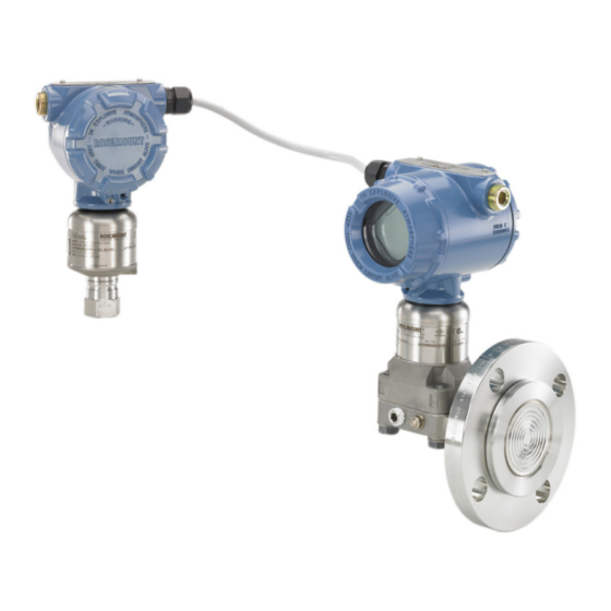
- Page 1 Reference Manual 00809-0100-4804, Rev CB November 2016 ™ Rosemount 3051S Electronic Remote Sensor ™ (ERS) System...
-
Page 3: Table Of Contents
Reference Manual Contents 00809-0100-4804, Rev CB November 2016 1Section 1: Introduction Using this manual ..............1 Product recycling/disposal. - Page 4 Contents Reference Manual 00809-0100-4804, Rev CB November 2016 Additional configuration ............30 3.5.1 Local display .
- Page 5 Reference Manual Contents 00809-0100-4804, Rev CB November 2016 6Section 6: Safety Instrumented Systems Requirements Safety Instrumented Systems (SIS) Certification ........61 6.1.1 Rosemount ERS Systems safety certified identification .
- Page 6 Contents Reference Manual 00809-0100-4804, Rev CB November 2016 B.10 EAC — Belarus, Kazakhstan, Russia ..........119 B.11 Japan .
- Page 7 The products described in this document are NOT designed for nuclear-qualified applications. Using non-nuclear qualified products in applications that require nuclear-qualified hardware or products may cause inaccurate readings. For information on Rosemount nuclear-qualified products, contact your local Emerson Sales Representative. Title Page...
- Page 8 Do not attempt to loosen or remove flange bolts while the Rosemount ERS System is in service. Replacement equipment or spare parts not approved by Emerson for use as spare parts could reduce the pressure retaining capabilities of the transmitter and may render the instrument dangerous.
-
Page 9: Using This Manual
Reference Manual Introduction 00809-0100-4804, Rev CB November 2016 Section 1 Introduction Using this manual The sections in this manual provide information on installing, operating, and maintaining a Rosemount™ ® 3051S Electronic Remote Sensor (ERS)™ System with HART protocol. The sections are organized as follows: Section 2: Installation contains mechanical and electrical installation instructions, and field upgrade... - Page 10 Reference Manual Introduction 00809-0100-4804, Rev CB November 2016 Introduction...
-
Page 11: Overview
3051S Electronic Remote Sensor ™ (ERS) System. A Quick Start Guide is shipped with every Rosemount 3051S ERS Transmitter to describe basic installation, wiring, configuration, and startup procedures. Dimensional drawings for each Rosemount 3051S ERS Transmitter are included in Appendix A: Specifications and Reference Data. -
Page 12: Models Covered
Variety of process connections including flanged, threaded, and hygienic remote diaphragm seals Rosemount 300ERS Housing Kit Upgrade and convert an existing Rosemount 3051S Transmitter into a Rosemount 3051S ERS Transmitter. Easily order replacement housings and electronics for an existing Rosemount ERS System. -
Page 13: Considerations
Measurement performance depends upon proper installation of each transmitter and impulse piping. Mount each Rosemount 3051S ERS Transmitter close to the process and use minimum piping to achieve best performance. Also, consider the need for easy access, personnel safety, practical field calibration, and a suitable environment. -
Page 14: Environmental
Installation Reference Manual 00809-0100-4804, Rev CB November 2016 Cover installation Always ensure a proper seal by installing the housing covers so that metal contacts metal in order to prevent performance degradation due to environmental effects. For replacement cover O-rings, use Rosemount O-rings (part number 03151-9040-0001). - Page 15 The Rosemount ERS System contains additional electrical protection that is inherent to the design. As a result, ERS Systems cannot be used in applications with floating electrical grounds greater than 50 Vdc (such as Cathodic Protection). Consult an Emerson Sales Representative for additional information or considerations on use in similar applications.
-
Page 16: Installation Procedures
) process connection, and the other is mounted on the low-pressure (P ) process connection. An optional remote display and interface may also be included if ordered. 1. Look at the wire-on tag on the Rosemount 3051S ERS Transmitter to identify whether it is configured as the P or P... - Page 17 B4 bracket. Other bracket options are listed in Table When installing a Rosemount 3051S ERS Transmitter to one of the optional mounting brackets, torque the bolts to 125 in-lb. (0,9 N-m). Table 2-1. Mounting Brackets...
- Page 18 A and M. Alloy K-500 Head Marking Bolt installation Only use bolts supplied with the Rosemount 3051S ERS Transmitter or sold by Emerson as spare parts. Use the following bolt installation procedure: 1. Finger-tighten the bolts.
-
Page 19: Process Connections
B. 1.75 in. (44 mm) x 2 D. 1.5 in. (38 mm) x 2 2.5.3 Process connections The process connection size on a Rosemount 3051S ERS Transmitter flange is –18-in NPT. Flange adapters with a –18 NPT to –14 NPT connection are available with the D2 option. Use a plant-approved lubricant or sealant when making the process connections. - Page 20 Rosemount 3051S ERS Transmitter. Use only the O-rings included with the flange adapter for the Rosemount 3051S ERS Transmitter. Failure to install proper fitting flange adapter O-rings may cause process leaks, which can result in death or serious injury.
-
Page 21: Consider Housing Orientation
Reference Manual Installation 00809-0100-4804, Rev CB November 2016 2.5.4 Consider housing orientation Housing rotation The housing can be rotated to improve access to wiring or to better view the LCD display (if ordered). To rotate the housing, perform the following procedure: 1. -
Page 22: Configure Security And Alarm
Configure security and alarm Security switch Changes to the Rosemount ERS System configuration can be prevented with the security (write protect) switch, which is located on the electronics feature board of the Rosemount 3051S ERS Primary Transmitter. See Figure 2-9 for the location of the switch. -
Page 23: Connect Wiring And Power Up
Connect wiring and power up Typical Rosemount ERS System 1. Remove the housing cover labeled “Field Terminals” on both Rosemount 3051S ERS Transmitter. 2. Using the Rosemount ERS Madison Cable (if ordered) or an equivalent 4-wire shielded assembly per the specifications detailed on... - Page 24 Note The transient terminal block is only available as an option on the primary Rosemount 3051S ERS Transmitter. When ordered and installed, a primary Rosemount 3051S ERS Transmitter with the transient terminal block will protect the entire Rosemount ERS Assembly including the secondary Rosemount 3051S ERS Transmitter.
- Page 25 Rosemount ERS System, the power supply used and circuitry common to the transmitters should not have more than 20 ohms of impedance at 1200 Hz. Figure 2-10. Wiring for Typical Rosemount 3051S ERS System PWR/...
- Page 26 Installation Reference Manual 00809-0100-4804, Rev CB November 2016 Figure 2-11. Wiring for Rosemount 3051S ERS System with Remote Display in “Tree” Configuration PWR/ COMM TEST WIRE TO SECONDARY WIRE TO ERS PRIMARY WIRE TO ERS PRIMARY Wiring Legend Wire Terminal connection...
-
Page 27: Grounding
Reference Manual Installation 00809-0100-4804, Rev CB November 2016 Figure 2-12. Wiring for Rosemount 3051S ERS System with Remote Display in “Daisy-Chain” Configuration PWR/ COMM TEST WIRE TO SECONDARY WIRE TO ERS PRIMARY WIRE TO ERS PRIMARY Wiring Legend Terminal connection... - Page 28 Installation Reference Manual 00809-0100-4804, Rev CB November 2016 Figure 2-13. Loop Wire Grounding (Rosemount 3051S ERS Primary Transmitter) A. Positive B. Minimize distance C. Trim shield and insulate D. Insulate shield E. Connect shield back to the power supply negative terminal F.
- Page 29 Reference Manual Installation 00809-0100-4804, Rev CB November 2016 Shield grounding Connect the shield from the Madison Cable assembly to each housing case for the applicable wiring configuration as shown in Figure 2-14. Figure 2-14. Shield Grounding WIRE TO SECONDARY WIRE TO ERS PRIMARY WIRE TO SECONDARY WIRE TO ERS PRIMARY...
-
Page 30: Rosemount Manifolds
The connection is identified by a ground symbol ( Rosemount manifolds The Rosemount 305 Integral Manifold assembles directly to an Rosemount 3051S ERS Transmitter, eliminating the need for the flange. The Rosemount 305 is available in two designs: coplanar (bottom process connections) and traditional (side process connections). -
Page 31: Rosemount 305 Manifold Installation Procedure
2.6.1 Rosemount 305 Manifold installation procedure To install a Rosemount 305 Integral Manifold to a Rosemount 3051S ERS Transmitter: 1. Inspect the PTFE sensor module O-rings. If the O-rings are undamaged, reusing them is recommended. If the O-rings are damaged (if they have nicks or cuts, for example), replace them with new O-rings. -
Page 32: Rosemount 306 Manifold Installation Procedure
2.6.3 Rosemount 306 Manifold installation procedure To install a Rosemount 306 In-Line Manifold to a Rosemount 3051S ERS Transmitter: 1. Place the Rosemount 3051S ERS Transmitter into a holding fixture. 2. Apply appropriate thread paste or tape to the threaded instrument end of the manifold. -
Page 33: Overview
Reference Manual Configuration 00809-0100-4804, Rev CB November 2016 Section 3 Configuration Overview ............... . page 25 Safety messages . -
Page 34: Setting The Loop To Manual
2-10, or Figure 2-11. The Field Communicator or AMS Device Manager may be connected at “PWR/COMM” on the terminal block of the Rosemount 3051S ERS Primary Transmitter, across the load resistor, or at any termination point in the signal loop. ®... -
Page 35: Device Tagging
Reference Manual Configuration 00809-0100-4804, Rev CB November 2016 3.4.1 Device tagging 2, 1, 1, 1 Fast Keys An 8-character free-form text field that can be used to uniquely identify the device. Long tag A 32-character free-form text field that can be used to uniquely identify the device. Long tag is only supported by host systems that are HART Revision 6 or higher. -
Page 36: Variable Mapping
The 4 mA point represents the 0% of span reading, and the 20 mA point represents the 100% of span reading. The analog output range points can also be set using the zero and span adjustment buttons located on the electronics of the Rosemount 3051S ERS Primary Transmitter (see Figure 3-1) and a pressure source. -
Page 37: Alarm And Saturation Levels
38). The ERS System will also drive the output to configured saturation values if the applied pressure goes outside the 4–20 mA range values. The Rosemount 3051S ERS System has three options for configuring the failure mode alarm and saturation levels:... -
Page 38: Additional Configuration
Local display 2, 1, 3 Fast Keys A local display is available as an orderable option on the Rosemount 3051S ERS Primary Transmitter. The display will show a 0–100% scaled bar graph, the selected measurements from Table 3-3, and any diagnostic or error messages. -
Page 39: Multidrop Communication
Reference Manual Configuration 00809-0100-4804, Rev CB November 2016 Note If using an ERS System with the Rosemount 333 HART Tri-Loop, the burst option should be set to “Dyn vars/current.” Burst variable slot definition If either Device vars w/status or Device Variables is selected as the Burst Option, you will need to configure which variables are communicated in Burst Mode. -
Page 40: Scaled Variable
Configuration Reference Manual 00809-0100-4804, Rev CB November 2016 Enabling multidrop configuration To configure an ERS System to be part of a multidrop network: 1. Assign a unique address to the ERS System. For a HART Revision 5 system, the valid address range is 1–15. - Page 41 Reference Manual Configuration 00809-0100-4804, Rev CB November 2016 Figure 3-3. Scaled Variable - Level 4.5 feet Specific Gravity = 0.94 1.5 feet Table 3-5. Scaled Variable Configuration Option Variable Unit Scaled Units Feet (Meter) (Minimum DP) 0 inH O ( 0 mmH Scaled (Level at min.
- Page 42 Configuration Reference Manual 00809-0100-4804, Rev CB November 2016 Direct method The steps required to configure scaled variable for a mass or volume application using the direct method are highlighted below: 1. Enter in a text string (up to five characters: A–Z, -, %, /, *, and “space”) to define the unit of measure for the scaled output.
- Page 43 Reference Manual Configuration 00809-0100-4804, Rev CB November 2016 Table 3-6. Scaled Variable Configuration Options Variable Unit Scaled units GALNS (LITER) Number of scaled points 0 inH O (0 mmH Scaled 15 GALNS (57 LITER) 15 inH O (381 mmH Scaled 30 GALNS (114 LITER) 20 inH O (508 mmH...
- Page 44 Configuration Reference Manual 00809-0100-4804, Rev CB November 2016 Figure 3-5. Supported Tank Shapes for “Tank Formula” Configuration Method A. Horizontal cylinder B. Horizontal bullet C. Vertical bullet D. Vertical cylinder E. Sphere Strapping table method Scaled variable can also be configured by inputting a traditional “Level vs. Volume” strapping table. The steps for using the strapping table method are described below: 1.
-
Page 45: Module Assignments
Field Communicator. Change the P and P module assignments 1. View the neck label on each Rosemount 3051S ERS Transmitter and note the serial number and pressure location (P vs. P ) of the transmitter. 2. Using a Field Communicator, view the serial number and the assigned pressure location for either “Module 1”... -
Page 46: Process Alerts
Reference Manual Configuration 00809-0100-4804, Rev CB November 2016 3.5.6 Process alerts 2, 3 Fast Keys Process alerts allow for the configuration of the ERS System to output a HART message when a parameter (such as the measured DP) exceeds a user-defined operating window. An alert will be communicated to the HART host (such as a Field Communicator or AMS Device Manager) when polled, and on the LCD display of the ERS System. -
Page 47: Hart Menu Trees
Reference Manual Configuration 00809-0100-4804, Rev CB November 2016 HART menu trees Figure 3-7. Overview Home 1 Overview Overview 2 Configure 1 Device Status 3 Service Tools 2 Communications Communications 3 Device Information Variable Mapping 1 Variable Mapping 4 Analog Output 1 Primary Variable 2 Communications Setting 2 2nd Variable... - Page 48 Reference Manual Configuration 00809-0100-4804, Rev CB November 2016 Figure 3-8. Configure Home 1 Overview Configure 2 Configure Guided Setup 1 Guided Setup 3 Service Tools Basic Setup 2 Manual Setup 1 Basic Setup 1 Device Tagging Device Tagging 2 Zero Trim 3 Alert Setup 1 Tag 2 Units of Measure / Damping...
- Page 49 Reference Manual Configuration 00809-0100-4804, Rev CB November 2016 Figure 3-9. Alert Setup, Device Information, and Service Tools Home 1 Overview 2 Configure Configure 3 Service Tools 1 Guided Setup 2 Manual Setup Manual Setup 3 Alert Setup 1 Process Variables 2 Analog Output 3 Scaled Variable 4 Configuration Display...
- Page 50 Reference Manual Configuration 00809-0100-4804, Rev CB November 2016 Configuration...
-
Page 51: Overview
Reference Manual Operation and Maintenance 00809-0100-4804, Rev CB November 2016 Section 4 Operation and Maintenance Overview ............... . page 43 Safety messages . -
Page 52: Calibration
reduce the pressure retaining capabilities of the transmitter and may render the instrument dangerous. Use only bolts supplied or sold by Emerson as spare parts. Improper assembly of manifolds to traditional flange can damage the device. For the safe assembly of the manifold to the transmitter flange, bolts must break the back plane of ... -
Page 53: Phi And Plo Sensor Calibration
Sensor 3, 4, 4, 1 Sensor Each pressure sensor in the Rosemount 3051S ERS System can be individually calibrated. The calibration trim functions for both pressure sensors can be accessed by connecting to the entire ERS System with a ™... -
Page 54: Dp Calibration
The DP calibration function can be used to adjust the calculated DP measurement of the ERS System. For example, a DP zero trim can be performed if the calculated DP of the Rosemount 3051S ERS System has a small offset when the expected output should be “0 DP.”... -
Page 55: Analog Output Trim
Reference Manual Operation and Maintenance 00809-0100-4804, Rev CB November 2016 To perform a two-point DP trim, follow the procedure below: 1. Launch the “Lower DP Trim” function using AMS Device Manager or a Field Communicator. 2. Physically apply the desired low DP value to the entire ERS System. This may require the use of two separate reference pressure devices. -
Page 56: Functional Tests
4-1) on the LCD display, making the system easily identifiable in person. The Find Device function requires a digital display to be installed on the Rosemount 3051S ERS Primary Transmitter. Figure 4-1. “Find Device” Pattern 0 - 0 - 0 - 0 To run the find device function, follow the procedure below: 1. -
Page 57: Field Upgrades And Replacements
Whenever the process flange or flange adapters are removed, visually inspect the PTFE O-rings. Emerson recommends reusing O-rings if possible. If the O-rings show any signs of damage, such as nicks or cuts, they should be replaced. 4.5.2... -
Page 58: Removing The Electronics
4.5.4 Removing the electronics To remove the electronics feature board from a Rosemount 3051S ERS Primary Transmitter: 1. Remove the housing cover opposite the field terminal side. 2. Remove the LCD display (if applicable). Do this by holding in the two clips and pulling outward. This will provide better access to the two screws located on the electronics feature board. -
Page 59: Remove The Supermodule From The Housing
Reference Manual Operation and Maintenance 00809-0100-4804, Rev CB November 2016 4.5.5 Remove the SuperModule from the housing Important To prevent damage to the SuperModule cable, remove the feature board or terminal block assembly with the connector before separating the SuperModule from the housing assembly. 1. -
Page 60: Install The Terminal Block
November 2016 4.5.8 Install the terminal block Rosemount 3051S ERS primary (PlantWeb housing) 1. Gently slide the terminal block into the housing, making sure the pins from the PlantWeb housing properly engage the receptacles on the terminal block. 2. Tighten the captive screws on the terminal block. - Page 61 November 2016 g. If the installation uses a conventional manifold, then install flange adapters on the process end of the manifold using the 1.75-in. flange bolts supplied with the Rosemount 3051S ERS Sensor. Table 4-1. Bolt Installation Torque Values Bolt material...
- Page 62 Operation and Maintenance Reference Manual 00809-0100-4804, Rev CB November 2016 Operation and Maintenance...
-
Page 63: Overview
Reference Manual Troubleshooting 00809-0100-4804, Rev CB November 2016 Section 5 Troubleshooting Overview ............... . page 55 Device overview . - Page 64 Troubleshooting Reference Manual 00809-0100-4804, Rev CB November 2016 Table 5-1. Diagnostic Message Troubleshooting LCD display Host diagnostic Possible problems Recommended actions message message The primary variable has exceeded the range points defined for the 4–20 mA CURR mA Output analog output signal. The analog output is Verify the process conditions and modify the Saturated fixed at the high or low saturation point...
- Page 65 Reference Manual Troubleshooting 00809-0100-4804, Rev CB November 2016 Table 5-1. Diagnostic Message Troubleshooting LCD display Host diagnostic Possible problems Recommended actions message message Verify that both sensors are connected and SNSR No P Module properly wired. Change the pressure Neither of the modules in the ERS System CONFIG Configuration designation of one of the two modules to...
- Page 66 Troubleshooting Reference Manual 00809-0100-4804, Rev CB November 2016 Table 5-2. Rosemount ERS System Troubleshooting Symptom Corrective actions • Verify power is applied to “+” and “-” PWR/COMM terminals on the ERS primary unit • Check power wires for reversed polarity The mA output of the Rosemount ERS System is zero •...
-
Page 67: Measurement Quality Status
To expedite the return process outside of the United States, contact the nearest Rosemount representative. Within the United States, call the Emerson Instrument and Valves Response Center using the 1-800-654-RSMT (7768) toll-free number. This center, available 24 hours a day, will assist you with any needed information or materials. - Page 68 OSHA, a copy of the required Material Safety Data Sheet (MSDS) for each hazardous substance identified must be included with the returned goods. Emerson Instrument and Valves Response Center representatives will explain the additional information and procedures necessary to return goods exposed to hazardous substances.
-
Page 69: Safety Instrumented Systems (Sis) Certification
Maximum ERS cable length for SIS certification is 200 feet (60.96 m). Cable must also meet the specifications from “Rosemount 3051S ERS System cable specifications” on page 6.1.2 Installation in SIS applications Installations are to be performed by qualified personnel. No special installation is required in addition to the standard installation practices outlined in “Connect wiring and power up”... -
Page 70: Configuring In Sis Applications
Safety Instrumented Systems Reference Manual 00809-0100-4804, Rev CB November 2016 6.1.3 Configuring in SIS applications ® Use any HART -capable configuration tool to communicate with and verify configuration of the Rosemount ERS System. Note Transmitter output is not safety-rated during the following; configuration changes, multidrop, and loop test. -
Page 71: Rosemount 3051S Sis Operation And Maintenance
Reference the FMEDA Report for percent of possible DU failures in the device. FMEDA report can be found at Emerson.com/Rosemount/Safety. Required tools: Field Communicator and pressure calibration equipment. 1. Bypass the safety function and take appropriate action to avoid a false trip. - Page 72 Emerson.com/Rosemount/Safety-Web-Apps/Report. All product repair and part replacement should be performed by qualified personnel. Rosemount 3051S ERS SIS reference The Rosemount 3051S ERS must be operated in accordance to the functional and performance specifications provided in Appendix A: Specifications and Reference Data.
-
Page 73: Aappendix A: Specifications And Reference Data
Specifications and Reference Data Reference Manual November 2016 00809-0100-4804, Rev CB Appendix A Specifications and Reference Data Performance specifications ............page 65 Functional specifications . - Page 74 Terms and Conditions of Sale, Document 63445, Rev G (10/06). Rosemount Ultra and Enhanced Sensors in an ERS configuration have a limited warranty of fifteen (15) years from date of shipment. All other provisions of Emerson standard limited warranty remain the same.
- Page 75 Specifications and Reference Data Reference Manual November 2016 00809-0100-4804, Rev CB Ambient temperature effects per 50 °F (28 °C) Coplanar gage sensor (Rosemount 3051SAM_ _G) Ultra Classic ±(0.009% URL + 0.025% Span) from 1:1 to 10:1 ±(0.0125% URL + 0.0625% Span) from 1:1 to 5:1 Range 2-5 ±(0.018% URL + 0.05% Span) from >10:1 to 200:1 ±(0.025% URL + 0.125% Span) from >5:1 to 100:1...
-
Page 76: Functional Specifications
Use “Classic” specification regardless of specified performance class. DP span considerations Consult with your Emerson Sales Representative or Instrument Toolkit when considering a Rosemount 3051S ERS System for use on applications beyond 100:1 rangedown (operating pressure/DP span). Specifications and Reference Data... -
Page 77: Service
External power supply required (16–42.4 Vdc with no load) 16 16.74 42.4 Voltage (Vdc) Overpressure limits Rosemount 3051S ERS Sensor Modules can withstand the following limits without damage Coplanar gage sensor Coplanar absolute sensor In-Line gage sensor In-Line absolute sensor... -
Page 78: Process Temperature Limits
Reference Manual Specifications and Reference Data November 2016 00809-0100-4804, Rev CB A.2.5 Process temperature limits Table A-4. Gage/Absolute Sensor Coplanar gage/absolute sensor In-Line gage sensor/absolute sensor (Rosemount 3051SAM_ _G, Rosemount (Rosemount 3051SAM_ _T, Rosemount Configuration 3051SAM_ _A) 3051SAM_ _E) (1)(2) Silicone fill fluid –40 to 250 °F (–40 to 121 °C) (1)(2) -
Page 79: Physical Specifications
Figure A-1. Thermal Optimizer with D.C. Silicone 704 Temperature Limits A.3.1 Maximum cable length For maximum cable lengths, see “Rosemount 3051S ERS System cable specifications” on page For SIS maximum lengths see “Rosemount ERS Systems safety certified identification” on page A.3.2 Electrical connections... -
Page 80: Process Wetted Parts
Reference Manual Specifications and Reference Data November 2016 00809-0100-4804, Rev CB A.3.4 Process wetted parts A.3.5 Non-wetted parts Process isolating diaphragms Electronics housing Coplanar gage/absolute sensor (Rosemount 3051SAM_ _G, Low-copper aluminum alloy or CF-8M (Cast 316 SST) Rosemount 3051SAL _ _A) ®... -
Page 81: Dimensional Drawings
4.20 4.55 (107) (116) 8.53 (217) 9.63 (245) 6.44 (164) Dimensions are in inches (millimeters). Figure A-3. Rosemount 3051S ERS Coplanar Sensor and Flange with Junction Box Housing Front view Side view 4.20 3.45 (107) (88) 8.53 (217) 9.63 (245) 6.44... - Page 82 9.26 (235) 1.63 (41) 2.13 (54) 3.40 1.10 (86) (28) Dimensions are in inches (millimeters). Figure A-5. Rosemount 3051S ERS Coplanar Sensor with Traditional Flange and Junction Box Housing Front view Side view 3.45 (88) 9.26 (235) 1.10 3.40 (28) (86) Dimensions are in inches (millimeters).
- Page 83 Front view Side view 5.17 (131) 4.20 (107) 4.51 (115) 8.04 (204) Dimensions are in inches (millimeters). Figure A-7. Rosemount 3051S ERS In-Line Sensor with Junction Box Housing Front view Front view 3.45 4.20 (88) (107) 8.04 (204) Dimensions are in inches (millimeters).
- Page 84 Reference Manual Specifications and Reference Data November 2016 00809-0100-4804, Rev CB Figure A-8. Coplanar Mounting Configurations (B4 Bracket) Pipe mount Panel mount Front view Front view Front view 4.55 2.58 (116) (66) 6.15 (156) 2.81 (71) 3.54 4.72 6.25 (120) (90) (159) Dimensions are in inches (millimeters).
- Page 85 Specifications and Reference Data Reference Manual November 2016 00809-0100-4804, Rev CB Figure A-10. In-Line Mounting Configurations (B4 Bracket) Pipe mount Panel mount Front view Side view 2.58 4.55 (116) (66) 6.15 2.81 (156) 6.15 (71) 6.25 3.08 (159) (78) 4.72 (120) 6.90 (175) Dimensions are in inches (millimeters).
- Page 86 4.20 (131) (107) 9.63 (245) 6.44 (164) ½– 14 NPT (2) Dimensions are in inches (millimeters). Figure A-13. Rosemount 3051S ERS Measurement Transmitter–In Line Style 5.17 (131) 3.45 4.20 (88) (107) 4.51 (115) 8.04 (204) Dimensions are in inches (millimeters).
- Page 87 Specifications and Reference Data Reference Manual November 2016 00809-0100-4804, Rev CB ™ (1)(2) Figure A-14. Rosemount 3051S Scalable Level Transmitter with FF Seal Coplanar style In-Line style 5.17 4.20 5.17 (107) (131) (131) 4.51 4.20 (114) (107) 8.04 8.57 (204) (217,7) 1.50 (38)
- Page 88 Reference Manual Specifications and Reference Data November 2016 00809-0100-4804, Rev CB Figure A-16. Rosemount 3051S Scalable Level Transmitter with RF Seal Coplanar style In-Line style 4.20 5.21 5.17 (107) (132) (131) 4.51 (107) (115) 8.04 (204) 8.57 (218) 1.50 (38) 3.62 (92) + Direct Mount...
- Page 89 Specifications and Reference Data Reference Manual November 2016 00809-0100-4804, Rev CB Figure A-18. Rosemount 3051S Scalable Level Transmitter with SS Seal Coplanar style In-Line style 5.17 4.20 5.17 (131) (107) (131) 4.51 4.20 (115) (107) 8.04 (204) 8.57 (218) 1.50 (38) 3.62 (92) + Direct Mount...
-
Page 90: Ordering Information
Reference Manual Specifications and Reference Data November 2016 00809-0100-4804, Rev CB A.5 Ordering information Rosemount 3051SAM Transmitter for ERS Applications Coplanar and In-Line sensor module platforms Variety of process connections including threaded NPT, flanges, manifolds, and Rosemount 1199 Remote Seals ... - Page 91 Specifications and Reference Data Reference Manual November 2016 00809-0100-4804, Rev CB Table A-6. Rosemount 3051SAM Scalable Advanced Measurement Transmitter for ERS Applications Ordering Information H The Standard offering represents the most common options. The starred options (H) should be selected for best delivery. The Expanded offering is subject to additional delivery lead time.
- Page 92 Reference Manual Specifications and Reference Data November 2016 00809-0100-4804, Rev CB Table A-6. Rosemount 3051SAM Scalable Advanced Measurement Transmitter for ERS Applications Ordering Information H The Standard offering represents the most common options. The starred options (H) should be selected for best delivery. The Expanded offering is subject to additional delivery lead time.
- Page 93 Specifications and Reference Data Reference Manual November 2016 00809-0100-4804, Rev CB Table A-6. Rosemount 3051SAM Scalable Advanced Measurement Transmitter for ERS Applications Ordering Information H The Standard offering represents the most common options. The starred options (H) should be selected for best delivery. The Expanded offering is subject to additional delivery lead time.
- Page 94 Reference Manual Specifications and Reference Data November 2016 00809-0100-4804, Rev CB Table A-6. Rosemount 3051SAM Scalable Advanced Measurement Transmitter for ERS Applications Ordering Information H The Standard offering represents the most common options. The starred options (H) should be selected for best delivery. The Expanded offering is subject to additional delivery lead time.
- Page 95 Specifications and Reference Data Reference Manual November 2016 00809-0100-4804, Rev CB Table A-6. Rosemount 3051SAM Scalable Advanced Measurement Transmitter for ERS Applications Ordering Information H The Standard offering represents the most common options. The starred options (H) should be selected for best delivery. The Expanded offering is subject to additional delivery lead time.
- Page 96 Tantalum diaphragm material is only available with Pressure Sensor/Module code G. “Assemble to” items are specified separately and require a completed model number. Consult an Emerson representative for performance specifications. Maxium cable distance for SIS installations. See “Rosemount ERS Systems safety certified identification” on page 61 for more information.
- Page 97 Specifications and Reference Data Reference Manual November 2016 00809-0100-4804, Rev CB Rosemount 3051SAL Level Transmitter for ERS Applications Integrated transmitter and remote seal in a single model number Variety of process connections including flanged, threaded, and hygienic remote seals ...
- Page 98 Reference Manual Specifications and Reference Data November 2016 00809-0100-4804, Rev CB Table A-7. Rosemount 3051SAL Scalable Advanced Level Transmitter for ERS Applications Ordering Information H The Standard offering represents the most common options. The starred options (H) should be selected for best delivery. The Expanded offering is subject to additional delivery lead time.
- Page 99 Specifications and Reference Data Reference Manual November 2016 00809-0100-4804, Rev CB Table A-7. Rosemount 3051SAL Scalable Advanced Level Transmitter for ERS Applications Ordering Information H The Standard offering represents the most common options. The starred options (H) should be selected for best delivery. The Expanded offering is subject to additional delivery lead time.
- Page 100 Reference Manual Specifications and Reference Data November 2016 00809-0100-4804, Rev CB Table A-7. Rosemount 3051SAL Scalable Advanced Level Transmitter for ERS Applications Ordering Information H The Standard offering represents the most common options. The starred options (H) should be selected for best delivery. The Expanded offering is subject to additional delivery lead time.
- Page 101 Specifications and Reference Data Reference Manual November 2016 00809-0100-4804, Rev CB Table A-7. Rosemount 3051SAL Scalable Advanced Level Transmitter for ERS Applications Ordering Information H The Standard offering represents the most common options. The starred options (H) should be selected for best delivery. The Expanded offering is subject to additional delivery lead time.
- Page 102 Reference Manual Specifications and Reference Data November 2016 00809-0100-4804, Rev CB Table A-7. Rosemount 3051SAL Scalable Advanced Level Transmitter for ERS Applications Ordering Information H The Standard offering represents the most common options. The starred options (H) should be selected for best delivery. The Expanded offering is subject to additional delivery lead time.
- Page 103 Specifications and Reference Data Reference Manual November 2016 00809-0100-4804, Rev CB Direct mount seals for Rosemount 3051SAL Flush Flanged (FF) Seal Most common seal Good for use in general applications Easy installation on flanged connections ranging from 2-in. (DN 50) to 4-in. (DN 100) ...
- Page 104 Reference Manual Specifications and Reference Data November 2016 00809-0100-4804, Rev CB Table A-8. FF Flush Flanged Seal Ordering Information H The Standard offering represents the most common options. The starred options (H) should be selected for best delivery. The Expanded offering is subject to additional delivery lead time. Flushing connection quantity and size None -18 NPT flushing connection...
- Page 105 Specifications and Reference Data Reference Manual November 2016 00809-0100-4804, Rev CB Extended Flanged (EF) Seal Good for use in viscous applications with plugging issues Seal diaphragm installed flush with inner tank wall to prevent process plugging Easy installation on 3-in. (DN 80) and 4-in. (DN 100) flanged connections ...
- Page 106 Reference Manual Specifications and Reference Data November 2016 00809-0100-4804, Rev CB Table A-9. EF Extended Flanged Seal Ordering Information H The Standard offering represents the most common options. The starred options (H) should be selected for best delivery. The Expanded offering is subject to additional delivery lead time. Options (include with selected model number) Cold temperature remote seal applications...
- Page 107 Specifications and Reference Data Reference Manual November 2016 00809-0100-4804, Rev CB Remote Flanged (RF) Seal Designed to improve performance on smaller process connections Easy installation on flanged connections ranging from 1- to 1.5-in. (DN 50–DN 40) Lower housing/flushing ring required ...
- Page 108 Reference Manual Specifications and Reference Data November 2016 00809-0100-4804, Rev CB Table A-10. RF Remote Flanged Seal Ordering Information H The Standard offering represents the most common options. The starred options (H) should be selected for best delivery. The Expanded offering is subject to additional delivery lead time. Number of flushing connections One 1 –18 NPT flushing connection...
- Page 109 Specifications and Reference Data Reference Manual November 2016 00809-0100-4804, Rev CB Remote Threaded (RT) Seal For use with threaded process connections ( -18 to 1–11.5 NPT) Rated for use in high-pressure applications (up to 2500 PSI) Optional flushing connections available ...
- Page 110 Reference Manual Specifications and Reference Data November 2016 00809-0100-4804, Rev CB Table A-11. RT Remote Threaded Seal Ordering Information H The Standard offering represents the most common options. The starred options (H) should be selected for best delivery. The Expanded offering is subject to additional delivery lead time. Options (include with selected model number) Remote seal diaphragm thickness...
- Page 111 Specifications and Reference Data Reference Manual November 2016 00809-0100-4804, Rev CB Hygienic Tri Clamp (SC) Seal Good for use in hygienic applications Easy installation on Tri-Clover style Tri Clamp connections (1 -in. to 3-in.) Conforms to 3-A standard 74-03 ...
- Page 112 Reference Manual Specifications and Reference Data November 2016 00809-0100-4804, Rev CB Hygienic Tank Spud (SS) Seal Commonly used in hygienic level applications Seal diaphragm installed flush with inner tank wall Conforms to 3-A standard 74-03 Table A-13. SS Hygienic Tank Spud Seal Ordering Information H The Standard offering represents the most common options.
- Page 113 Specifications and Reference Data Reference Manual November 2016 00809-0100-4804, Rev CB Table A-13. SS Hygienic Tank Spud Seal Ordering Information H The Standard offering represents the most common options. The starred options (H) should be selected for best delivery. The Expanded offering is subject to additional delivery lead time. Additional options Surface finish certification Surface finishing certification for hygienic remote seals...
- Page 114 Reference Manual Specifications and Reference Data November 2016 00809-0100-4804, Rev CB Rosemount 300 ERS Transmitter Housing Kit Housing kit for Rosemount 3051SAM and 3051SAL ERS Transmitters Upgrade an existing Rosemount 3051S Transmitter to an ERS configuration Table A-14. Rosemount 300 ERS Transmitter Housing Kit Ordering Information H The Standard offering represents the most common options.
- Page 115 Specifications and Reference Data Reference Manual November 2016 00809-0100-4804, Rev CB Table A-14. Rosemount 300 ERS Transmitter Housing Kit Ordering Information H The Standard offering represents the most common options. The starred options (H) should be selected for best delivery. The Expanded offering is subject to additional delivery lead time.
- Page 116 Reference Manual Specifications and Reference Data November 2016 00809-0100-4804, Rev CB Table A-14. Rosemount 300 ERS Transmitter Housing Kit Ordering Information H The Standard offering represents the most common options. The starred options (H) should be selected for best delivery. The Expanded offering is subject to additional delivery lead time.
-
Page 117: Spare Parts
Example model number: 300ERSP1AAM5 Electronics board (ERS primary unit only) Rosemount 3051S ERS electronics feature board kit 03151-9028-0001 Rosemount 3051S ERS electronics feature board kit for remote display housing 03151-9028-0002 LCD display (ERS primary unit only) LCD display with extended aluminum housing cover... - Page 118 Reference Manual Specifications and Reference Data November 2016 00809-0100-4804, Rev CB Flange adapter kits (each kit contains adapter, bolts, and O-rings [qty 2]) CS bolts, glass filled PTFE O-rings SST adapters 03031-1300-0002 Cast C-276 adapters 03031-1300-0003 Cast Alloy 400 adapters 03031-1300-0004 Ni plated CS adapters 03031-1300-0005...
- Page 119 Specifications and Reference Data Reference Manual November 2016 00809-0100-4804, Rev CB Mounting brackets Mounting brackets for coplanar flange B4 bracket, SST, 2-in. pipe mount, SST bolts 03151-9270-0001 Mounting brackets for in-line sensor module B4 bracket, SST, 2-in. pipe mount, SST bolts 03151-9270-0002 Mounting brackets Mounting brackets for traditional flange...
- Page 120 Reference Manual Specifications and Reference Data November 2016 00809-0100-4804, Rev CB 150 ft. (45,72 m) of Electronic Remote Sensors cable (gray color) 03151-9101-0150 200 ft (60,96 m) of Electronic Remote Sensors cable (gray color) 03151-9101-0200 225 ft (68,58 m) of Electronic Remote Sensors cable (gray color) 03151-9101-0225 300 ft (91,44 m) of Electronic Remote Sensors cable (gray color) 03151-9101-0300...
-
Page 121: European Directive Information
Quick Start Guide. The most recent revision of the EU Certificate: 3012350 Declaration of Conformity can be found at Standards: FM Class 3600 – 2011, FM Class 3610 – 2010, FM Emerson.com/Rosemount. ® Class 3611 – 2004, FM Class 3810 – 2005, NEMA 250 – 2003 Markings: IS CL I, DIV 1, GP A, B, C, D;... -
Page 122: Canada
Reference Manual Product Certifications November 2016 00809-0100-4804, Rev CB Special Condition for Safe Use (X): Temperature class Process temperature 1. The Rosemount 3051S/3051S-ERS Pressure Transmitter contains aluminum and is considered to constitute a –60 °C to +70 °C potential risk of ignition by impact or friction. Care must be –60 °C to +80 °C taken into account during installation and use to prevent –60 °C to +120 °C... -
Page 123: International
Product Certifications Reference Manual November 2016 00809-0100-4804, Rev CB B.7 International Parameters FISCO IECEx Flameproof and Dust Voltage U 17.5 V Certificate: IECEx KEM 08.0010X (Flameproof) Standards: IEC 60079-0:2011, IEC 60079-1: 2007, IEC Current I 380 mA 60079-26:2006 (3051SFx models with RTD are Power P 5.32 W certified to IEC 60079-0:2004) -
Page 124: Brazil
Reference Manual Product Certifications November 2016 00809-0100-4804, Rev CB 3. It is a condition of manufacture that only the apparatus fitted with housing, covers and sensor module housing made out SuperModule 300 mA 1.0 W 30 nF of stainless steel are used in Group I applications. 3051S...A;... -
Page 125: China
Product Certifications Reference Manual November 2016 00809-0100-4804, Rev CB Special Conditions for Safe Use (X): Special Conditions for Safe Use (X): 1. The device contains a thin wall diaphragm. Installation, 1. Only the pressure transmitters, consisting of 3051SC Series, maintenance and use shall take into account the 3051ST Series, 3051SL Series and 300S Series, are certified. - Page 126 Reference Manual Product Certifications November 2016 00809-0100-4804, Rev CB 12. When installation, use and maintenance of transmitter, 3. Intrinsically safe parameters: observe following standards: GB3836.13-1997 “Electrical apparatus for explosive gas atmospheres Part 13: Repair and overhaul for apparatus used in explosive gas atmospheres” GB3836.15-2000 “Electrical apparatus for explosive gas atmospheres Part 15: Electrical installations in hazardous area (other than mines)”...
-
Page 127: Eac - Belarus, Kazakhstan, Russia
Product Certifications Reference Manual November 2016 00809-0100-4804, Rev CB B.13 Combinations 3. Cable glands, conduit or blanking plugs, certified by NEPSI with Ex e or Ex n protection type and IP66 degree of Combination of E1, I1, N1, and ND protection provided by enclosure, should be used on external connections and redundant cable entries. - Page 128 Reference Manual Product Certifications November 2016 00809-0100-4804, Rev CB Product Certifications...
- Page 130 +65 6777 0947 www.Emerson.com/en-us/Terms-of-Use Enquiries@AP.EmersonProcess.com The Emerson logo is a trademark and service mark of Emerson Electric Co. PlantWeb, Scalable, AMS, Tri-Loop, THUM, SuperModule, Electronic Remote Sensor (ERS) System, Coplanar, Scalable, Rosemount, and Rosemount logotype are Middle East and Africa Regional Office trademarks of Emerson.