Ironman Fitness Gravity 4000 Owner's Manual
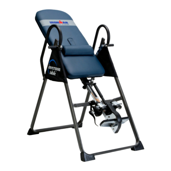
Inversion table
Hide thumbs
Also See for Gravity 4000:
- Owner's manual (20 pages) ,
- Owner's manual (20 pages) ,
- Owner's manual (25 pages)
Table of Contents
Advertisement
Advertisement
Table of Contents

Related Manuals for Ironman Fitness Gravity 4000


Summary of Contents for Ironman Fitness Gravity 4000
- Page 1 5402.6-060117...
- Page 2 PLEASE DO NOT RETURN THIS PRODUCT TO THE STORE. STOP. Contact customer service if you have any questions regarding assembly or proper operation of the machine. Email us at: Service@paradigmhw.com Or call us at: 1-844-641-7922 Hours: 8:00 am to 5:00 pm (PST) Daily...
-
Page 3: Table Of Contents
TABLE OF CONTENTS SERVICE ------------------------------------------------------------------------- LABEL PLACEMENT --------------------------------------------------------- IMPORTANT SAFETY GUIDELINES ------------------------------------- OVERVIEW DRAWING ------------------------------------------------------- PARTS LIST ---------------------------------------------------------------------- HARDWARE & TOOLS PACK----------------------------------------------- ASSEMBLY ----------------------------------------------------------------------- OPERATION & ADJUSTMENTS -------------------------------------------- STORAGE & TROUBLESHOOTING --------------------------------------- WARRANTY ---------------------------------------------------------------------- PART REQUEST FORM -------------------------------------------------------... -
Page 4: Service
SERVICE IMPORTANT: FOR NORTH AMERICA ONLY For damaged or defective product, questions, replacement parts or any other service support, please contact our customer service department (8:00 AM - 5:00 PM Pacific Standard Time, Daily) by the below methods: For The Best Service, please Email: service@paradigmhw.com Response Time: 1-2 Business Days Emailing us with the information above will be the best method to receive a response during... -
Page 5: Label Placement
LABEL PLACEMENT WARNING AVERTISSEMENT Please Keep All Body Parts, S'il vous plaît garder toutes les Hair, Loose Clothing, and parties du corps, les cheveux, Jewelry away from all moving les vêtements amples, et jewlery parts. loin de toutes les pièces mobiles... -
Page 6: Important Safety Guidelines
IMPORTANT SAFETY GUIDELINES Read all instructions before using the Inversion Table. When using an Inversion table, basic precautions should always be followed, including the following: WARNING - To reduce the risk of injury to persons: Make sure your equipment is correctly assembled before you use it. Be sure all screws, nuts, and bolts are tightened prior to use. - Page 7 IMPORTANT SAFETY GUIDELINES Do not use this equipment if you have any of the following conditions or ailments: • Pregnancy • Extreme obesity • Middle ear infection • Hiatus hernia or Ventral hernia • Glaucoma, retinal detachment or conjunctivitis • Use of anticoagulants including Aspirin in high doses.
-
Page 8: Overview Drawing
OVERVIEW DRAWING... -
Page 9: Parts List
PARTS LIST No. Description No. Description Front U-Frame Loop Strap Rear U-Frame Strap Lock Adjustable Boom Foam Bed Bed Frame Foam Grip Pivot Arm Protective Cover Adjustable Lock Plate Hex Head Bolt M8x23 Steel Heel Holder Bracket Front Plastic Cover Right Folding Arm 40L Left Plastic Cover Rear Rod... - Page 10 PARTS LIST No. Description No. Description Bolt M6x30 Bolt M5x10 Spacer Ø22x16.8 Bolt M8x 50 Screw ST4.2x12 Pivot Arm Ring Screw ST4.8x20 Phillips head screw M4x25 Shaft Nut Ø8...
-
Page 11: Hardware & Tools Pack
HARDWARE & TOOLS PACK... -
Page 12: Assembly
ASSEMBLY Tool: Multi Hex Tool with Phillips Screwdriver Step 1: 1.1 Stand up the base of the machine by separating the Front and Rear U-Frames (1, 2). Pull the Front and Rear U-Frames (1, 2) apart from each other. Push down on the middle of the Folding Arms (8) until the frames are fully locked down. - Page 13 ASSEMBLY (55) Nut Cap 2 PCS Step 2: 2.1 Install a Nut Cap (55) onto the Lock Nuts (15). Slide a Protective Cover (37) on to each side of the base as shown. Pull down on the Protective Covers (37) until the bottom of the covers are slightly lower than the Folding Arms (8).
- Page 14 ASSEMBLY Step 4: 4.1 Mount the Bed Frame (4) to the Rear U-Frame (2) by inserting the ends of the Pivot Arms (5) into the channels on the plates. The slotted portion of the rollers on the end of the Pivot Arms (5) should be inserted into the channels on the plates.
- Page 15 ASSEMBLY Step 6: 6.1 Pull out AND HOLD the Large Spring Knob (18) and slide the Adjustable Boom (3) into the square bracket on the bottom of the Bed Frame (4) as shown. Slide the Adjustable Boom (3) to the desired height. 6.2 Lock the Adjustable Boom (3) in place by releasing the Large Spring Knob (18) and sliding the Adjustable Boom (3) up or down slightly until the Large Spring Knob (18) "POPS"...
- Page 16 ASSEMBLY Tool: Multi Hex Tool with Phillips Screwdriver Hex Wrench Step 7: 7.1 Attach the top end of the Handlebar (29) onto the Rear U-Frame (2) and Pivot Arm Ring (72) with one Hex Head Bolt (38), one Lock Nut (15), and two Washers (13). Attach the bottom end of the Handlebar (29) onto the Rear U-Frame (2) with one Hex Head Bolt (43), one Lock Nut (15), and two Washers (13).
-
Page 17: Front U-Frame
ASSEMBLY Step 8: 8.1 Attach the Nylon Strap (32) to the Strap Lock (34) by inserting the end of the Nylon Strap (32) up through the bottom of the Strap Lock (34). Loop the Nylon Strap (32) over the Pre-assembled Loop Strap (33) and down through the Strap Lock (34). - Page 18 ASSEMBLY Step 10: 10.1 Insert the Velcro strap on the Foam Bed (35) to the Lumbar Pad (47) and secure the Lumbar Pad (47) onto the Foam bed (35).
-
Page 19: Operation & Adjustments
OPERATIONS & ADJUSTMENTS Incorrect Correct Make sure the pivot arm is inserted all the way The slot of the Pivot arm is NOT aligned into the slot. When the Pivot arm is aligned correctly. The pivot arm must be inserted correctly in the groove of the curved slot the all the way into the curved slot. -
Page 20: Adjustable Boom
OPERATIONS & ADJUSTMENTS THE STRAP SHORTEN LENGTHEN ADJUSTING THE STRAP A nylon strap has been included to restrict the degree of inversion. This strap can be adjusted to different lengths to allow for a greater or lesser degree of inversion. To lengthen the Nylon Strap (32) feed the top end of Nylon Strap (32) into the strap lock, and pull on the lower end of the strap. -
Page 21: Pivot Arm
OPERATIONS & ADJUSTMENTS PIVOT ARMS The Pivot Arms (5) can be adjusted to allow for a greater or lesser degree of inversion. To adjust the Pivot Arms (5) simply pull out on them until the post is out of the hole, slide them up or down to the desired holes. -
Page 22: Handlebar
OPERATIONS & ADJUSTMENTS SUGGESTIONS FOR USE Begin slowly: invert only 15~20 degrees to begin with. Stay inverted only as long as you are comfortable. Return upright slowly if you feel uncomfortable. Make gradual changes: increase the angle only if it is comfortable. Increase the angles only a few degrees at a time. -
Page 23: Storage & Troubleshooting
STORAGE & TROUBLESHOOTING For your convenience, the inversion table can be folded down to place against a wall, under a bed, or in a storage area. Any other servicing not described in this manual should be performed ONLY by an authorized service representative. -
Page 24: Warranty
WARRANTY MANUFACTURER’S LIMITED WARRANTY Paradigm Health & Wellness warrants to the original purchaser that this product is free from defects in material and workmanship when used for the purpose intended, under the conditions that it has been installed and operated in accordance with Paradigm’s Owner’s Manual. -
Page 25: Part Request Form
PARTS REQUEST FORM Paradigm Health & Wellness, Inc. EMAIL THIS FORM WITH YOUR RECEIPT OF PURCHASE TO Service@paradigmhw.com NAME:_____________________________________________________________ ________________________ ADDRESS:__________________________________________________________________________________ CITY:________________________ STATE:_____________ ZIP:_______________________________________ TELEPHONE: (Day)__________________________________________________________________________ (Night)________________________________________________________________________ SERIAL#:___________________________________________________________________________________ MODEL#:___________________________________________________________________________________ PURCHASE DATE:___________________________________________________________________________ PLACE OF PURCHASE:_______________________________________________________________________ PART # DESCRIPTION “YOUR ORDER WILL BE PROCESSED WITHIN 3 BUSINESS DAYS” *This form can also be faxed to #: 626-810-2166...