Ironman Fitness Gravity 4000 Owner's Manual
Inversion table
Hide thumbs
Also See for Gravity 4000:
- Owner's manual (20 pages) ,
- Owner's manual (20 pages) ,
- Owner's manual (25 pages)
Table of Contents
Advertisement
OWNER'S MANUAL
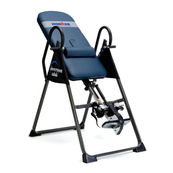
Inversion Table
5402.3‐050516
The specifications of this product may vary from this photo and are subject to change without notice.
IRONMAN, IRONMAN TRIATHLON and M-DOT are registered trademarks of World Triathlon Corporation.
This product is licensed by the World Triathlon Corporation.
Advertisement
Table of Contents

Related Manuals for Ironman Fitness Gravity 4000


Summary of Contents for Ironman Fitness Gravity 4000
- Page 1 OWNER’S MANUAL Inversion Table 5402.3‐050516 The specifications of this product may vary from this photo and are subject to change without notice. IRONMAN, IRONMAN TRIATHLON and M-DOT are registered trademarks of World Triathlon Corporation. This product is licensed by the World Triathlon Corporation.
- Page 2 ...
-
Page 3: Table Of Contents
TABLE OF CONTENTS SERVICE ------------------------------------------------------------------------- 2 LABEL PLACEMENT --------------------------------------------------------- 3 IMPORTANT SAFETY INSTRUCTIONS -------------------------------- 4 OVERVIEW DRAWING ------------------------------------------------------ 6 PARTS LIST -----------------------------------------------------------------------7 HARDWARE & TOOLS PACK---------------------------------------------- 9 ASSEMBLY ---------------------------------------------------------------------- 10 SAFETY OPERATING INSTRUCTIONS --------------------------------- 17 OPERATION & ADJUSTMENTS ------------------------------------------ 18 STORAGE & TROUBLESHOOTING ------------------------------------- 21 WARRANTY -------------------------------------------------------------------- 22 PART REQUEST FORM ---------------------------------------------------- 23... -
Page 4: Service
SERVICE IMPORTANT: FOR NORTH AMERICA ONLY For damaged or defective product, questions, replacement parts or any other service support, please contact our customer service department (8:00 AM - 5:00 PM Pacific Standard Time, Daily) by the below methods: For Best Service, please Email: Service@paradigmhw.com Response Time: 1-2 Business Days Website:... -
Page 5: Label Placement
LABEL PLACEMENT... -
Page 6: Important Safety Instructions
IMPORTANT SAFETY INSTRUCTIONS This inversion table was designed and built for optimal safety. However, certain precautions apply whenever you operate this exercise equipment. Be sure to read the entire manual before assembling and operating this equipment. When using this equipment, basic precautions should always be followed, including the following: ... - Page 7 IMPORTANT SAFETY INSTRUCTIONS WARNING: Risk of personal injury – Keep children away from the machine while in use. WARNING: Risk of personal injury – Do not grab the brake handle for getting up from an inverted position, use the two handle bars instead. WARNING: Risk of personal injury - Keep body parts, hair, loose clothing and jewelry clear of all moving parts.
-
Page 8: Overview Drawing
OVERVIEW DRAWING... -
Page 9: Part List
PART LIST Description Description 001 Front U-Frame 032 Nylon Strap 002 Rear U-Frame 033 Loop Strap 003 Adjustable Boom 034 Strap Lock 004 Bed Frame 035 Foam Bed 005 Pivot Arm 036 Foam Grip 006 Adjustable Lock Plate 037 Protective Cover 007 Steel Heel Holder Bracket 038 Hex Head Bolt M8x23 008 Folding Arm... -
Page 10: Parts List
PART LIST Description Qty No. Description 063 Bolt M6x15 1 069 Shaft Nut Ø8 064 Carriage Bolt M8x70 2 070 Bolt M5x10 065 Bolt M6x30 1 071 Bolt M8x 50 066 Spacer Ø22x16.8 2 072 Pivot Arm Ring 067 Screw ST4.2x12 8 073 Phillips head screw M4x25 068 Screw ST4.8x20 * Most of the components of the following parts list have already been... -
Page 11: Hardware & Tools Pack
HARDWARE & TOOLS PACK... -
Page 12: Assembly
ASSEMBLY Tool: Multi Hex Tool with Phillips Screwdriver Step 1: Stand up the base of the machine by separating the Front and Rear U-Frames (1, 2). Pull the Front and Rear U-Frames (1, 2) apart from each other. Push down on the middle of the Folding Arms (8) until they are fully locked down. - Page 13 ASSEMBLY (55) Nut Cap 2 PCS Step 2: Install a Nut Cap (55) onto the Lock Nuts (15). Slide a Protective Cover (37) on to each side of the base as shown. Pull down on the Protective Covers (37) until the bottom of the covers are slightly lower than the Folding Arms (8). Use the Velcro straps on the bottom of the Protective Covers (37) to secure the covers to the Folding Arms (8).
- Page 14 ASSEMBLY Step 4: Mount the Bed Frame (4) to the Rear U-Frame (2) by inserting the ends of the Pivot Arms (5) into the channels on the plates. The slotted portion of the rollers on the end of the Pivot Arms (5) should be inserted into the channels on the plates.
- Page 15 ASSEMBLY Step 6: Pull out the Large Spring Knob (18) and slide the Adjustable Boom (3) into the square bracket on the bottom of the Bed Frame (4) as shown. Slide the Adjustable Boom (3) to the desired height. Lock the Adjustable Boom (3) in place by releasing the Large Spring Knob (18) and sliding the Adjustable Boom (3) up or down slightly until the Large Spring Knob (18) "pops"...
- Page 16 ASSEMBLY Tool: Multi Hex Tool with Phillips Screwdriver Hex Wrench Step 7: Attach the top end of the Handlebar (29) onto the Rear U-Frame (2) and Pivot Arm Ring (72) with one Hex Head Bolt (38), one Lock Nut (15), and two Washers (13).
-
Page 17: Front U-Frame
ASSEMBLY Step 8: Attach the Nylon Strap (32) to the Strap Lock (34) by inserting the end of the Nylon Strap (32) up through the bottom of the Strap Lock (34), loop the Nylon Strap (32) over the Pre-assembled Loop Strap (33) and down through the Strap Lock (34). - Page 18 ASSEMBLY Step 10: Insert the Velcro strap on the Foam Bed (35) to the Lumbar Pad (47) and secure the Lumbar Pad (47) onto the Foam bed (35).
-
Page 19: Safety Operating Instructions
SAFETY OPERATING INSTRUCTIONS Incorrect Correct The slot of the Pivot arm is NOT aligned Make sure the pivot arm is inserted all correctly. The pivot arm must be inserted the way into the slot. When the Pivot all the way into the curved slot. arm is aligned correctly in the groove of the curved slot the pivot arm will be able to move freely. -
Page 20: Operation & Adjustments
OPERATION & ADJUSTMENTS SHORTEN LENGTHEN THE STRAP A nylon strap has been included to restrict the degree of inversion. This strap can be adjusted to different lengths to allow for a greater or lesser degree of inversion. To lengthen the Nylon Strap (32) feed the top end of Nylon Strap (32) into the strap lock, and pull on the lower end of the strap. -
Page 21: Pivot Arm
OPERATION & ADJUSTMENTS PIVOT ARMS The Pivot Arms (5) can be adjusted to allow for a greater or lesser degree of inversion. To adjust the Pivot Arms (5) simply pull out on them until the post is out of the hole, slide them up or down to the desired holes. The bottom hole provides the least amount of inversion, while the top hole provides the greatest amount. - Page 22 PERATION N & ADJ USTMEN NTS USIN NG THE E INVER RSION T TABLE Start by lying fu ully back o on the bed with your hands at your side, or resting g on your thighs s. See Fig. Keep ing your ha ands close e to your b body, begin...
-
Page 23: Storage & Troubleshooting
RAGE & TROUBL LESHOOT TING your conv venience, t he inversio on table ca an be folde d down to place aga ainst wall, under a a bed, or in n a storage e area. y other se ervicing n ot describ bed in thi s manual should b... -
Page 24: Warranty
WARRANTY MANUFACTURER’S LIMITED WARRANTY Paradigm Health & Wellness warrants to the original purchaser that this product is free from defects in material and workmanship when used for the purpose intended, under the conditions that it has been installed and operated in accordance with Paradigm’s Owner’s Manual. -
Page 25: Part Request Form
PARTS REQUEST FORM Paradigm Health & Wellness, Inc. EMAIL THIS FORM WITH YOUR RECIEPT OF PURCHASE TO Service@paradigmhw.com NAME: _______________________________________________________ ADDRESS: ____________________________________________________ CITY ______________ STATE ______________ ZIP ___________________ TELEPHONE: (Day) _____________________________________________ (Night) ____________________________________________ SERIAL#: _____________________________________________________ MODEL#: _____________________________________________________ PURCHASE DATE: ______________________________________________ PLACE OF PURCHASE: _________________________________________ PART # DESCRIPTION “YOUR ORDER WILL BE PROCESSED WITHIN 3 BUSINESS DAYS”...