Table of Contents
Advertisement
Quick Links
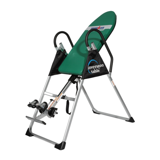
OWNER'S MANUAL
AB TRAINING INVERSION SYSTEM
Model # 5208
Model # 5209
The specifications of this product may vary from this photo and are subject to change without notice.
IRONMAN, IRONMAN TRIATHLON AND M-DOT are registered trademarks of World Triathlon Corporation.
This product is licensed by the IRONMAN TRIATHLON.
Advertisement
Table of Contents

Related Manuals for Ironman Fitness 5208


Summary of Contents for Ironman Fitness 5208
- Page 1 OWNER’S MANUAL AB TRAINING INVERSION SYSTEM Model # 5208 Model # 5209 The specifications of this product may vary from this photo and are subject to change without notice. IRONMAN, IRONMAN TRIATHLON AND M-DOT are registered trademarks of World Triathlon Corporation.
-
Page 2: Table Of Contents
TABLE OF CONTENTS Page # Warning label placement Service Safety precautions Included hardware & tools Overview drawing Part list Assembly Safety operating instructions Operation and adjustments Storage Maintenance instructions Warm-up Warranty Part request fax foam... -
Page 3: Warning Label Placement
WARNING LABEL PLACEMENT... -
Page 4: Service
SERVICE To request for product service and order replacement parts, please call our customer service department at 1-866-924-1688 Monday through Friday, 8:00 am-5:00 pm Pacific Standard Time, service@paradigmhw.com or email at: Please have the following information ready when requesting for service: Owner’s manual Your name Phone number... -
Page 5: Safety Precautions
SAFETY PRECAUTIONS This inversion table was designed and built for optimum safety. However, certain precautions apply whenever you operate the exercise equipment. Be sure to read the entire manual before assembling and operating this equipment. Also, please note the following safety instructions: 1. -
Page 6: Included Hardware & Tools
INCLUDED HARDWARE & TOOLS (11) Hex Head Bolt M6x47 (13) Washer Ø20xØ8.5x1.5 (15) Lock Nut M8 2 PCS 12 PCS 6 PCS (16) Lock Nut M6 (27) Washer Ø16xØ6.5x1.0 (38) Hex Head Bolt M8x23 2 PCS 4 PCS 2 PCS (40) Hex Head Bolt (43) Hex Head Bolt (48) Screw M6x20... -
Page 7: Overview Drawing
OVERVIEW DRAWING... -
Page 8: Part List
PART LIST Part# Part# Description Quan. Description Quan. Front U-Frame Handlebar Rear U-Frame Knob Adjustable Boom Rubber Heel Holder Bed Frame Nylon Strap Pivot Arm Loop Strap Adjustable lnstep Frame Strap Lock Heel Holder Bracket Foam Bed Folding Arm Foam Grip Protective Cover Bolt M8x23 Hex Head Bolt M8x23... -
Page 9: Assembly
ASSEMBLY Stand up the base of the machine by separating the u-frames. Pull the Front and Rear U-Frames (1, 2) as far apart from each others as possible. Then push down on the middle of the two Folding Arms (8) until they are fully locked down. - Page 10 ASSEMBLY Slide the bottom of the Pivot Arms (5) into the brackets, located at each side of the Bed Frame (4), align to the desired hole on the arm with the peg on the bracket. Insert the peg into the hole to lock the pivot arm in place.
- Page 11 ASSEMBLY Attach the top end of Handlebar (29) onto the Rear U-Frame (2) and Pivot Arm Reinforcement Plate (55) with one M8x23 Hex Head Bolt (38), M8 Lock Nut (15), and two Ø20xØ8.5x1.5 Washers (13). Attach the bottom end of the Handlebar (29) onto the Rear U-Frame (2) with one M8x38 Hex Head Bolt (43), M8 Lock Nut (15), and two Ø20xØ8.5x1.5 Washers (13).
- Page 12 ASSEMBLY Attach one Heel Holder Bracket (7) and one Rubber Heel Holder (31) to one end of the Rod (9). Slide the rod through the large round hole on the side of Adjustable Boom (3) as shown, and attach the other Heel Holder Bracket (7) and Rubber Heel Holder (31) to the other end of the Rod (9).
- Page 13 ASSEMBLY Remove the Square End Cap (41) on the back of square bracket of Adjustable Boom (3). Attach the Adjustable Instep Frame (6) to the Adjustable Boom (3) by inserting the Adjustable Instep Frame (6) into the square bracket on the Adjustable Boom (3).
-
Page 14: Front U-Frame 1
ASSEMBLY Attach the Nylon and Loop Straps (32, 33) to the inversion table by hooking the end of the Loop Strap (33) to the pre-assembled loop on the back of the Bed Frame (4) as shown. Now hook the other end of Nylon Strap (32) to the other pre-assembled loop on the Front U-Frame (1) as shown. -
Page 15: Safety Operating Instructions
SAFETY OPERATING INSTRUCTIONS Incorrect Correct Pivot arm is NOT aligned correctly. Make sure the pivot arm is inserted The pivot arm is not inserted all all the way into the slot. Pivot arm is the way into the curved slot. aligned correctly when the groove sits directly on the curved slot and the pivot arm is able to rotate freely. -
Page 16: Operation And Adjustments
OPERATION AND ADJUSTMENTS SHORTEN LENGTHEN THE STRAP For added safety, a nylon strap has been included to restrict the degree of inversion. This strap can be adjusted to different lengths to allow for a greater or lesser degree of inversion. To lengthen the Nylon Strap (32) feed the top end of Nylon Strap (32) into the strap lock, and pull on the lower end of the strap. -
Page 17: Pivot Arm
OPERATION AND ADJUSTMENTS PIVOT ARMS The Pivot Arms (5) can be adjusted to allow for a greater or lesser degree of inversion. To adjust the Pivot Arms (5) simply pull out on them until the post is out of the hole, slide them up or down to the desired hole, push in until the post goes through the desired hole. - Page 18 OPERATION AND ADJUSTMENTS GENERAL PRECAUTIONS 1. Make sure that the Pivot Arms (5) are locks on the lowest hole for the first few attempts. 2. It is recommended that someone be with you while you are using this inversion table for the first few times. 3.
- Page 19 OPERATION AND ADJUSTMENTS BALANCING THE INVERSION TABLE The inversion table is like a very sensitively balanced fulcrum. It responds to very slight changes in weight distribution. So, it is very important to make sure that the height is adjusted properly. To do this, mount the inversion table, lock your ankles into the heel holders, and lie back with your hands at your sides.
- Page 20 OPERATION AND ADJUSTMENTS SUGGESTIONS FOR USE 1. Begin slowly: invert only 15~20 degrees to begin with. Stay inverted only as long as you are comfortable. Return upright slowly. 2. Make gradual changes: increase the angle only if it is comfortable. Increase angle only a few degrees at a time.
-
Page 21: Storage
STORAGE FOLDING THE INVERSION TABLE For your storage convenience, the inversion table can be folded down to place against a wall, under a bed, or in a storage area. To fold the inversion table pull out the Ball Spring Knob (18) and loosen Knob (30). Now, slide the Adjustable Boom (3) all the way up into the frame, until the instep frame is just below the Bed Frame (4), release the Ball Spring Knob (18) and slide the Adjustable Boom (3) slightly up or down until the Ball Spring Knob (18) locks the Adjustable Boom (3) in place. -
Page 22: Maintenance Instructions
MAINTENANCE INSTRUCTIONS You should check your inversion table for any kind of wear and tear before each use. Check the pivot arms, bed, heel holders for wear and tear. Replace damaged and worn components immediately. Keep all damaged equipment out of use until it is repaired. -
Page 23: Warm-Up
WARM-UP The WARM-UP is an important part of any workout. It should begin every session to prepare your body for more strenuous exercise by heating up and stretching your muscles, increasing your circulation and pulse rate, and delivering more oxygen to your muscles. -
Page 24: Warranty
WARRANTY Paradigm Inc. warrants to the original purchaser that this product is free from defects in material and workmanship when used for the purpose intended, under the conditions that it has been installed and operated in according to Paradigm’s Owner’s Manual. -
Page 25: Part Request Fax Foam
PART REQUEST FAX FORM IRONMAN PARTS REQUEST FAX FORM Please fax this form to (1-626-810-2166) OR YOU CAN EMAIL CUSTOMER SERVICE REQUESTS TO service@paradigmhw.com NAME: ___________________________________________________________ ADDRESS: ________________________________________________________ CITY ___________ STATE _______________ ZIP _______________ TELEPHONE: (Day) _________________________________________________ (Night) ________________________________________________ (Email Address) ________________________________________ SERIAL#: _____________________________________________ MODEL#: _____________________________________________ PURCHASE DATE: _________________________________________________...