Table of Contents
Advertisement
Advertisement
Chapters
Table of Contents

Related Manuals for NCE Power Cab


Summary of Contents for NCE Power Cab
- Page 1 Power Cab Power Cab System Reference System Reference Manual Manual Rev. 1.65...
- Page 2 If you own or operate with a PowerHouse or Power NCE system, you can use the Power Cab as a Pro Cab using the 4 wire coiled cord that is also supplied. An NCE P114 power supply (13.8VDC Regulated) is the supplied transformer for your system.
-
Page 3: Quick Start
#1 Assemble the Power Panel by screwing the black plate to the circuit board with screws provided. #2 Connect the long 7 foot flat cable from the Power Cab into the socket marked (with the LED below the jacks) use the left (on the drawing) POWER CAB socket). -
Page 4: Completing The Quick Start
COMPLETING THE QUICK START Operating one locomotive is fun — for awhile. But operating two locomotives is a lot more fun for a much longer time. Advancing beyond this simple DCC testing requires decoder installation into more locomotives and perhaps a few straight pieces added to your circle of track. -
Page 5: Running Two Locomotives With One Cab
By convention all DCC locomotive decoders are set to short address 3 or long address 3333 at the factory. If your decoder has not had its address changed you will see a short address as the active address. Press 1 to set up the address. -
Page 6: Customer Service
ABOUT THIS MANUAL This manual covers the installation and operation of the NCE Power Cab DCC system. It is not a comprehensive tutorial on all the aspects of Digital Command Control. It is not necessary to know the inner workings of DCC to use this system. - Page 7 Power Cab ™ ~ The Finest in Digital Command Control ~ System Reference Manual for Power Cab ™ V 1.65 Copyright 2015 NCE Corporation 82 East Main St. Webster, NY 14580 (585) 265-0230...
-
Page 8: Table Of Contents
PRECAUTIONARY NOTES FOR DECODERS ............9 GENERAL SYSTEM INSTALLATION ..............10 DEVICE LOCATIONS ................... 10 PROGRAMMING TRACK ..................10 NCE AUTO SWITCH .................... 11 REVERSE BLOCKS, WYES, AND CROSSOVERS ........... 11 WIRING ........................11 SYSTEM POWER PANEL DESCRIPTION ............. 12 THE POWER CAB SYSTEM UNIT ............... - Page 9 PROGRAM MACROS ................... 59 BROWSE CONSISTS ................... 61 PROGRAM SIGNAL DECODERS ............... 61 HELPFUL HINTS ....................... 62 TROUBLE SHOOTING .................... 63 COPYRIGHTS ......................64 WARRANTY ....................... 64 FCC STATEMENT ....................65 ABOUT NCE ......................65 MENU NAVIGATION CHARTS ............BACK COVER...
-
Page 10: Installing Decoders
INSTALLING HARD WIRED DECODERS Locomotive decoders come as convenient plug-in models (usually designed for one specific loco or family of locomotives) or as lower cost “hard wired” types that can be wired directly to many different locomotives. Below is a description of a typical hard wired installation. -
Page 11: Precautionary Notes For Decoders
DO NOT USE CONVENTIONAL (older) DECODERS WITH CORELESS MOTORS. NCE decoders that are designated SR (Silent Running) are high frequency motor drive decoders. These will not harm coreless motors. Test the locomotive to assure good analog (DC) operation. Poor running locomotives will not run well with DCC either. -
Page 12: General System Installation
When the switch is set to use the programming track, the remainder of the layout is stopped. With NCE decoders, all parameters can be changed on the mainline using the “Programming on the Main” feature, without shutting down the whole layout. -
Page 13: Nce Auto Switch
You can use the optional NCE Auto SW to automatically turn off your mainline track and let you program one locomotive at a time on your program track. Part number 524-226 is the Auto SW. When the Auto-SW is set to mainline, the program track will be off. -
Page 14: System Power Panel Description
With the flat, 6-wire cable. G Use only the provided P114 power supply or a voltage regulated 10-15 VDC supply of 3 Amps or less. G The flat 6 wire cable carries track power from the Power Cab to the Power Panel . -
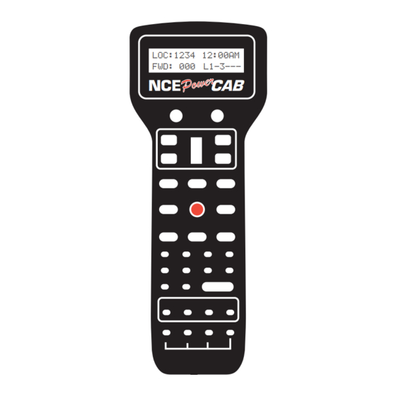
Page 15: The Power Cab
THE POWER CAB DCC COMPATIBLE COMMAND CONTROL LOC:1234 12:00AM FWD: 000 L1-3--- DIRECTION MOMENTUM SPEED INC FAST DEC FAST HORN/ WHISTLE BELL HEADLIGHT EMERGENCY STOP OPTION RECALL SELECT SELECT LOCO MACRO ACCY ENTER CONSIST SET UP CLEAR PROG/ESC EXPN 28/128... -
Page 16: Set The Pro Cab
SET THE PROCAB ADDRESS - If the Power Cab is to be used as a Pro Cab Just as every locomotive has a separate number (address in DCC terms) each cab needs a separate address so the command station can distinguish one cab from another. -
Page 17: Speed Control Section
This rate is adjustable from 0-7. The factory default value is 3. See the Cab Setup section later in this manual. Note: Speed buttons are disabled if the Power Cab is in Yard mode. -
Page 18: Loco And Accessory Selection Group
The number of RECALLS for each cab can be changed within the “SET CAB PARAMS” menu (see PROG button description). The factory default value is two. You may also “clear out” any locomotives in the recall slots using the “SET CAB PARAMS”... -
Page 19: Programming And Extended Function Control
Pressing SHIFT and PROG/ESC activates F10. EXPN/F11 In Power Cab mode, this button is reserved for future features. When the Power Cab is used as a wireless Pro Cab, this button is used to access the radio setup menu. When the cab is tethered, it toggles between the display of lines 1 and 2 of the LCD display and lines 3 and 4. -
Page 20: Cab Setup
LCD. The LCD display will be set to the normal operation display the next time a function is toggled or ENTER is pressed. Pressing SHIFT and 28/128 activates F12. When the Power Cab is turned off, the default is set to 28 speed steps. - Page 21 the “down” direction is continued. Pushing the knob up will reduce the reverse speed to zero then increase it in a forward direction. The factory setting is 2 for “normal” Operation 6) Press ENTER to accept the existing Ballistic Tracking Rate or enter a new rate. Entering a low number will cause the speed knob to change locomotive speed more slowly as the knob is turned.
-
Page 22: Cab Button Numbering Scheme
Power Cab BUTTON NUMBERING SCHEME DCC COMPATIBLE COMMAND CONTROL LOC:1234 12:00AM FWD: 000 L1-3---... -
Page 23: Table Of Factory Default Values
TABLE OF FACTORY DEFAULT VALUES FOR “SHIFTED” KEYS Key # Value ..Description Key # Value ... Description 1 ..67 ..Direction 17 ..96 ..Assign Loco -> Cab 2 ..94 ..Brake 18 ..98 ..Set Clock 3 .. -
Page 24: Wire Cab Bus Cable With Rj-12 Connectors
4 WIRE CAB BUS CABLE WITH RJ-12 CONNECTORS **To prevent potential damage, ALWAYS use 4 wire cables when your Power Cab is used as a Pro Cab. This keeps Power Cab track power from interferring with the NCE cab bus. -
Page 25: Operating Procedures
OPERATING PROCEDURES THE “NORMAL” DISPLAY Current time Loco or consist from system currently being fast clock or LOC:1234 2:00PM controlled display of FWD:108 L1-3--- track current Speed step and direction Status of locomotive of current decoder functions loco TOP ROW OF DISPLAY LOC: Indicates that a locomotive is being operated. -
Page 26: Controlling Headlights And Other Decoder Functions
To select a locomotive for operation: Press the SELECT LOCO button Enter the 1 to 4 digit address of the loco/consist to be operated. A “Leading Zero” is necessary for long addresses below 128. An asterisk will be displayed before any long address below 128 (example below). Press the ENTER key. -
Page 27: Old And Advanced Consists Explained
OLD AND ADVANCED CONSISTS EXPLAINED Before setting up any consist an explanation is needed to understand the operating differences between Advanced and Old Style consists (also called brute force or Universal). Basic decoders that have a short address but no CONSIST address (Early Lenz, MRC 30x/31x series and Digitrax 120 series Decoders) can not be used with advanced consisting. - Page 28 CONSIST ADDRESS: The consist address can be any number from 112 through 127. The system will suggest the first available consist address (the priority is highest to lowest). Press ENTER to accept this address. SETUP SETUP 2:00PM 2:00PM SETUP SETUP SETUP 2:00PM 2:00PM...
-
Page 29: Dropping A Locomotive From An Advanced Consist
Enter the rear loco number followed by the ENTER key. NOTE: If you plan on dropping the rear loco from the consist later on, DO NOT enter it as the rear loco. Enter it later on when prompted for mid-consist locos. ENTERING THE REAR LOCO DIRECTION If the locomotive is to operate in the normal direction press ENTER. -
Page 30: Clearing An Advanced Consist
LOCO LOCO LOCO LOCO LOCO 2:00PM 2:00PM 2:00PM 2:00PM 2:00PM ADD LOCO: ADD LOCO: ADD LOCO: ADD LOCO: ADD LOCO: Enter the loco number to be added and press the ENTER key. Enter the loco’s direction CONSIST CONSIST CONSIST CONSIST CONSIST 2:00PM 2:00PM... -
Page 31: Old Style Consists
OLD STYLE CONSISTS SETUP AN OLD STYLE CONSIST CONSIST CONSIST CONSIST CONSIST CONSIST 2:00PM 2:00PM 2:00PM 2:00PM 2:00PM ENTER=ADV ENTER=ADV ENTER=ADV 1=OLD 1=OLD 1=OLD ENTER=ADV ENTER=ADV 1=OLD 1=OLD Press SETUP. This screen allows you to choose the type of consist to be created. For those consists that will contain any basic decoders, press 1. -
Page 32: Clearing An Old Style Consist
ENTERING THE LOCO DIRECTION TYPE TYPE TYPE 2:00PM 2:00PM 2:00PM TYPE TYPE 2:00PM 2:00PM DIR THIS LOCO: F DIR THIS LOCO: F DIR THIS LOCO: F DIR THIS LOCO: F DIR THIS LOCO: F The locomotive direction is assumed to be forward, if it is to operate in reverse press the DIRECTION key. -
Page 33: Controlling Turnouts And Other Accessories
CONTROLLING TURNOUTS AND OTHER ACCESSORIES ENTER THE ACCESSORY NUMBER TO BE OPERATED CONTROL CONTROL 02:00PM 02:00PM CONTROL CONTROL CONTROL 02:00PM 02:00PM 02:00PM ACC NUMBER: ACC NUMBER: ACC NUMBER: ACC NUMBER: ACC NUMBER: Press the SELECT ACCY key. Enter the address of the accessory to be operated. Followed by pressing the ENTER key. -
Page 34: Momentum Button
THE MOMENTUM BUTTON When you press the momentum button you are prompted to enter a momentum level. There are 9 levels of momentum (1-9) plus ‘direct drive’(0). Pressing a digit button from 0-9 will automatically set the acceleration and deceleration rates of the locomotive(s) being controlled. -
Page 35: Using Macros To Control Turnouts
USING MACROS TO CONTROL TURNOUTS MACROS EXPLAINED Macros are really a list of turnouts controlled by accessory decoders that you wish to operate as a group. There are a total of 16 macros, each one capable of controlling up to 8 turnouts. Macros may be ‘chained’ with other macros to create complex routes with hundreds of turnouts. -
Page 36: Programming Procedures
PROGRAMMING PROCEDURES ACCESSING PROGRAMMING MODES To access the various programming modes, press the PROG/ESC key. The following messages will be displayed for each press of the PROG/ESC key. When the desired mode is displayed, press the ENTER key to enter that mode. To quickly get to a programming mode, press the PROG/ESC key and then press the number of the screen. -
Page 37: Programming Menus Table Of Contents
SET DECODER CONFIGURATION (OPTION 3) ..........38 SET MOTOR CONTROL PARAMETERS (OPTION 4) ........39 SET UP DECODER OUTPUT/FUNCTION MAPPING (OPTION 5) ....41 SET UP NCE LIGHTING EFFECTS (OPTION 6) ..........42 QSI PROGRAMMING (OPTION 8) ..............43 BINARY CV PROGRAMMING (OPTION 9) ............43 ASSIGNING A LOCO TO A CAB ................ - Page 38 NUMBER OF STOP PACKETS ................55 NUMBER OF TEMP PACKETS ................55 NUMBER OF ACCESSORY PACKETS .............. 56 NUMBER OF HORN OFF PACKETS ..............56 NUMBER OF PROGRAM PACKETS ..............56 SEND FUNCTION COMMANDS TO CONSIST ADDRESS ......56 CONSIST MOMENTUM ..................56 MOMENTUM MULTIPLIER ..................
-
Page 39: Programming On The Main
2 ......CHANGE ANY CV IN THE DECODER 3 ......SET UP THE DECODER CONFIGURATION (CV29) 4 ......MOTOR CONTROL 5 ......FUNCTION MAP 6 ......NCE EFFECTS 7 ......Not Used 8 ......QSI SOUND 9 ......BIN ADDRESS PROGRAMMING (Option 1) This option provides a means by which to program the address of your locomotive. -
Page 40: Cv Programming (Option 2)
Enter the new address for the locomotive. The new address will be sent to the locomotive and you will be returned to the normal display with the locomotive selected and ready to run. Most decoders allow programming the address while on the mainline. -
Page 41: Set Motor Control Parameters (Option 4)
DC (Analog) MODE Press ENTER to turn DC operation mode off, press 1 to turn DC mode on. We recommend leaving DC mode off for most layouts. This is to prevent all your locomotives from taking off at once in case of a failure in your power station or someone accidentally connecting the track to a DC power supply (it happens more often than you might think). - Page 42 MAXIMUM VOLTAGE (CV5) This is the amount of voltage applied to the motor at full speed. A value of 255 means send the full available track voltage to the motor. Lower numbers will tell the decoder to send proportionally less voltage when full speed is called for. PROG PROG 11:22AM...
-
Page 43: Set Up Decoder Output/Function Mapping (Option 5)
NCE TORQUE COMPENSATION (Dither) KICK RATE (CV116) Newer NCE decoders (V3.5+) provide Torque Compensation for smooth low speed operation. Torque Compensation gives a steady stream of ‘kicks’ to the motor when running at very low speeds. You can adjust how often the motor is kicked (Kick Rate) and how hard it is kicked (Kick Strength). -
Page 44: Setup Nce Lighting Effects (Option 6)
10, 1 for output 11, etc. Pressing PROG/ESC will exit from mapping at any time. SETUP NCE LIGHTING EFFECTS (Option 6) You can use this option to customize the lighting effects for your NCE decoder equipped locomotives. This programming option will only work with NCE decoders. 07:04... -
Page 45: Qsi Programming (Option 8)
REGULAR BULB REGULAR BULB REGULAR BULB REGULAR BULB REGULAR BULB 1=BULB 1=BULB 1=BULB 1=BULB 1=BULB 2=LED 2=LED 2=LED 2=LED 2=LED Last, press 1 if the output has a regular incandescent bulb attached. Press 2 if the output has an LED connected. LEDs behave differently when dimmed than incandescent bulbs. Pressing 1 or 2 informs the decoder which set of lighting characteristics to use for this output. -
Page 46: Assigning A Loco To A Cab
ASSIGNING A LOCO TO A CAB (shortcut = PROG 2 ) This selection passes a loco or consist from one cab to another. This is especially useful when the other operator is a novice or has a Basic Cab. The locomotive/ consist is passed to the assigned cab and the locomotive/consist controlled by the other cab is passed back to the original cab. -
Page 47: Entering The Minute
TIME TIME TIME TIME TIME 02:00PM 02:00PM 02:00PM 02:00PM 02:00PM ENTER HOURS: ENTER HOURS: ENTER HOURS: ENTER HOURS: ENTER HOURS: ENTERING THE MINUTE Enter the starting minute. Use 0 through 59. Press ENTER. TIME TIME TIME TIME TIME 02:00PM 02:00PM 02:00PM 02:00PM 02:00PM... -
Page 48: Use Program Track
8 = DECODER UNLOCK Unlocks a “Lockable, NCE decoder. The first three options are displayed below. Press ENTER to see more options. For example: If you wish to program the “Standard” locomotive parameters, press 1, if you want to program decoder CVs press 2. -
Page 49: Standard Programming (Option 1)
NMRA standard function mapping and finally any additional CVs you may wish to program. DECODER MANUFACTURER This is the NMRA assigned manufacturer number of the decoder. All NCE decoders respond with 11. Press ENTER to continue. MAIN... -
Page 50: Display Of Active Address
DISPLAY OF ACTIVE ADDRESS The current active address (long or short) is indicated on the top line of the display. If you wish to change the decoder address press 1. Any other button will skip programming the address and continue standard programming. ACTIVE ACTIVE ADR:SHORT... -
Page 51: Direction Bit
SET CFG? SET CFG? SET CFG? SET CFG? SET CFG? ENTER=NO ENTER=NO ENTER=NO ENTER=NO ENTER=NO 1=YES 1=YES 1=YES 1=YES 1=YES You will be asked a series of questions regarding the basic operation of the locomotive. If you are in doubt about the proper answer just press ENTER and you will usually be OK. -
Page 52: Setting Up Motor Control Parameters
ADDRESS ADDRESS ADDRESS ADDRESS ADDRESS 02:00PM 02:00PM 02:00PM 02:00PM 02:00PM ENTER=S ENTER=S ENTER=S ENTER=S ENTER=S 1=LONG:_ 1=LONG:_ 1=LONG:_ 1=LONG:_ 1=LONG:_ SETTING UP MOTOR CONTROL PARAMETERS This option can be used to setup the various locomotive motor speed control parameters. You can skip adjusting any of these parameters (CVs) by pressing ENTER. -
Page 53: Deceleration
NCE TORQUE COMPENSATION (Dither) KICK RATE (CV116) If your decoder supports NCE torque compensation this menu item will be displayed. If not you will be sent to SET UP FUNCTION MAPPING. NCE decoders since version 3.5 provide Torque Compensation for smooth low speed operation. -
Page 54: Set Up Decoder Function Mapping
Function outputs mapped to these CVs will be directional unless the same output is mapped to both CVs. CVs 33 and 34 are both for the F0 function. On NCE decoders CV33 and CV34 do not provide directionality (see SETUP NCE LIGHTING EFFECTS on page 53) but otherwise operate the same as above. -
Page 55: Set Any Cv (Option 2)
press the digit key that is 10 less than the output number. Example: press 0 for output 10, 1 for output 11, etc. Pressing PROG/ESC will exit from mapping at any time. SET ANY CV (Option 2) This option allows you to change any configuration variable (range of 1-999) in your decoder. -
Page 56: Paged Programming (Option 4)
Older decoders (built prior to 1/1/2001) do not support Direct Mode programming. SETUP NCE LIGHTING EFFECTS (Option 6) You can use this option to customize the lighting effects for your NCE decoder equipped locomotives. This programming option will only work with NCE decoders. 07:04AM... -
Page 57: Setup Command Station
CV15=XX SETUP COMMAND STATION (Shortcut = PROG 5) This allows the operator to view the Power Cab’s version number and set various system (not decoder) parameters. DISPLAY SOFTWARE VERSION AND DATE This screen is important when the time comes to call or write about a question or a problem. -
Page 58: Number Of Accessory Packets
NUMBER OF ACCESSORY PACKETS (default is 4) This adjusts the number of accessory control commands sent when an accessory or signal is controlled. Factory default is 4. Press ENTER to skip setting this parameter. NUMBER NUMBER 02:00PM 02:00PM NUMBER NUMBER NUMBER 02:00PM 02:00PM... -
Page 59: Setting The Cab Parameters
ENABLE 1=Y 0=N 1=Y 0=N RESET SYSTEM? Reset System will reset all of the system configuration settings to their factory defaults. Only the Power Cab memory will be reset, the memory as a Pro Cab will remain. RESET RESET RESET... -
Page 60: Number Of Recalls
NUMBER OF RECALLS This adjusts the number of recall “slots” that are cycled through when the RECALL key is pressed. Enter a number of Recalls from 1 - 6 and press ENTER. This can be set differently for each Cab. (factory default is 2) Press ENTER to skip setting this parameter. -
Page 61: Program Accessory Decoders On The Main
PROGRAM ACCESSORY DECODERS (Shortcut = PROG 7) This allows the operator to set Accessory Decoder CVs while they are connected to the Track (Accessory Programming on the Main). ENTER THE ACCESSORY ADDRESS Enter the Accessory Decoder address and press ENTER. PROG PROG PROG... -
Page 62: Linking Macros
ENTER THE ACCESSORY ADDRESS LINKING MACROS Enter the Accessory Address that you want to control, and press ENTER. A macro can be linked to another macro by entering an accessory address of 9999 at this point. You will be prompted for the macro number to link. MAC: MAC: MAC:... -
Page 63: Browse Consists
BROWSE CONSISTS (Shortcut = PROG 9) This option lets you see what advanced consists are currently in the memory of the system. Press ENTER at the “BROWSE CONSISTS” prompt. The LCD will display the highest numbered consist in the system memory. It will look something like: CON: CON: 10:42AM... -
Page 64: Helpful Hints
“flipped” over at opposite ends of the wire. See the illustration on page 21 for proper cab bus cabling. Using the Power Cab/ProCab In DCC there are 2 kinds of addresses (loco numbers), long and short. When entering the address of the loco you wish to control long addresses from 1 to 127 are entered by preceding the actual number by a zero. -
Page 65: Trouble Shooting
TROUBLE SHOOTING Locomotive was running yesterday but today it just sits there - The headlight and other functions are controllable but it won’t run. - This sometimes happens when you clear a consist but for some reason the decoder misses the command. Use the DEL LOCO button to “re-delete”... -
Page 66: Copyrights
To protect the warranty, please contact the Warranty Center for authorization prior to altering any product. In no event will NCE’s liability exceed the price paid for the product from direct, indirect, special, incidental or consequential damages resulting from the use of the product, it’s accompanying software or its documentation. -
Page 67: Fcc Statement
This has helped NCE to grow into a full time electronic design and manufacturing firm devoted entirely to the development and sale of products for the control of model railroads. -
Page 68: Menu Navigation Charts
Enter Value Momentum button Multiplier Momentum Decel Rate Manufacturer Function Refresh Decoder Enable Version Reset System? Set Up Address Set Config 6 NCE 7 Recovery 8 Decoder Motor Control Effects Program Unlock Function Map Factory Output # Reprogram? Set CV Choose... - Page 69 NAVIGATION CHART - Part 2 e through menu listings, then press ENTER to cycle through listing choices SET CMD SET CAB PROG ACCY PROGRAM BROWSE PROG SIG STATION PARAMS ON MAIN MACROS CONSISTS ON MAIN Version Track Current Accy Address Enter Signal # # of Stop Recalls...
- Page 70 DC Mode? Mid Volts Outputs Run Loco Adv Acknowledge? Accel SpeedTable Decel Address PWM Freq Kick Rate Kick Depth 6 NCE 7 Not Used 8 QSI 9 BIN CV Effects Sound Factory Output # Enter CV # Reprogram? Choose Enter Value...
- Page 71 NCE Corporation 82 East Main St. Webster, NY 14580 (585) 265-0230 ncedcc.com 05240301 05240301 05240301 05240301 05240301 05240301...