Advertisement
Table of Contents
- 1 Basic Set up of 5 Amp
- 2 Power Pro System
- 3 Quick Start
- 4 Trying out Your Power Pro
- 5 Completing the Quick Start
- 6 Programming a Locomotive Address
- 7 Running Two Locomotives with One Cab
- 8 To Select the Locomotive
- 9 Advanced Layout Wiring
- 10 Menu Navigation Chart
- 11 Menu Navigation Chart
- Download this manual
Advertisement
Table of Contents

Related Manuals for NCE Power Pro


Summary of Contents for NCE Power Pro
- Page 1 Power Pro Power Pro System Reference System Reference Manual Manual Version 3.1.07...
- Page 2 18 Volts do not use it. The maximum input voltage to your Power Pro or PB105 is 18 Volts AC. Voltages higher than 18 Volts AC will ultimately destroy your booster resulting in an expensive repair charge.
- Page 3 Power Pro to the “Power Booster” portion. #4 If in place, pull the 4 pin plug from its socket on the face of the Power Pro. Connect your power source to the screw terminals marked POWER. Your power source must have a voltage output within the range of 12-18 volts AC or 18-28 volts DC.
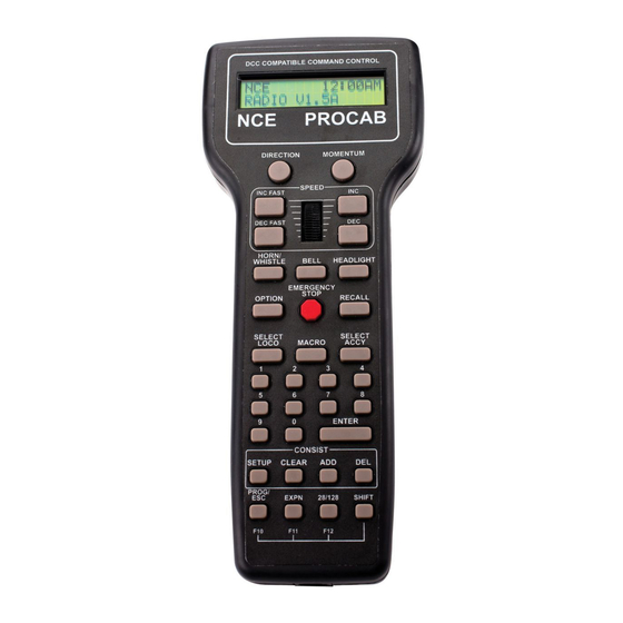
- Page 4 The following cab buttons must be pressed in the proper sequence to acquire control of the locomotive #3 (in the above example locomotive #3 is already selected): a. Press SELECT LOCO button once. b. Press the “3” button once. DO NOT press 0 then 3. c.
- Page 5 NOTE: The STATUS light of the booster will flash rapidly indicating that the power booster portion of the system has turned off track power. This is due to a loss of DCC signal from the command station half of the Power Pro and is normal when using the programming track.
- Page 6 Press 1 to set up the address. ACTIVE ACTIVE ADR:SHORT ADR:SHORT ACTIVE ACTIVE ACTIVE ADR:SHORT ADR:SHORT ADR:SHORT SETUP ADR SETUP ADR 1=YES 1=YES SETUP ADR SETUP ADR SETUP ADR 1=YES 1=YES 1=YES By convention all DCC locomotive decoders are set to short address #3 at the factory. If your decoder has not had its address changed you will see a short address as the active address.
- Page 7 Town Foundry Cab05 R POWER PRO POWER PRO PB105 PB105 Ground Wire P515 P515 RPT1 RPT1 TIP: Rick Lake of St. Louis passes along this simple but quite innovative suggestion that his wife, Venita came up with. When wiring a railroad, use an old or not too special box car and paint one side red and the other side blue.
- Page 8 Processor Mine DPDT Switch ProCab R PH Pro POWER PRO ProCab Cab04E Cab04P PROCAB P515 RB02 Advanced Layout Wiring...
- Page 9 DC Mode? Mid Volts Outputs Run Loco Adv Acknowledge? Accel SpeedTable Decel Address PWM Freq Kick Rate Kick Depth 6 NCE 8 QSI 9 BIN CV 0 Broadcast Effects Sound Factory Output # Enter CV # Reprogram? Choose Enter Value...
- Page 10 Prog Signals Set Up Address Radio Fix Highest cab # Highest Cab # to Prog on Main Set Config to Prog Consists AIU Broadcast 6 NCE 7 Recovery Motor Control Enable Highest Cab # Clear All Effects Program to Assign Loco...
- Page 11 NCE Corporation 82 East Main Street Webster, NY 14580 (585) 265-0230 ncedcc.com 05240300 05240300 05240300 05240300 05240300 05240300...