Advertisement
Quick Links
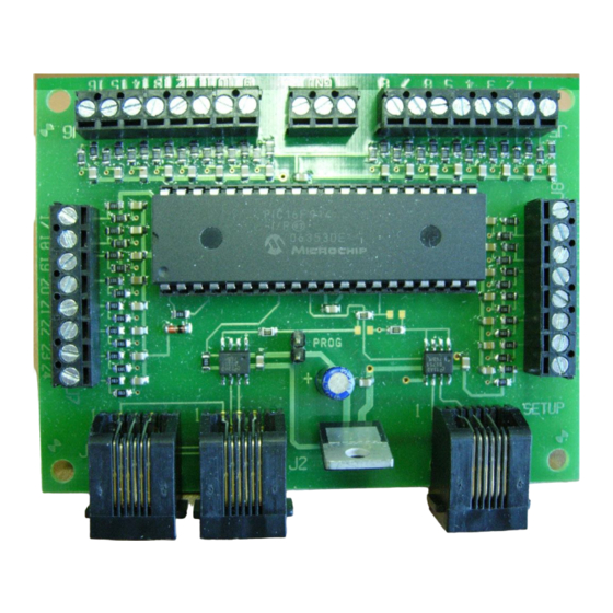
Dimensions: 3.20" x 2.70" (81 x 69 mm)
Build the kind of control panels you've always
wanted without complicated wiring!
Use one button to control multiple switches or macros on your NCE DCC
Up to 30 pushbuttons, toggle switches, block detectors, etc. can be
connected for control of turnouts, signals and other devices
Easy programming, just plug in a ProCab
Simple hook up, one Cab Bus connection and 2 wires for each
pushbutton or other input device
Can be used to perform simple automatic train control and other
layout automation tasks
This book, schematics and artwork copyright 2008
NCE Corporation 82 East Main Street Webster, NY 14580
Last revised: 9 December 2008
Mini Panel
Accy and Macro Controller
Revision 1.00
$49.95
05240230
05240230
Advertisement

Related Manuals for NCE Mini Panel


Summary of Contents for NCE Mini Panel
- Page 1 Build the kind of control panels you’ve always wanted without complicated wiring! Use one button to control multiple switches or macros on your NCE DCC Up to 30 pushbuttons, toggle switches, block detectors, etc. can be connected for control of turnouts, signals and other devices ...
-
Page 2: Installation Notes
CV read and write commands (page or direct mode). USB jumpers should be set for PowerCab v1.28. CV7 and CV8 return the manufacturer number and version of the Mini Panel as with a decoder when used with the USB interface. See the Mini Panel Technical Reference for additional USB information. - Page 3 Wiring: See the diagram below for sample wiring ideas. Cab Bus Plug in ProCab can be or USB interface daisy chained for setup through the Mini-Panel Optional Reset Push button SETUP CAB BUS PIN 1 Push Button Toggle 9 10 11 12 13 14 15 16 1 2 3 4 5 6 7 GROUND Switch...
- Page 4 'daisy chain' the Cab Bus through the mini panel. Once the wiring is complete it is time to setup the Mini Panel to send the commands for correct alignment of the yard switches when each button is pushed.
- Page 5 Normally when setting up an input we start with step number 1. We want to start programming at step 1 so just press ENTER to accept that step. Commands will be sent from the Mini Panel in order of their step number until an ‘empty’ step is encountered or four steps are completed.
- Page 6 1 will be sent. 1=SETUP 2=REVIEW 3=TEST OPERATION Putting the Mini Panel into test mode will also allow testing of any input by grounding that input number. Pressing any button on the ProCab will return the Mini Panel to setup mode.
- Page 7 Press “ENTER” again to see the “OTHER CMDS” Prompt. INP: 01 STEP: 2 5=OTHER CMDS Press ”5” to be presented with “OTHER” commands that are available SELECT CMD GROUP 1=DELAYS 2=WAIT Press “ENTER” to see even more options SELECT CMD GROUP 3=LINK 4=CV PROG Press “3”...
- Page 8 After a 1 second delay the second accessory command will be sent. NOTE: The Mini Panel will do nothing while it is performing a delay. If you use a very long delay activity on other inputs may be missed. With the short delays...
- Page 9 Last revised: 9 December 2008 Page 9...
-
Page 10: Command Descriptions
Accessory/Macro commands covered in this manual Accessory Command - all NMRA standard accessory addresses (1-2044) can be sent via the accessory command Macro command - all NCE macro numbers (0-255) can be sent via the Macro command Link Command ... - Page 11 The terms Silent Running, Power Pro, PowerCab , ProCab, Switch-It the NCE logo with “Power of DCC” slogan are trademarks of NCE Corporation. The distinctive shape of the ProCab when used with a thumb wheel speed control and LCD display is a trademark of NCE Corporation.