Table of Contents
Advertisement
Quick Links
R-410A
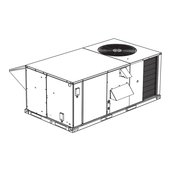
DM SERIES
3 - 6.3 Ton
50 Hertz
General . . . . . . . . . . . . . . . . . . . . . . . . . . . . . . . . . . . . . . . . . . 3
Installation . . . . . . . . . . . . . . . . . . . . . . . . . . . . . . . . . . . . . . . . 7
Installation Safety Information. . . . . . . . . . . . . . . . . . . . . . . 7
Limitations . . . . . . . . . . . . . . . . . . . . . . . . . . . . . . . . . . . . . . 7
Location. . . . . . . . . . . . . . . . . . . . . . . . . . . . . . . . . . . . . . . . 8
Rigging And Handling . . . . . . . . . . . . . . . . . . . . . . . . . . . . . 8
Condensate Drain . . . . . . . . . . . . . . . . . . . . . . . . . . . . . . . . 9
Compressors. . . . . . . . . . . . . . . . . . . . . . . . . . . . . . . . . . . . 9
Filters . . . . . . . . . . . . . . . . . . . . . . . . . . . . . . . . . . . . . . . . . 9
Service Access . . . . . . . . . . . . . . . . . . . . . . . . . . . . . . . . . . 9
DM036-072) . . . . . . . . . . . . . . . . . . . . . . . . . . . . . . . . . . . 12
Thermostat . . . . . . . . . . . . . . . . . . . . . . . . . . . . . . . . . . . . 12
Power And Control Wiring. . . . . . . . . . . . . . . . . . . . . . . . . 12
Optional Electric Heat . . . . . . . . . . . . . . . . . . . . . . . . . . . . 13
Optional Gas Heat. . . . . . . . . . . . . . . . . . . . . . . . . . . . . . . 14
Gas Piping. . . . . . . . . . . . . . . . . . . . . . . . . . . . . . . . . . . . . 14
Gas Connection . . . . . . . . . . . . . . . . . . . . . . . . . . . . . . . . 15
L.p. Units, Tanks And Piping. . . . . . . . . . . . . . . . . . . . . . . 15
Vent And Combustion Air Hoods . . . . . . . . . . . . . . . . . . . 16
Jade Economizer Interface Overview . . . . . . . . . . . . . . . . 17
Simplicity SE Economizer Sequences . . . . . . . . . . . . . . . 19
Dry Bulb Changeover . . . . . . . . . . . . . . . . . . . . . . . . . . . . 19
Single Enthalpy Changeover. . . . . . . . . . . . . . . . . . . . . . . 19
Dual Enthalpy Changeover . . . . . . . . . . . . . . . . . . . . . . . . 19
Auto. . . . . . . . . . . . . . . . . . . . . . . . . . . . . . . . . . . . . . . . . . 19
Free Cooling Operation. . . . . . . . . . . . . . . . . . . . . . . . . . . 19
Power Exhaust . . . . . . . . . . . . . . . . . . . . . . . . . . . . . . . . . 20
Operation . . . . . . . . . . . . . . . . . . . . . . . . . . . . . . . . . . . . . 20
DM036-076 Unit Weights . . . . . . . . . . . . . . . . . . . . . . . . . 25
Phasing . . . . . . . . . . . . . . . . . . . . . . . . . . . . . . . . . . . . . . . 34
Supply Air Blowers . . . . . . . . . . . . . . . . . . . . . . . . . . . . . . 35
Checking Supply Airflow Rate. . . . . . . . . . . . . . . . . . . . . . 35
Operation . . . . . . . . . . . . . . . . . . . . . . . . . . . . . . . . . . . . . . . 36
Cooling Sequence Of Operation . . . . . . . . . . . . . . . . . . . . 36
Electric Heating Sequence Of Operations . . . . . . . . . . . . 38
TABLE OF CONTENTS
Safety Controls . . . . . . . . . . . . . . . . . . . . . . . . . . . . . . . . . 38
Heat Anticipator Setpoints. . . . . . . . . . . . . . . . . . . . . . . . . 39
Gas Heating Sequence Of Operation . . . . . . . . . . . . . . . . 39
Gas Heat Operation Errors . . . . . . . . . . . . . . . . . . . . . . . . 39
Flash Codes Or Error Messages. . . . . . . . . . . . . . . . . . . . 40
Heat Anticipator Setpoints. . . . . . . . . . . . . . . . . . . . . . . . . 40
Start-up (Cooling) . . . . . . . . . . . . . . . . . . . . . . . . . . . . . . . . . 41
Prestart Check List . . . . . . . . . . . . . . . . . . . . . . . . . . . . . . 41
Operating Instructions . . . . . . . . . . . . . . . . . . . . . . . . . . . . 41
Post Start Check List. . . . . . . . . . . . . . . . . . . . . . . . . . . . . 41
Shut Down. . . . . . . . . . . . . . . . . . . . . . . . . . . . . . . . . . . . . 41
Start-up (Gas Heat) . . . . . . . . . . . . . . . . . . . . . . . . . . . . . . . . 41
Pre-start Check List. . . . . . . . . . . . . . . . . . . . . . . . . . . . . . 41
Operating Instructions . . . . . . . . . . . . . . . . . . . . . . . . . . . . 41
Post-start Check List (Gas) . . . . . . . . . . . . . . . . . . . . . . . . 41
Manifold Gas Pressure Adjustment. . . . . . . . . . . . . . . . . . 42
Pilot Checkout . . . . . . . . . . . . . . . . . . . . . . . . . . . . . . . . . . 42
Burner Instructions . . . . . . . . . . . . . . . . . . . . . . . . . . . . . . 42
Burner Air Shutter Adjustment . . . . . . . . . . . . . . . . . . . . . 42
Checking Gas Input. . . . . . . . . . . . . . . . . . . . . . . . . . . . . . 42
Adjustment Of Temperature Rise . . . . . . . . . . . . . . . . . . . 43
Troubleshooting . . . . . . . . . . . . . . . . . . . . . . . . . . . . . . . . . . 44
Cooling Troubleshooting Guide. . . . . . . . . . . . . . . . . . . . . 44
Gas Heat Troubleshooting Guide . . . . . . . . . . . . . . . . . . . 45
Flash Code Troubleshooting . . . . . . . . . . . . . . . . . . . . . . . 46
Symptomatic Troubleshooting. . . . . . . . . . . . . . . . . . . . . . 48
Unit Flash Codes. . . . . . . . . . . . . . . . . . . . . . . . . . . . . . . . 49
Fan On And Off Delays . . . . . . . . . . . . . . . . . . . . . . . . . . . 49
Simplicity SE Control Board Navigation Components . . . . . . 50
Basic Unit Control Board Navigation Examples: . . . . . . . . 51
Typical Wiring Diagrams . . . . . . . . . . . . . . . . . . . . . . . . . . . . 59
Simplicity® Lite Control Board . . . . . . . . . . . . . . . . . . . . . 59
Simplicity® Smart Equipment (SSE) . . . . . . . . . . . . . . . . . 63
Start-Up Sheet . . . . . . . . . . . . . . . . . . . . . . . . . . . . . . . . . . . 67
A
Advertisement
Table of Contents
Troubleshooting

Related Manuals for York DM036


Summary of Contents for York DM036
-
Page 1: Table Of Contents
Shut Down........41 DM036-072) ........12 Start-up (Gas Heat) . - Page 2 24 Electric Heat Anticipator Setpoints ....39 11 DM036-076 Physical Data ..... . . 26 25 Limit Control Setting .
-
Page 3: General
5011492-XIM-B-0815 General YORK Model DM units are either single package air conditioners equipped with optional factory installed electric heaters, or single package gas-fired central heating furnaces with cooling unit. Both are designed for outdoor installation on a FIRE OR EXPLOSION HAZARD rooftop or slab. - Page 4 5011492-XIM-B-0815 Due to system pressure, moving parts, and electrical components, installation and servicing of air conditioning equipment can be hazardous. Only qualified, trained service personnel should install, repair, or service this equipment. Before performing service or maintenance operations on Untrained personnel can perform basic maintenance functions unit, turn off main power switch to unit.
- Page 5 5011492-XIM-B-0815 Renewal Parts ® Contact your local York parts distribution center for authorized replacement parts. Improper installation may create a condition where the operation of the product could cause personal injury or Approvals property damage. Design for use as follows: For use as a cooling only unit, cooling unit with supplemental electric heat or a forced air furnace.
- Page 6 5011492-XIM-B-0815 Product Nomenclature D M 048 N04 A 7 A AA 4 0 1 2 4 A Product Category Product Style D = A/C, Single Pkg., R22 A = Style A Product Identifier Configuration Options (not required for all units) These four digits will not be assigned until a quote is requested, or an order placed.
-
Page 7: Installation
5011492-XIM-B-0815 Installation Limitations These units must be installed in accordance with the following: Installation Safety Information In U.S.A.: Read these instructions before continuing this appliance National Electrical Code, ANSI/NFPA No. 70 - Latest installation. This is an outdoor combination heating and cooling Edition unit. -
Page 8: Location
If a unit is to be installed on a roof curb or special frame other surfaces that come in contact with the unit underside. than a YORK roof curb, gasketing must be applied to all surfaces that come in contact with the unit underside. -
Page 9: Condensate Drain
5011492-XIM-B-0815 Clearances Compressors All units require particular clearances for proper operation and Units are shipped with compressor mountings factory-adjusted service. Installer must make provisions for adequate and ready for operation. combustion and ventilation air in accordance with section 5.3 of Air for Combustion and Ventilation of the National Fuel Gas Units with scroll compressors have a shipping bracket which Code, ANSI Z223.1 –... - Page 10 5011492-XIM-B-0815 Refer to the Dimensions and Clearances shown in Figures 12, 13, 14 and 15 for location of these access panels. Make sure that all screws and panel latches are replaced and properly positioned on the unit to maintain an airtight seal. Johnson Controls Unitary Products...
- Page 11 R, RC, or RH. OCC is an output from the thermostat to indicate the Occupied X is an input to the thermostat to display Error Status condi ons. Figure 3: Typical Field Power & Simplicity Lite DM036-076 Control Wiring Johnson Controls Unitary Products...
-
Page 12: Typical Cool/Heat Control Wiring (Simplicity Se Dm036-072)
5011492-XIM-B-0815 Typical Cool/Heat Control Wiring (Simplicity SE DM036-072) CONTROL TERMINAL THERMOSTAT BLOCK TERMINALS SD-24 Smoke Detector 24 VAC Class 2 SD-24 Jumper Located on Harness (If Smoke Detector Is Used) TERMINALS ON A (If No Smoke Detector) LIMITED NUMBER OF THERMOSTATS... -
Page 13: Optional Electric Heat
5011492-XIM-B-0815 conditions, are indicated on the unit Rating Plate and the Unit Refer to the Typical Field Wiring Figures 3 and 4 and to the Application Data table. appropriate unit wiring diagram for control circuit and power wiring information. Table 2: Control Wire Sizes 380/415-3-50 units control transformers are factory Wire Size Maximum Length... -
Page 14: Optional Gas Heat
5011492-XIM-B-0815 Table 3: Electric Heater Supply Air Limitations HEATER SIZE NOMINAL KW UNIT MODEL SIZE MINIMUM SUP- VOLTAGE NOMINAL TONS PLY AIR 0.47 0.57 0.57 0.61 380/415-3-50 1100 1200 1200 1300 0.61 0.61 0.61 0.61 380/415-3-50 1300 1300 1300 1300 0.75 0.75 0.75... -
Page 15: Gas Connection
5011492-XIM-B-0815 Gas Connection The gas supply line can be routed through the knockouts located on the front of the unit or through the opening provided in the unit's base. Refer to Figure 13 to locate these access FIRE OR EXPLOSION HAZARD openings. -
Page 16: Vent And Combustion Air Hoods
5011492-XIM-B-0815 Vent And Combustion Air Hoods The vent hood and combustion air hood (with screens) are shipped attached to the blower housing in the blower compartment. These hoods must be installed to assure proper unit function. All hoods must be fastened to the outside of the gas heat access panel with the screws provided in the bag also attached to the blower housing. -
Page 17: Jade Economizer Interface Overview
5011492-XIM-B-0815 Optional Economizer And Power Exhaust Damper Set Point Adjustments And Information Remove the economizer access panel from the unit. Loosen but do not remove the two panel latches. Locate the economizer control module, where the following adjustments 2 LINE will be made. -
Page 18: Single Enthalpy And Dual Enthalpy High Limit Curves
5011492-XIM-B-0815 • CHANGE STORED displays. Economizer Setup And Configuration • Press the button (MenuUp/Exit) to return to the Before being placed into service, the JADE™ Economizer previous menu. module must be setup and configured for the installed system. Menu Structure NOTE: During setup, the Economizer module is live at all times. -
Page 19: Simplicity Se Economizer Sequences
5011492-XIM-B-0815 When conditions are above the selected boundary, the Dual Enthalpy Changeover conditions are not good to economize and the mode is set to For dual enthalpy economizer operation, the outside air enthalpy must be lower than the return air enthalpy by 1 btu/lb Fig. -
Page 20: Power Exhaust
5011492-XIM-B-0815 At no time will a compressor output be turned ON if the d. Exhaust VFD Installed economizer output is less than 100%, even if the differential e. Building Pressure Sensor Enabled between zone (or return) temperature and the current cooling f. -
Page 21: Simplicity Se Economizer Board Details
5011492-XIM-B-0815 Figure 10: SE-ECO1001-0 Economizer Controller Table 7: Simplicity SE Economizer Board Details Cover Label Description Function & Comments Directional orientation: viewed with the center text of the cover label upright ANALOG INPUTS Terminal at left on upper edge of economizer board 24 VAC common/0-10 VDC negative for Connects through circuit trace to 24V~ IN pin COM economizer actuator position feedback... - Page 22 5011492-XIM-B-0815 Table 7: Simplicity SE Economizer Board Details (Continued) Cover Label Description Function & Comments SA BUS Pin connections at left on upper edge of economizer board EconCtrlr parameter reports UCB-to-economizer board SA bus communication status. Negative of the SA BUS communication Common for SA BUS power and circuit to the UCB.
- Page 23 5011492-XIM-B-0815 Table 7: Simplicity SE Economizer Board Details (Continued) Cover Label Description Function & Comments 24V~ IN Pin connections at right on upper edge of economizer board 24 VAC common connection to power the economizer board. 24 VAC transformer Common referenced to Connects through circuit traces to C/COM terminals and pins cabinet ground distributed on the economizer board.
- Page 24 5011492-XIM-B-0815 Table 7: Simplicity SE Economizer Board Details (Continued) Cover Label Description Function & Comments 24 VAC hot supplied for the building pressure 24V~ Connects through circuit trace to 24V~ IN pin HOT sensor BldgPres parameter reports input status (-.250-.250”/w/-.062- BLDG 0-5 VDC positive input from the Building .062kPa).
-
Page 25: Dm036-076 Unit Weights
5011492-XIM-B-0815 DM036-076 Unit Weights Figure 11: Four And Six Point Loading 1140 BACK OF UNIT mm[inch] BACK OF UNIT mm[inch] 1140 2089 2089 APPROXIMATE APPROXIMATE CENTER OF GRAVITY CENTER OF GRAVITY CONDENSER COIL CONDENSER COIL END OF UNIT END OF UNIT... -
Page 26: Dm036-076 Physical Data
5011492-XIM-B-0815 Table 11: DM036-076 Physical Data MODELS 305 X 254 305 X 254 305 X 254 305 X 279 Centrifugal Blower Dia. x Wd. mm (in) (12 X 10) (12 X 10) (12 X 10) (12 X 11) EVAPORATOR Fan Motor HP (Direct Drive) -
Page 27: Electric Heat Correction Factors
(Amps) 3, 4 Model Stages Amps NONE 13.4 2EH04510746 13.4 380-3-50 2EH04511046 15.1 2EH04511546 12.9 19.3 2EH04512046 12.2 18.5 26.3 DM036 (3) NONE 13.4 2EH04510746 13.4 415-3-50 2EH04511046 10.4 16.2 2EH04511546 10.2 14.2 20.9 2EH04512046 14.6 20.3 28.5 NONE 17.5 2EH04510746 17.5... -
Page 28: Unit Dimensions (3 - 6.3 Ton Cooling Only/Electric Heat)
5011492-XIM-B-0815 mm[inch] 2089 1140 445 [17 165 [6 445 [17 171 [6 Figure 12: Unit Dimensions (3 - 6.3 Ton Cooling Only/Electric Heat) Front View 111 [4 178 [7] mm[inch] 2089 1140 445 [17 165 [6 445 [17 171 [6 819 [32 Figure 13: Unit Dimensions (3 - 6.3 Ton Cooling/Gas Heat) Front View Johnson Controls Unitary Products... -
Page 29: Unit With Fixed Outdoor Air/Motorized Damper
5011492-XIM-B-0815 1140 mm[inch] DETAIL “A” Figure 14: Unit With Economizer Rainhood 1140 305 [12] DETAIL “B” mm[inch] 419 [16 Figure 15: Unit With Fixed Outdoor Air/Motorized Damper Rainhood Johnson Controls Unitary Products... -
Page 30: Unit Dimensions (Rear View)
5011492-XIM-B-0815 76 [3] mm[inch] 117 [4 Figure 16: Unit Dimensions (Rear View) Table 17: Minimum Clearances CLEARANCE (mm / In.) LOCATION Filter Access 610 / 24.0 (Cooling/Electric Heat) Front 813 / 32.0 (Gas Heat) Blower Motor Access 305 / 12.0 (Less Economizer) 914 / 36.0 (With Economizer or Dot Plugs Back... -
Page 31: Supply Air Blower Performance (3 & 4 Ton Direct Drive)
5011492-XIM-B-0815 Table 18: Supply Air Blower Performance (3 & 4 Ton Direct Drive) - Side Duct Application AVAILABLE EXTERNAL STATIC PRESSURE-Pa* UNIT MOTOR SPEED TONNAGE WATTS WATTS WATTS WATTS WATTS 0.80 0.78 0.74 0.79 0.77 0.75 0.72 0.67 0.70 0.69 0.67 0.64 0.62... -
Page 32: Supply Air Blower Performance (5 Ton Belt Drive) - Side
5011492-XIM-B-0815 Table 19: Supply Air Blower Performance (5 Ton Belt Drive) - Side Duct Application AVAILABLE EXTERNAL STATIC PRESSURE-Pa* UNIT FLOW TONNAGE RPM WATTS RPM WATTS RPM WATTS RPM WATTS RPM WATTS RPM WATTS RPM WATTS 1.18 1059 1560 1077 1590 1095 1630... -
Page 33: Supply Air Blower Performance (6.3 Ton Belt Drive) - Side
5011492-XIM-B-0815 Table 20: Supply Air Blower Performance (6.3 Ton Belt Drive) - Side Duct Application AVAILABLE EXTERNAL STATIC PRESSURE-Pa* UNIT FLOW TONNAGE RPM WATTS RPM WATTS RPM WATTS RPM WATTS RPM WATTS RPM WATTS RPM WATTS 1.50 1150 2325 1182 2425 1.42 1100... -
Page 34: Phasing
3. Add these resistance values to the available static resistance values on SUPPLY AIR BLOWER PERFORMANCE Tables. Phasing YORK MODEL DM units are properly phased at the factory. Check for proper compressor rotation. If the blower or compressors rotate in the wrong direction at start-up, the Scroll compressors require proper rotation to operate electrical connection to the unit is misphased. -
Page 35: Supply Air Blowers
5011492-XIM-B-0815 Supply Air Blowers These blowers have either 3-speed direct drive motors, or single speed motors equipped with a belt drive. Belt drive units Procedure for adjusting belt tension: have a variable pitch pulley that allows the blower speed to be 1. -
Page 36: Operation
5011492-XIM-B-0815 Continuous Blower By setting the room thermostat fan switch to "ON," the supply air blower will operate continuously. Intermittent Blower Failure to properly adjust the total system air With the room thermostat fan switch set to "AUTO" and the quantity can result in extensive blower damage. - Page 37 5011492-XIM-B-0815 If the call for cooling is still present at the conclusion of the Economizer With Dual Enthalpy Sensors ASCD, the UCB will re-energize the compressor. The operation with the dual enthalpy sensors is identical to the single sensor except that a second enthalpy sensor is mounted Should a low-pressure switch open three times within one hour in the return air.
-
Page 38: Electric Heating Sequence Of Operations
5011492-XIM-B-0815 thermostat is calling for cooling, the UCB will operate in the low The ASCD is initiated on unit start-up and on any compressor ambient mode. reset or lock-out. Low ambient mode operates the compressors in this manner: Flash Codes or Error Messages 10 minutes on, 5 minutes off. -
Page 39: Heat Anticipator Setpoints
5011492-XIM-B-0815 coil. Once the flame sensor senses a pilot flame is present, the Table 23: Limit Control Setting ignition coil is de-energized. The ICB checks for pilot flame TEMPERTURE Open Temp stability and once the ICB is satisfied that the pilot flame is VOLTAGE LIMIT SWITCH ºC[ºF]... -
Page 40: Flash Codes Or Error Messages
5011492-XIM-B-0815 then the ICB will energize the draft motor and verify that the Temperature Limits switch closes before initiating the purging and ignition The primary limit is located such that the temperature sensitive sequence. If at any time during furnace operation the switch can sense the temperature of the heat exchanger tubes. -
Page 41: Start-Up (Cooling)
5011492-XIM-B-0815 Start-Up (Cooling) Operating Instructions Prestart Check List After installation has been completed: Check the electrical supply voltage being supplied. Be sure This furnace is equipped with an intermittent pilot and that it is the same as listed on the unit nameplate. automatic re-ignition system. -
Page 42: Manifold Gas Pressure Adjustment
5011492-XIM-B-0815 increase or decrease the clearance for air to the desired level, (3) be sure to replace cover screw after adjustment to prevent possible gas leakage. Put the system into operation and observe through complete cycle to be sure all controls function properly. Burner Instructions To check or change burners, pilot or orifices, CLOSE MAIN MANUAL SHUT-OFF VALVE AND SHUT OFF ALL ELECTRIC... -
Page 43: Adjustment Of Temperature Rise
5011492-XIM-B-0815 consumed per hour from the Gas Rate - Cubic Feet Per Table 27: Gas Rate - Cubic Feet Per Hour Hour (Table 27). Size of Test Dial Seconds for one rev. 1/2 cu. ft. 1 cu. ft. If the actual input is not within 5% of the furnace rating (with allowance being made for the permissible range of the regulator setting), replace the orifice spuds with spuds of the proper size. -
Page 44: Troubleshooting
5011492-XIM-B-0815 If 24 volts is not present at M2, check that 24 volts is Troubleshooting present at the UCB supply air blower motor terminal, “FAN”. If 24 volts is present at the FAN, check for loose Cooling Troubleshooting Guide wiring between the UCB and M2. If 24 volts is not present at the “FAN”... -
Page 45: Gas Heat Troubleshooting Guide
5011492-XIM-B-0815 a. 24 volts at the thermostat Y1 terminal failing to return the 24-volt “call” to the Y1 “ECON” terminal even though the economizer is not providing free cooling. b. Proper wiring between the room thermostat and the To test, disconnect the Mate-N-Locks and jumper between UCB, i.e. -
Page 46: Flash Code Troubleshooting
5011492-XIM-B-0815 common wires between the unit control box and the ICB and repair as necessary. If the control voltage is present, then verify the cleanliness of the harness and the ICB connector, clean if necessary and reconnect the wiring harness to the ICB and The furnace may shut down on a high tempera- observe ICB LED. - Page 47 5011492-XIM-B-0815 per the wiring diagram. Place the gas valve in the on energizes the indoor blower until the primary limit automatically position and verify proper furnace operation. resets or the auxiliary limit is manually reset. Verify adequate air flow through the furnace. If air flow is nonexistent or weak, then If the flash code indicates the switch is closed with the draft troubleshoot and repair the conditioned space air circulation (inducer) motor off (flash code 3), then disconnect the 9 pin...
-
Page 48: Symptomatic Troubleshooting
5011492-XIM-B-0815 If 24 volts is present at the UCB terminal, check for loose Unexpected Flame Presence wiring between the UCB and M2. If a flame is present without a call for heat (flash code 8), then If 24 volts is not present at the UCB supply air blower motor the ICB will continue operation of the draft motor and the UCB terminal, check for 24 volts from the room thermostat. -
Page 49: Unit Flash Codes
5011492-XIM-B-0815 motor is at fault. On 575 volt models, if voltage is present at Unit Flash Codes the terminal, then check the draft motor relay (DMR on single stage gas heat and DMR-2 on two stage gas heat) Various flash codes are utilized by the unit control board (UCB) mounted above the ICB. -
Page 50: Simplicity Se Control Board Navigation Components
5011492-XIM-B-0815 Table 29: Ignition Control Board Flash Codes Test Reset Last Error Control Board Comm Setup Button Button Button Flash Code Description Normal Operation Heart Beat Not Applicable 1 Flash Pressure / Centrifugal Switch Open with Inducer On 2 Flashes Pressure / Centrifugal Switch Closed with Inducer Off 3 Flashes Not Applicable... -
Page 51: Simplicity™ Se (Smart Equipment) Firmware Version 3. Basic Unit Control Board Navigation Examples
5011492-XIM-B-0815 SIMPLICITY™ SE (SMART EQUIPMENT) FIRMWARE VERSION 3. BASIC UNIT CONTROL BOARD NAVIGATION EXAMPLES: The following document details the navigation and viewing of navigate the basic status menu and how to change basic the LCD display screen equipped as a standard item on the configuration settings. - Page 52 5011492-XIM-B-0815 When the "Cancel" button is pressed multiple times to exit each menu level and the screen returns to the first "Status, Alarms" dis- play the next demonstration can begin. In this demonstration the information below steps through the "Commissioning" menu. Step 2- Once commission Step 1- Beginning at the status/alarm screen toggle the joystick down three times.
-
Page 53: Unit Control Board
5011492-XIM-B-0815 THERMOSTAT WIRED HERE SD-24 Figure 25: Unit Control Board Table 30: Simplicity SE UCB Details Description Function & Comments Terminal Directional orientation: viewed with silkscreen labels upright Limit, 24 VAC power and shutdown connections from unit wiring harness at left on upper edge of UCB Monitored 24 VAC input through heat section limit If voltage is absent, indicating the heat section is over- LIMIT... - Page 54 5011492-XIM-B-0815 Table 30: Simplicity SE UCB Details (Continued) Description Function & Comments Terminal Thermostat connection strip on left edge of UCB 1st stage heating request, 24 VAC input switched Not effective for cooling-only units from R 2nd stage heating request, 24 VAC input switched Not effective for cooling-only units or units with single-stage from R heat sections...
- Page 55 5011492-XIM-B-0815 Table 30: Simplicity SE UCB Details (Continued) Description Function & Comments Input required for operation; 3.625 VDC reading RAT+ to RAT– Return Air Temperature sensor input from 10KΩ with open circuit. Used in return air enthalpy calculation. RAT+ @ 77°F, Type III negative temperature coefficient Substitutes for space temperature if no other space thermistor temperature input is present.
- Page 56 5011492-XIM-B-0815 Table 30: Simplicity SE UCB Details (Continued) Description Function & Comments The VFD alarm contact switches from R within the unit wiring 24 VAC hot input from the normally open VFD VFDFLT harness. 24 VAC input results in unit shutdown and a “VFD alarm contact fault”...
- Page 57 5011492-XIM-B-0815 Table 30: Simplicity SE UCB Details (Continued) Description Function & Comments Not effective for one stage compressor UCBs. Input is only considered if C2 output is needed; input must be present to 24 VAC hot return from refrigerant circuit 2 High allow C1 output.
- Page 58 5011492-XIM-B-0815 Table 30: Simplicity SE UCB Details (Continued) Description Function & Comments Item USB connector at right of UCB Used for backup, restoration, & copying of board parameters as Type A female Universal Serial Bus connector well as board software updating through a flash drive Optional communication sub-board at center of UCB Terminal FC BUS connections on left edge of the communication board Positive of the VDC (typically, a fluctuating 1.5 to 3.5 volts...
-
Page 59: Typical Wiring Diagrams
5011492-XIM-B-0815 Typical Wiring Diagrams Simplicity® Lite Control Board Figure 26: Typical DM036, 048 With Simplicity Lite Control, With/without Electric Heat Wiring Diagram Johnson Controls Unitary Products... -
Page 60: Typical Dm036, 048 With Simplicity Lite Control, With Gas
5011492-XIM-B-0815 Figure 27: Typical DM036, 048 With Simplicity Lite Control, With Gas Heat Wiring Digram Johnson Controls Unitary Products... -
Page 61: Typical Dm060, 076 With Simplicity Lite Control, With/Without Electric Heat Wiring Digram
5011492-XIM-B-0815 Figure 28: Typical DM060, 076 with Simplicity Lite Control, With/Without Electric Heat Wiring Digram Johnson Controls Unitary Products... -
Page 62: Typical Dm060, 076 With Simplicity Lite Control, With Gas
5011492-XIM-B-0815 Figure 29: Typical DM060, 076 With Simplicity Lite Control, With Gas Heat Wiring Digram Johnson Controls Unitary Products... -
Page 63: Simplicity® Smart Equipment (Sse)
5011492-XIM-B-0815 Simplicity® Smart Equipment (SSE) Figure 30: Typical DM036, 048 With Simplicity SE Control, With/without Electric Heat Wiring Diagram Johnson Controls Unitary Products... -
Page 64: Typical Dm036, 048 With Simplicity Se Control, With Gas
5011492-XIM-B-0815 Figure 31: Typical DM036, 048 With Simplicity SE Control, With Gas Heat Wiring Diagram Johnson Controls Unitary Products... -
Page 65: Typical Dm060, 076 With Simplicity Se Control, With
5011492-XIM-B-0815 Figure 32: Typical DM060, 076 With Simplicity SE Control, With/without Electric Heat Wiring Diagram Johnson Controls Unitary Products... -
Page 66: Typical Dm060, 076 With Simplicity Se Control, With Gas
5011492-XIM-B-0815 Figure 33: Typical DM060, 076 With Simplicity SE Control, With Gas Heat Wiring Diagram Johnson Controls Unitary Products... -
Page 67: Start-Up Sheet
Technical Services Department available. Therefore, some variation in the startup procedure will 5005 York Drive exist depending upon the products capacity, control system, Norman, OK 73069 options and accessories installed. - Page 68 5011492-XIM-B-0815 1034349-UCL-C-0315 SAFETY WARNINGS The inspections and recording of data outlined in this procedure are required for start-up of Johnson Controls/UPG's packaged Lethal voltages are present during some start-up products. Industry recognized safety standards and practices checks. Extreme caution must be used at all times. must be observed at all times.
- Page 69 5011492-XIM-B-0815 1034349-UCL-C-0315 REFERENCE General Inspection Completed See Notes Unit inspected for shipping, storage, or rigging damage Unit installed with proper clearances Unit installed within slope limitations Refrigeration system checked for gross leaks (presence of oil) Terminal screws and wiring connections checked for tightness Filters installed correctly and clean Economizer hoods installed in operating position Condensate drain trapped properly, refer to Installation Manual...
- Page 70 5011492-XIM-B-0815 1034349-UCL-C-0315 Operating Measurements - Air Flow Fan operates with proper rotation ID Fans Exh. Fans Cond. Fans Pressure drop across dry evaporator coil (At maximum design CFM) External Static Pressure Return Static Pressure Supply Static Pressure Supply Air CFM Using Dry Coil Chart Final Adjusted Supply Air CFM 1.
- Page 71 5011492-XIM-B-0815 1034349-UCL-C-0315 OPERATING MEASUREMENTS - COOLING Discharge Discharge Liquid Line Suction Suction Stage Subcooling Superheat Pressure Temp. Temp. Pressure Temp. First ° ° ° ° ° Second (if equipped) ° ° ° ° ° Third (if equipped) ° ° ° °...
-
Page 72: 5011492-Xim-B-0815
_______________________________________________________________________________________________________ _______________________________________________________________________________________________________ _______________________________________________________________________________________________________ _______________________________________________________________________________________________________ _______________________________________________________________________________________________________ _______________________________________________________________________________________________________ _______________________________________________________________________________________________________ _______________________________________________________________________________________________________ _______________________________________________________________________________________________________ _______________________________________________________________________________________________________ Subject to change without notice. Printed in U.S.A. 5011492-XIM-B-0815 Copyright © 2015 by Johnson Controls, Inc. All rights reserved. Supersedes: 5011492-XIM-A-0315 York International Corporation 5005 York Drive Norman, OK 73069...