
Related Manuals for Daikin Enfinity CCW


Summary of Contents for Daikin Enfinity CCW
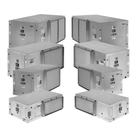
- Page 1 Installation and Maintenance Manual IM 1049-9 Group: WSHP Part Number: 910258820 Date: December 2018 Daikin Enfinity™ Horizontal Water Source Heat Pumps R-410A Refrigerant Model CCH, CCW Unit Sizes 007 – 070...
-
Page 3: Table Of Contents
ontents Model Nomenclature . . . . . . . . . . . . . . . . . . . . . . . . . . 4 Start-up . -
Page 4: Model Nomenclature
odel oMenClature Category Code Item Code Option Code Designation & Description Product Category Water Source Heat Pump Product Identifier CCH = R410A, Ceiling-Mounted, Standard Range CCW = R410A, Ceiling-Mounted, Geothermal Range Design Series (Vintage) D Design E Design Nominal Capacity 7,000 Btuh Nominal Cooling 9,000 Btuh Nominal Cooling 12,000 Btuh Nominal Cooling... -
Page 5: Prior To Installing
rior nstalling Receiving and Storage Pre-Installation To prevent damage, do not operate this equipment CAUTION for supplementary heating and cooling during the construction period. Sharp edges can cause personal injury. Avoid contact with them. Use care and wear protective clothing, safety glasses and gloves Inspect the carton for any specific tagging numbers when handling parts and servicing heat pumps. -
Page 6: Installation Considerations
nstallation onsiderations Unit Location Locate the unit in an area that allows for easy removal of the filter and access panels. Leave a minimum of 18" of clearance around the heat pump for easy removal of the entire unit (if necessary), and to perform routine maintenance, or troubleshooting. Provide sufficient room to make water, electrical and duct connections. -
Page 7: Filter Access
90 degrees and simultaneously rotate Figure 3: Discharge capacitor and release wire clip 180 degrees to achieve the proper orientation. Not all Daikin units will have the same air dis- Capacitor charge location but will have the same general results when following the instructions. - Page 8 nstallation onsiderations Lift the fan assembly out rotating it 180 degrees and Reinstall the access panel in the fan motor access position it within the opening at the end of the unit opening (Figure (Figure 5). With the fan motor in the end discharge Reinstall the top panel and secure with screws position the fan and housing orientation is top- removed previously.
-
Page 9: Ductwork & Attenuation
nstallation onsiderations Ductwork & Attenuation line the last five diameters of duct before each register with a one-inch thick sound blanket. Elbows, tees and Discharge ductwork is normally used with these dampers can create turbulence or distortion in the conditioners. Return air ductwork may also be required. airflow. Place a straight length of duct, 5 to 10 times the All ductwork should conform to industry standards of good duct width, before the next fitting to smooth out airflow. -
Page 10: Ventilation Air
nstallation onsiderations Ventilation Air Return air ductwork can be connected to the standard filter rack. See Figure 9 (side filter removal shown). The Ventilation may require outside air. The temperature of filter rack can be installed for bottom filter removal or the ventilation air must be controlled so that mixture of side filter removal by locating the brackets. For side filter outside air and return air entering the conditioner does removal the brackets should be located on the bottom, not exceed conditioner application limits. -
Page 11: Electrical
leCtriCal Electrical Data Fan Assembly All fan motors are multi-speed PSC or optional ECM General (sizes 015-070) type with integral mounting brackets Verify the compatibility between the voltage and and thermal overload protection. The motor is isolated phase of the available power and that shown on the from the fan housing for minimum vibration transmission. -
Page 12: Unit Installation
nstallation Piping Note: Do not over-torque fittings. The maximum torque without damage to fittings is 30 foot pounds. If a All units should be connected to supply and return torque wrench is not available, use as a rule of piping in a two-pipe reverse return configuration. A thumb, finger tight plus one quarter turn. -
Page 13: Cleaning & Flushing System
nstallation Cleaning & Flushing System Shut off supplemental heater and circulator pump and open all drains and vents to completely drain Prior to first operation of any conditioner, the water down the system. Short circuited supply and return circulating system must be cleaned and flushed of all runouts should now be connected to the conditioner construction dirt and debris. supply and return connections. -
Page 14: Start-Up
tart Start-up Measure the temperature difference between entering and leaving air and entering and leaving Open all valves to full open position and turn on water. With entering water of 60°F to 80°F (16°C to power to the conditioner. 27°C), leaving water should be 6°F to 12°F (3.3°C to 6.6°C) cooler, and the air temperature rise through Set thermostat for “Fan Only”... -
Page 15: Standard Range Units
Perating iMits Typical water source heat pump common design temperatures Table 2: Typical water source heat pump common design temperatures Entering Air °F Entering Water °F Operating Minimum Maximum Standard Range Extended Range Mode Minimum Maximum Minimum Maximum Cooling Heating –... -
Page 16: Controls
ontrols MicroTech III Unit Controller Remote Reset of Automatic Lockouts ® The Remote Reset feature provides the means to The MicroTech III Unit Controller includes built-in remotely reset some lockouts. features such as random start, compressor time delay, shutdown, condensate overflow protection, defrost There are (3) means to reset an automatic lockout cycle, brownout, and LED/fault outputs. - Page 17 ontrols Table 5: MicroTech III unit controller terminals locations H7 – 2 No Connection and descriptions H7 – 3 Red LED Output H1 – 1 24 VAC Power Input H7 – 4 Green LED Output H1 – 2 24 VAC common H7 –...
- Page 18 ontrols Table 7: MicroTech III Controller Status LED's Description Type* Yellow Green Emergency Shutdown Mode Flash Low Voltage Brownout Fault Flash High Pressure (HP1) Fault Flash Low Pressure (LP1) Fault Low Suction Temp (LT1) Sensor Fail Fault Flash Flash Low Suction Temp (LT1) Fault Flash Room Temp Sensor Fail (with Room Sensor Control Only)
- Page 19 ontrols Figure 15: Location of configuration jumpers on the Note: A random start delay time between 300 and 360 MicroTech III unit controller seconds is generated at power up. Figure 14: MicroTech III unit controller terminal locations The IV/PR(H8) terminals of the MicroTech III unit controller are used for motorized valve / pump restart.
-
Page 20: Microtech Iii Controller With L
Module based on a room sensor. ■ Enable fan and compressor operation. This manual covers the installation of a Daikin Horizontal Ceiling Hung Unit - Model CCH, CCW Water Source ■ Monitor all equipment protection controls. Heat Pump. For installation and operation information on Communication Module and other ancillary ■... -
Page 21: Microtech Iii Controller With Bacnet® Communication
MicroTech III Unit Controller with BACnet MS/TP Microtech III Unit Controller Communication Module orchestrates the following unit operations: Daikin water source heat pumps are available with ■ Enable heating and cooling to maintain setpoint Daikin BACnet MS/TP communication module that... - Page 22 ontrols Figure 18: L ® Communication Module Placement on MicroTech™ III Unit Controller orks IM 1049-9 www.DaikinApplied.com...
-
Page 23: Prior To Start-Up
rior tart Changing PSC Fan Motor Speed Unit Sizes 015 and 024 (all available voltages) The fan motor can be changed from high to low speed or vice versa by interchanging the wires on the black and Fan motors on unit sizes 015 and 024 in all available red labeled terminals on the motor terminal block. - Page 24 rior tart Unit Size 042 (575/60/3) Unit Size 048 (380/50/3, 460/60/3, 575/60/3) The fan motor on unit size 042 for voltage 575/60/3 has a five-position terminal block and is factory wired for The fan motor on unit size 048 for voltages 380/50/3, high speed (Figure 23). Low speed can be achieved by 460/60/3 and 575/60/3 have a five-position terminal block interchanging black terminal (3) with red terminal (5) and and are factory wired for low speed...
-
Page 25: (Optional) Ec Motor
rior tart Unit Size 060 (380/50/3, 460/60/3, Unit Size 070 (460/60/3, 575/60/3) 575/60/3) The fan motor on unit size 070 for voltages 460/60/3 and 575/60/3 (Figure 32) have a five-position terminal block The fan motor on unit size 060 for voltages 380/50/3, and are factory wired for high speed. Low speed can be 460/60/3 and 575/60/3 (Figure 29) have a five-position... -
Page 26: Start-Up
tart leaving water. It should be approximately 1-1⁄2 CAUTION times greater than the heating mode temperature difference. For example, if the cooling temperature Units must be checked for water leaks upon initial water system difference is 15°F (8°C), the heating temperature start-up. Water leaks may be a result of mishandling or damage difference should be 10°F (5°C). -
Page 27: Typical Wiring Diagrams
yPiCal iring iagraMs Figure 34: MicroTech III Unit Controller with PSC Motor – 208/230-60-1 Unit Sizes 015-060 Drawing No. 668991202 Wiring diagrams are typical. For the latest drawing version refer to the wiring diagram located on the inside of the controls access panel of the unit. Note: Gray tinted areas in the wiring diagram: Units with factory installed communication module include Discharge Air Temperature (DAT) and Return Air Temperature (RAT) sensors shipped loose and are field installed. - Page 28 yPiCal iring iagraMs Figure 35: MicroTech III Unit Controller with PSC Motor – 208/230/460/575-60-3 Unit Sizes 024-070 Drawing No. 668991202 Wiring diagrams are typical. For the latest drawing version refer to the wiring diagram located on the inside of the controls access panel of the unit. Note: Gray tinted areas in the wiring diagram: Units with factory installed communication module include Discharge Air Temperature (DAT) and Return Air Temperature (RAT) sensors shipped loose and are field installed.
- Page 29 yPiCal iring iagraMs Figure 36: MicroTech III Unit Controller with EC Motor – 208 /230-60-1 Unit Sizes 024-070 Drawing No. 910104890 Wiring diagrams are typical. For the latest drawing version refer to the wiring diagram located on the inside of the controls access panel of the unit.
- Page 30 yPiCal iring iagraMs Figure 37: MicroTech III Unit Controller with EC Motor – 208/230-60-1 Unit Sizes 015-060 Drawing No. 919194871 Wiring diagrams are typical. For the latest drawing version refer to the wiring diagram located on the inside of the controls access panel of the unit.
- Page 31 yPiCal iring iagraMs Figure 38: MicroTech III Unit Controller with EC Motor and Optional Communication Module – 460-60-3 Unit Sizes 024-070 Drawing No. 910102101 Wiring diagrams are typical. For the latest drawing version refer to the wiring diagram located on the inside of the controls access panel of the unit.
-
Page 32: Thermostats & Wall Sensors
& W herMostats ensors Typical Connections For Figure 41: Programmable Electronic Thermostat 3 Heat/2 Cool, 7-Day Programmable, Auto Changeover, Thermostats & Temperature Hardwired – P/N 910193128 & Wi-Fi P/N 910193133 Sensors MicroTech III Controller Terminals TB2 Thermostats & Remote Sensors Used with MicroTech III –Standalone Operation Figure 39: Programmable Electronic Thermostat 2 Heat/2 Cool, 7-Day Programmable, Auto Changeover,... - Page 33 & W herMostats ensors Sensors used with MicroTech III control Figure 43: Programmable & Non-Programmable Electronic Thermostats 2 Heat/2 Cool, Auto Changeover, Hardwired Building Automated System Operation – P/N 910121746 & P/N 910121748 Figure 46: Digitally Adjustable Display Sensor (6-button) WSHP MicroTech III Controller –...
- Page 34 & W herMostats ensors Figure 49: Basic sensor – P/N 910152149 NOTICE MicroTech III Controller Terminals TB1 For 50Hz units, it may be necessary to install a Ferrite Core Noise Suppresor on the thermostat cord cable where it enters the unit “Low Voltage” opening (see Figure 52).
-
Page 35: Additional Accesories
dditional CCesories Motorized Isolation Valve & Relay This version of the control uses VAC relays and should not be used in combination with any other accessories or The motorized valve kit is available as a field-installed equipment that require VDC connections. accessory. Figure 54: Multiple Unit Control Panel and Board Wired as shown in Figure 53, the motorized valve will open... -
Page 36: Maintenance
All Daikin water source heat pumps are designed for commercial use. The units are designed for the cooling mode of opera- tion and fail safe to cooling. -
Page 37: Troubleshooting
roubleshooting MicroTech III Unit Controller LED Faults Table 11: Low Voltage Brownout or Emergency Shutdown Description Type Yellow Green Low Voltage Brownout Fault Flash Emergency Shutdown Mode Flash * Same LED display for both conditions • Verify the E terminal is not connected to common. Remove wire, if connected, and LED should change to solid green only •... -
Page 38: I/O Expansion Module Led Faults (For Units With Optional Boilerless Electric Heat)
roubleshooting MicroTech III Unit Controller LED Faults (Continued) Table 18: Serial EEPROM Corrupted Description Type Yellow Green Serial EEPROM Corrupted Fault • Cycle power to see if problem is corrected • Replace main board, only if problem persists after power cycle Table 19: Service Test Mode Enabled Description Type... - Page 39 roubleshooting I/O Expansion Module LED Faults (For units with optional boilerless electric heat) (continued) Table 26: High Pressure Circuit #2 Description Type Yellow Green High Pressure Circuit #2 Fault Flash • Verify high pressure switch is connected to terminal H6 on the I/O Expansion board •...
- Page 40 roubleshooting Troubleshooting Refrigeration Circuit Figure 56: Troubleshooting Refrigeration Circuit Water Suction Compressor Air Temp (loops) Symptom Head Pressure Super Heat Subcooling Safety Lock Out Pressure Amp Draw Differential Temp Differential Charge Undercharge System High Low Pressure (Possible Leak) Normal Overcharge System High High High...
- Page 41 roubleshooting Troubleshooting the Water Source Heat Pump Unit Figure 57: Troubleshooting Guide - Unit Operation Unit control, check thermostat Low voltage, check Fuse may be blown, Wire may be loose or broken. for correct wiring or faulty power supply voltage circuit breaker is open Replace or tighten wires thermostat...
-
Page 42: Typical Refrigeration Cycles
yPiCal efrigeration yCles Figure 58: Cooling Mode – (Single Circuit Only Shown) Return Air Thermal Co-Axial Heat Expansion Valve Exchanger Water In Coil – Air to Refrigerant Heat Exchanger Water Out Sensing Bulb and Capillary Tube Compressor Blower Reversing Valve Conditioned Air –... -
Page 43: General Use And Information
eneral se and nforMation DANGER To avoid electrical shock, personal injury or death, be sure that field wiring complies with local and national fire, safety, and electrical codes, and voltage to the system is within the limits shown in the job-specific drawings and unit electrical data plate(s). Power supply unit must disconnected... -
Page 44: Start Form
Water Source Heat Pump Equipment Check, Test and Start Form This form must be completed and submitted within ten (10) days of start-up to comply with the terms of the Daikin warranty. Forms should be returned to Daikin Warranty Department. - Page 45 Job Name ___________________________________________________ Check Test Date: __________________________ City __________________________________________________________ State _______________ Zip ______________ Daikin Model # ______________________________________________________ Daikin Serial # _______________________________________ Job site Unit ID # (HP #) _____________________________ General Contractor: _____________________________________ Mechanical Contractor: _____________________________ Technician Performing Start-Up: Name ______________________________ Employer: _____________________________ Complete equipment data from measurements taken at the locatons indicated on the drawing below .
- Page 46 Commercial Check, Test and Start Worksheet (Complete all equipment measurements indicated for each unit per installation on previous page) Check Amps Comments Model Serial # H .P . # Volts Cool- Filter (more comments on next sheet) Coil Part No . _____________________________ IM 1049-9 www.DaikinApplied.com...
- Page 47 Notes / Comments Form WS-CTS-00.01 (Rev. 4/14) www.DaikinApplied.com IM 1049-9...
- Page 48 Daikin Applied Training and Development Now that you have made an investment in modern, efficient Daikin equipment, its care should be a high priority. For training information on all Daikin HVAC products, please visit us at www.DaikinApplied.com and click on Training, or call 540-248-9646 and ask for the Training Department.