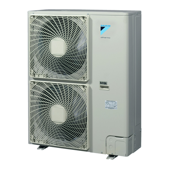
Daikin Altherma ERHQ014BAV3 Installation Manual
Hide thumbs
Also See for Altherma ERHQ014BAV3:
- Installation manual (28 pages) ,
- Installation manual (28 pages) ,
- Installation manual (20 pages)

Related Manuals for Daikin Altherma ERHQ014BAV3


Summary of Contents for Daikin Altherma ERHQ014BAV3
- Page 1 INSTALLATION MANUAL Outdoor unit for air to water heat pump ERHQ011BAV3 ERHQ014BAV3 ERHQ016BAV3 ERHQ011BAW1 ERHQ014BAW1 ERHQ016BAW1 ERLQ011CAV3 ERLQ014CAV3 ERLQ016CAV3 ERLQ011CAW1 ERLQ014CAW1 ERLQ016CAW1...
- Page 2 ERHQ ≥100 ≥100 ≥100 ≥100 ≥100 ≤500 ≥1000 ≥150 ≥150 ≥150 ≤500 ≥1000 B 2 B 2 ≥500 ≤500 ≥500 ≥1000 D 2 D 2 D 2 D 2 ≥100 ≥500 L1<L2 ≥100 ≥500 L2<L1 L 1 L 1 0<L1≤ 1 / 2 H ≥750 ≥1000 ≥250...
- Page 3 3PW57793-1...
-
Page 4: Table Of Contents
ERHQ011BAV3+W1 ERLQ011CAV3+W1 Installation manual Outdoor unit for air to water heat pump ERHQ014BAV3+W1 ERLQ014CAV3+W1 ERHQ016BAV3+W1 ERLQ016CAV3+W1 15. Test operation ................21 ONTENTS Page 15.1. Pre-run checks ................21 1. Definitions.................. 1 15.2. Test run ..................21 15.3. Failure diagnosis at the moment of first installation ..... 22 1.1. -
Page 5: Meaning Of Used Terms
Be sure only to use accessories and optional Sales distributor for products as per the subject of this manual. equipment made by Daikin which are specially designed for use with the products as of subject in this manual and have them installed by Installer: an installer. -
Page 6: Warning
Warning Caution Ask your dealer or qualified personnel to carry out installation Earth the unit. work. Do not install the machine by yourself. Earthing resistance should be according to applicable Improper installation may result in water leakage, electric shocks legislation. or fire. -
Page 7: Before Installation
EFORE INSTALLATION An ERLQ_CA outdoor unit can be connected to an EKHBH/X016* indoor unit (bottom plate heater at WARNING outdoor unit is controlled by the outdoor pcb). All functionalities related to domestic hot water of an Since maximum working pressure for ERHQ is 4.0 MPa or ERLQ_CA are only applicable in combination with an 40 bar and for ERLQ is 4.17 MPa or 41.7 bar, pipes of EKHBH/X016BB indoor unit. -
Page 8: Handling
Possible options Bottom plate heater Drain socket ERLQ Standard Not applicable ERHQ Optional kit Optional kit (a) Factory mounted. (b) Combination of both options is prohibited. (c) No drain socket available for ERLQ. Snow cover Demand pcb ERLQ EK016SNC KRP58M51 (a) This demand pcb option is only applicable for the "setting of demand running"... -
Page 9: Main Components
4.2. Main components Heat exchanger Accumulator Fan motor Terminal communication and power supply Reactor coil(s) Gas stop valve 4-way valve Liquid stop valve Noise filter pcb (only for V3 models) Electronic expansion valve (main) Service pcb (only for V3 models) Solenoid valve (hot gas pass)(only for ERLQ) Pressure sensor Compressor... -
Page 10: Functional Diagram Erhq_V3+W1
4.3. Functional diagram ERHQ_V3+W1 M1F-M2F S1PH E1HC M1F-M2F S1PH E1HC Indoor unit EKHBH/X016 Stop valve (with service port 5/16") Outdoor unit Crank case heater Heat exchanger Fan motor Service port 5/16" Injection valve Compressor Capillary tube Accumulator Thermistor (air) Pressure sensor Thermistor (discharge) High pressure switch Thermistor (suction) -
Page 11: Functional Diagram Erlq_V3+W1
4.4. Functional diagram ERLQ_V3+W1 M1F-M2F S1PH E1HC Indoor unit EKHBH/X016 Crank case heater Outdoor unit Fan motor Heat exchanger Electronic expansion valve (injection) Service port 5/16" Capillary tube Compressor Solenoid valve (hot gas pass) Accumulator Thermistor (air) Pressure sensor Thermistor (discharge) High pressure switch Thermistor (suction) 4-way valve... -
Page 12: Selecting Installation Site
Install a baffle plate on the air suction side of the outdoor unit ELECTING INSTALLATION SITE and set the outlet side at a right angle to the direction of the wind: 5.1. General CAUTION Make sure to provide for adequate measures in order to prevent that the outdoor unit be used as a shelter by small animals. -
Page 13: Selecting A Location In Cold Climates
5.2. Selecting a location in cold climates For ERLQ only. Follow the procedure as described below for modifying the position of the air thermistor (R1T). The thermistor Refer to "3.4. Model identification" on page fixture is delivered in the accessory bag. Spare thermistor fixing plate is delivered in the NOTICE accessory bag. -
Page 14: Precautions On Installation
RECAUTIONS ON INSTALLATION NOTICE If drain holes of the outdoor unit are covered by a mounting base or by floor surface, raise the unit in order to provide a free space of more than 100 mm under the outdoor unit. 6.1. -
Page 15: Installation Method For Prevention Of Falling Over
6.3. Installation method for prevention of falling over In case obstacles exist in front of the air inlet. If it is necessary to prevent the unit from falling over, install as shown in the figure. prepare all 4 wires as indicated in the drawing unscrew the top plate at the 4 locations indicated A and B put the screws through the nooses and screw them back tight ≥300... -
Page 16: Refrigerant Pipe Size And Allowable Pipe Length
8.3. Allowable pipe length and height difference EFRIGERANT PIPE SIZE AND ALLOWABLE PIPE LENGTH See the table below concerning allowable lengths and heights. Refer figure 2. Assume that the longest line in the figure corresponds with the actual longest pipe, and the highest unit in the figure DANGER corresponds with the actual highest unit. -
Page 17: Precautions On Refrigerant Piping
When loosening a flare nut, always use two wrenches together. RECAUTIONS ON REFRIGERANT PIPING When connecting the piping, always use a spanner and torque wrench together to tighten the flare nut to prevent flare nut Do not allow anything other than the designated refrigerant to cracking and leaks. -
Page 18: Stop Valve Operation
9.3. Stop valve operation Cautions on handling the stem cap The stem cap is sealed where Cautions on handling the stop valve indicated by the arrow. Take care not Make sure to keep both stop valves open during operation. to damage it. The figure below shows the name of each part required in After handling the stop valve, make handling the stop valve. -
Page 19: Preventing Foreign Objects From Entering
When passing electrical wiring through the knockout holes, remove any burrs from the knockout holes and wrap the wiring with protective tape to prevent damage. Knockout hole Burr Packing materials 10.1. Preventing foreign objects from entering Plug the pipe through-holes with putty or insulating material Compressor (procured locally) to stop up all gaps, as shown in the figure. -
Page 20: Leak Test And Vacuum Drying
11. L 11.4. Vacuum drying EAK TEST AND VACUUM DRYING To remove all moisture from the system, proceed as follows: When all piping work is complete and the outdoor unit is connected to the indoor unit, it is necessary to: Evacuate the system for at least 2 hours to a target vacuum of –100.7 kPa. -
Page 21: Precautions And General Guidelines
12.3. Calculating the additional refrigerant charge for To avoid compressor breakdown. Do not charge the refrigerant more than the specified amount. ERHQ models This outdoor unit is factory charged with refrigerant and depending on pipe sizes and pipe lengths some systems require NOTICE additional charging of refrigerant. -
Page 22: Complete Recharging
12.5. Complete recharging The pump down operation is now finished. The remote controller may display " U4 " and the indoor pump may continue operating. This is not a malfunction. Even when the ON button on the NOTICE remote controller is pressed, the unit will not start to operate. To restart operation of the unit turn off the main power supply Before recharging, make sure to execute vacuum drying of switch and turn it on again. -
Page 23: Connecting Power Supply And Interunit Wiring
As this unit is equipped with an inverter, installing a phase advancing capacitor not only will deteriorate power factor improvement effect, but also may cause capacitor abnormal heating accident due to high-frequency waves. Therefore, never install a phase advancing capacitor. CAUTION Be sure to install the required fuses or circuit breakers. -
Page 24: Electrical Characteristics
15. T Refer to the installation manual attached to the indoor unit for EST OPERATION wiring of indoor unit, etc. Attach an earth leakage circuit breaker and fuse to the power DANGER supply line. (See figure 6) Never leave the unit unattended during installation or Earth leakage circuit breaker servicing. -
Page 25: Failure Diagnosis At The Moment Of First Installation
15.3. Failure diagnosis at the moment of first 16. M AINTENANCE AND SERVICING installation In case nothing is displayed on the remote controller (the current 16.1. Service precautions set temperature does not display), check for any of the following abnormalities before you can diagnose possible malfunction In order to ensure optimal operation of the unit, a number of checks codes. -
Page 26: Unit Specifications
18. U NIT SPECIFICATIONS OTES 18.1. Technical specifications ERHQ_V3 ERHQ_W1 ERLQ_V3 ERLQ_W1 Casing material Painted galvanised steel 1170 x Dimensions h x w x d (mm) 1345 x 900 x 320 900 x 320 Weight (kg) Operation range • cooling (min./max.) (°C) 10/46 •... -
Page 27: Wiring Diagram
19. W IRING DIAGRAM : Wire clamp : Live : Terminal strip : Neutral : Connector : Relay connector : Black : Orange : Field wiring : Blue : Red : Protective earth screw : Brown : White : Noiseless earth : Green : Yellow NOTE 1... - Page 28 NOTES NOTES...
- Page 29 NOTES NOTES...
- Page 30 NOTES NOTES...
- Page 31 W1-type V3-type 3N~ 50 Hz 1~ 50 Hz 230 V 400 V R410A 16 16a OTES...
- Page 32 4PW57794-1 08.2010...