Advertisement
Quick Links
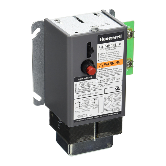
APPLICATION
The R8184M Protectorelay control provides automatic,
nonrecycling control of combination oil burner heating and
cooling systems when used with a C554A Cadmium Sulfide
(cad cell) Flame Detector and low voltage thermostat. It
includes a 40 VA transformer to power a cooling contactor
and fan relay during the cooling operation.
ELECTRICAL RATINGS:
Load Relay Contact Ratings:
Full Load: 7.4A
Locked Rotor: 44.4A
Transformer:
Primary Voltage: 120V, 60 Hz.
Secondary Voltage: 26.5V, 60 Hz.
Ignition Rating: 360 VA in addition to the load relay contact
rating.
Power Consumption:
Start: 9.0A
Running: 5.5A
INSTALLATION
WHEN INSTALLING THIS PRODUCT...
1. Read these instructions carefully. Failure to follow them
could damage the product or cause a hazardous condition.
2. Check the ratings given in these instructions and on the
product to ensure the product is suitable for your application.
3. Ensure the installer is a trained, experienced service
technician.
4. After completing installation, use these instructions to
check product operation.
R8184M PROTECTORELAY
CONTROL
F
CAD
CELL
F
D.T.
11-90
COOLING
CONTACTOR
K1
SS
R1
SAFETY
SWITCH
HEATER
R2
TRIAC
BILATERAL
SWITCH
CAPACITOR
1 USED FOR 4 AMP THERMOSTAT ONLY.
Fig. 1—Wiring diagram of R8184M.
CHOOSE LOCATION
• Mount the R8184M on a 4 x 4 inch junction box, directly
on the burner housing, or inside the appliance cabinet.
• In replacement applications, mount the R8184M in the
same location as the old control.
• Make all line voltage connections in a wiring enclosure
such as a junction box or the appliance wiring compart-
ment.
• Ensure operating temperatures at the selected loca-
tion are between -40° F and 130° F [-40° C and 54° C].
MAKE WIRING CONNECTIONS AND MOUNT R8184M
1. Ensure all wiring complies with local codes and ordi-
nances.
2. Make line voltage connections as shown in Fig. 1.
• Splice leads with solderless connectors.
• Do not exceed load ratings shown on device label.
• Leave enough slack in the wires to permit easy
3. Mount the R8184M to the junction box. Refer to Fig. 2.
4. Connect the C554A Cadmium Sulfide Cell (ordered
separately) leadwires to the F-F terminals on the terminal
strip.
5. Connect all remaining low voltage wiring connections
as shown in Fig. 1.
NOTE: Y and G terminals are provided to simplify connec-
tions of cooling equipment; they are not connected to the
internal circuitry of the R8184M.
THERMOSTAT
FAN RELAY
R
W
C
R
Y
G
(T)
(T)
BROWN
1K1
BLUE
RED
BLACK
R4
LOCKOUT
1
INDICATOR
LIGHT
SS
R8184M PROTECTORELAY
OIL BURNER CONTROL
access into the junction box.
W
Y
G
JUNCTION
BOX
WHITE
1K2
ORANGE
BLACK
L2
BURNER
OIL VALVE
IGNITION
L1
LIMIT
(HOT)
M1559
Form Number 69-0613
© Honeywell Inc. 1990
Advertisement

Related Manuals for Honeywell R8184M


Summary of Contents for Honeywell R8184M
- Page 1 OIL BURNER CONTROL CHOOSE LOCATION APPLICATION • Mount the R8184M on a 4 x 4 inch junction box, directly The R8184M Protectorelay control provides automatic, on the burner housing, or inside the appliance cabinet. nonrecycling control of combination oil burner heating and •...
- Page 2 CHECK SAFETY FEATURES SERVICE Simulate flame failure: The R8184M is set at the factory and requires no adjust- 1. Follow the starting procedure to turn on the main burner. ment or periodic maintenance. The R8184M contains no 2. Close the hand valve in the oil supply line.