Advertisement
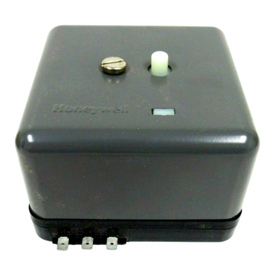
The R4795A Protectorelay™ Primary Control
provides solid state electronic flame safeguard
protection for commercial and industrial gas or oil
burners. It provides a prepurge period before each
start, and intermittent pilot.
120V models meet the requirements of Underwrit-
ers Laboratories Inc. Standard 795 for mechanical
draft and atmospheric burner inputs from 400,000 to
2,500,000 Btu.
Meets Underwriters Laboratories Inc. requirements
for oil burner group 8 when 30, 60, or 90 second pre-
purge timer is used.
Selection of solid state, plug-in prepurge timers pro-
vides 7, 10, 30, 60, or 90 second prepurge time.
Includes terminals for connection of air flow switch
to prove airflow before prepurge period starts, dur-
ing purge, and during the entire Run period.
Choice of interchangeable, color-coded, solid state,
plug-in flame signal amplifiers allows use with rec-
tification or ultraviolet type flame detectors.
Safe-start feature prevents start when flame or flame
simulating condition is present.
Recycles through prepurge if the flame goes out
while burner is running. If pilot flame is not re-
established, safety switch trips and locks out system.
A tripped safety switch must be manually reset to
restore operation.
Push-to-reset safety switch is dust-resistant enclosed.
Optional spdt alarm contacts operate external alarm
on safety switch lockout.
Ignition interference circuit (rectification amplifier
only) protects electronic network from high voltage
ignition crossover and provides visual indication
when interference occurs.
S.Y. • Rev. 12-94 • ©Honeywell Inc. 1994
Flame Safeguard
Primary Controls
Solid state circuitry eliminates vacuum tube replace-
ment and increases resistance to vibration. Applica-
tion of power not required during Off cycle; no tube
warmup before starting.
Easy-to-replace plug-in components result in faster
service and reduced inventory.
Flame current jack, located on the amplifier, provides
means of plugging in a microammeter to measure the
flame signal with system operating.
Easy mounting and removal through use of captive
mounting screws, which also serve as electrical
connections.
Durable thermoplastic mounting base.
Models available with -40°F (-40°C) temperature
rating.
CONTENTS
Specifications ................................................. 2
Ordering Information ..................................... 2
Installation ..................................................... 4
Checkout ......................................................... 8
Operation ..................................................... 11
Troubleshooting ........................................... 11
Service .......................................................... 13
1
R4795A
60-2285-7
60-2285-7
Advertisement

Related Manuals for Honeywell R4795A


Summary of Contents for Honeywell R4795A
-
Page 1: Table Of Contents
Operation ............. 11 Ignition interference circuit (rectification amplifier Troubleshooting ........... 11 only) protects electronic network from high voltage Service ............13 ignition crossover and provides visual indication when interference occurs. S.Y. • Rev. 12-94 • ©Honeywell Inc. 1994 60-2285—7 60-2285-7... -
Page 2: Specifications
If you have additional questions, need further information, or would like to comment on our products or services, please write or phone: 1. Your local Honeywell Home and Building Control sales office (check white pages of phone directory). 2. Home and Building Control Customer Logistics Honeywell Inc., 1985 Douglas Drive North... - Page 3 -40°F (-40°C) rated models; file response. no. LR95329. R7290A1019 Amplifier: 0.8 sec nominal flame failure Factory Mutual Approved: R4795A 120V models; re- response. port no. 18774. -40°F (-40°C) rated models; report R7290A1027 Amplifier: 3 sec nominal flame failure no.
-
Page 4: Installation
INSTALLATION Installation CAUTION Vibration Do not install the R4795A where it could be subject to 1. Installer must be a trained, experienced, flame excessive vibration. Vibration shortens the life of the elec- safeguard control service technician. tronic and mechanical components. - Page 5 5. For ignition installations in a contaminating environ- 2ND STAGE ment, use Honeywell Specification no. R1239001 High Ten- BURNER OIL VALVE(S) MOTOR sion Ignition Cable or equivalent. This wire is very resistant...
- Page 6 Replacing RA890E,F,G with R4795A R4795C Replacement 1. Disconnect all wires from terminal 1, and splice with In most cases, the R4795A can directly replace the solderless connector. (If RA890 has no terminal 1 wiring, R4795C. For standing pilot applications where the pilot disregard this step.)
- Page 7 R4795A INSTALLATION Fig. 6—Flame detector wiring. Fig. 7—Alarm terminal connections. PHOTOCELL FLAME ROD ALARM TERMINALS (OPTIONAL) R4795 C7012 ULTRAVIOLET DETECTOR N.O. N.C. (HOT) ALARM POWER SUPPLY LINE OR LOW VOLTAGE ALARM IF A LINE VOLTAGE ALARM IS USED, THE R4795 MUST BE BLUE MOUNTED IN A SUITABLE ENCLOSURE.
-
Page 8: Checkout
Make certain that: 1. Wiring connections are correct and all terminal screws are tight. Use a meter to check the continuity of all circuits. Fig. 9—Internal components of R4795A. 2. Flame detector is installed and positioned properly. Consult the appropriate installation instructions. - Page 9 R4795A CHECKOUT FLAME CURRENT CHECK 2. The flame current is at least two microamperes for The flame current check is the best indicator of proper R7289A Rectification Amplifier (color-coded green), or at flame detector application. Perform the check at the time of least 1.5 microamperes for an R7290A Ultraviolet Amplifier...
- Page 10 R4795A CHECKOUT 4. If relay 2K does pull in, resight the detector farther out CAUTION from the spark, or away from possible reflection. It may be necessary to construct a barrier to block the ignition spark Do not manually push in the relays.
-
Page 11: Operation
2K2. Contact 1K1 closes to energize the safety switch heater. Flame Proven (Pilot or First Stage R4795A: Relay 2K pulls in. Contact 2K2 opens to cut off ignition, contact 2K3 Oil) closes to energize the main fuel valve(s) or second stage oil valve(s). Contact 2K1 opens to de-energize the safety switch heater and reset the purge timer. - Page 12 R4795A TROUBLESHOOTING F. Pilot lights and relay 2K pulls in but the main burner 3. Check the position of the flame relay. If relay 2K is does not light. pulled in, check for flame simulating condition. G. Relay 2K remains in after flame is extinguished.
-
Page 13: Service
R4795A TROUBLESHOOTING • SERVICE (3) Remove any flame simulating condition such How detected. The arc gap circuit in the rectifica- as false light. tion amplifier (Fig. 10) protects the R4795 from igni- (4) Note that any change made in the detector or its tion interference;... - Page 14 1. Do not clean contacts unless absolutely necessary. dirt. The residue will also break down to form various 2. Use only Honeywell Contact Cleaner part no. 132569. carbonaceous products. Either result will cause early contact Do not use any other type of contact cleaner.
- Page 15 60-2285—7...
- Page 16 Home and Building Control Home and Building Control Honeywell Inc. Honeywell Limited—Honeywell Limitée 1985 Douglas Drive North 740 Ellesmere Road Golden Valley, MN 55422 Scarborough, Ontario M1P 2V9 Printed in Mexico. www.honeywell.com/bbc...