Table of Contents
Advertisement
Quick Links
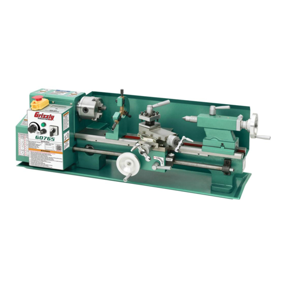
MODEL G0765
7" X 14" BENCHTOP LATHE
OWNER'S MANUAL
(For models manufactured since 5/15)
COPYRIGHT © MARCH, 2014 BY GRIZZLY INDUSTRIAL, INC. REVISED FEBRUARY, 2018 (HE)
WARNING: NO PORTION OF THIS MANUAL MAY BE REPRODUCED IN ANY SHAPE
OR FORM WITHOUT THE WRITTEN APPROVAL OF GRIZZLY INDUSTRIAL, INC.
#BLTSDM16229 PRINTED IN CHINA
V2.02.18
Advertisement
Table of Contents

Related Manuals for Grizzly G0765


Summary of Contents for Grizzly G0765
- Page 1 OWNER'S MANUAL (For models manufactured since 5/15) COPYRIGHT © MARCH, 2014 BY GRIZZLY INDUSTRIAL, INC. REVISED FEBRUARY, 2018 (HE) WARNING: NO PORTION OF THIS MANUAL MAY BE REPRODUCED IN ANY SHAPE OR FORM WITHOUT THE WRITTEN APPROVAL OF GRIZZLY INDUSTRIAL, INC.
- Page 2 This manual provides critical safety instructions on the proper setup, operation, maintenance, and service of this machine/tool. Save this document, refer to it often, and use it to instruct other operators. Failure to read, understand and follow the instructions in this manual may result in fire or serious personal injury—including amputation, electrocution, or death.
-
Page 3: Table Of Contents
Identification ........... 3 Machine Storage .......... 51 Controls & Components ......... 4 SECTION 7: SERVICE ........52 G0765 Data Sheet ......... 6 Troubleshooting ........... 52 SECTION 1: SAFETY ........8 Backlash Adjustment ........54 Safety Instructions for Machinery ....8 Leadscrew End-Play Adjustment .... -
Page 4: Introduction
If you find this to be the case, and the difference between the manual and machine leaves you The G0765 features an electronic variable-speed confused or unsure about something, check our website for an updated version. We post current... -
Page 5: Identification
Identification Become familiar with the names and locations of the controls and features shown below to better understand the instructions in this manual. Figure 1. Model G0765 identification. A. On/Off Switch w/Emergency Stop Button M. Compound Rest Handwheel B. Power Light N. -
Page 6: Controls & Components
Button is reset, and On button is pressed. D. Spindle Switch: Starts, stops, and reverses spindle rotation. E. Fuse: Protects control panel in case of an electrical overload. Variable Speed Dial: Controls the variable speed of the spindle. Model G0765 (Mfd. Since 5/15) - Page 7 (1 of Gears Figure 6. End gear components. Configuring the end gears (shown in Figure 6) controls the speed of the leadscrew for thread- ing or power feed operations. Model G0765 (Mfd. Since 5/15)
-
Page 8: G0765 Data Sheet
MACHINE DATA SHEET Customer Service #: (570) 546-9663 · To Order Call: (800) 523-4777 · Fax #: (800) 438-5901 MODEL G0765 7" X 14" VARIABLE‐SPEED BENCHTOP LATHE Product Dimensions: Weight................................88 lbs. Width (side-to-side) x Depth (front-to-back) x Height................30 x 9 x 10 in. - Page 9 The information contained herein is deemed accurate as of 2/21/2018 and represents our most recent product specifications. Model G0765 PAGE 2 OF 3 Due to our ongoing improvement efforts, this information may not accurately describe items previously purchased. Model G0765 (Mfd. Since 5/15)
-
Page 10: Section 1: Safety
Everyday ery. Never operate under the influence of drugs or eyeglasses are NOT approved safety glasses. alcohol, when tired, or when distracted. Model G0765 (Mfd. Since 5/15) - Page 11 EXPERIENCING DIFFICULTIES. If at any time debris. Make sure they are properly installed, you experience difficulties performing the intend- undamaged, and working correctly BEFORE ed operation, stop using the machine! Contact our operating machine. Technical Support at (570) 546-9663. Model G0765 (Mfd. Since 5/15)
-
Page 12: Additional Safety For Metal Lathes
MEASURING WORKPIECE. To reduce risk of cradle or piece of plywood over the bed ways. Use lifting equipment, as necessary, for large chucks. entanglement, never measure rotating workpieces. -10- Model G0765 (Mfd. Since 5/15) -
Page 13: Additional Chuck Safety
Always disconnect the lathe from power additional training from an experienced chuck user before performing these procedures. before using a chuck. -11- Model G0765 (Mfd. Since 5/15) -
Page 14: Section 2: Power Supply
To reduce the risk of these hazards, avoid over- ensure circuit is properly sized for safe operation. loading the machine during operation and make sure it is connected to a power supply circuit that meets the specified circuit requirements. -12- Model G0765 (Mfd. Since 5/15) - Page 15 Two-prong outlets do not meet the grounding requirements for this machine. Do not modify or use an adapter on the plug provided—if it will not fit the outlet, have a qualified electrician install the proper outlet with a verified ground. -13- Model G0765 (Mfd. Since 5/15)
-
Page 16: Section 3: Setup
IMPORTANT: Save all packaging materials until you are completely satisfied with the machine and have resolved any issues between Grizzly or the shipping agent. You MUST have the original pack- aging to file a freight claim. It is also extremely helpful if you need to return your machine later. -
Page 17: Inventory
Often, these items get — Change Gear (45-tooth) ......1 lost in packaging materials while unpack- — Change Gear (50-tooth) ......1 ing or they are pre-installed at the factory. — Change Gear (55-tooth) ......1 -15- Model G0765 (Mfd. Since 5/15) -
Page 18: Cleanup
Figure 12. T23692 Orange Power Degreaser. Repeat Steps 2–3 as necessary until clean, then coat all unpainted surfaces with a quality metal protectant to prevent rust. -16- Model G0765 (Mfd. Since 5/15) -
Page 19: Site Considerations
Shadows, glare, or strobe effects that may distract access restricted location. or impede the operator must be eliminated. " Lathe Keep " Workpiece Loading Area Unobstructed = Electrical Connection Illustration Not To Scale Figure 13. Minimum working clearances. -17- Model G0765 (Mfd. Since 5/15) -
Page 20: Lifting & Placing
With the exception of the handwheel handles, the the receptacle. lathe is shipped fully assembled. Thread the handles into the cross slide handwheel and carriage handwheel, (see Figure 14). Cross Slide Handwheel Carriage Handle Figure 14. Handwheel handles installed. -18- Model G0765 (Mfd. Since 5/15) -
Page 21: Test Run
Note: If a chuck is not installed on the lathe, you do not need to install one for this test run. Emergency Stop Button Spindle Direction Variable Speed Dial Switch Set to "0" Set to "0" Figure 15. Headstock controls. -19- Model G0765 (Mfd. Since 5/15) - Page 22 Congratulations! The test run is complete. Turn The spindle speed display and power button lathe OFF and perform the following Spindle should illuminate to indicate that lathe is con- Break-In procedure. nected to power supply. -20- Model G0765 (Mfd. Since 5/15)
-
Page 23: Spindle Break-In
Run lathe in reverse at 2000 RPM for 10 min- utes, then turn speed dial to "0", turn spindle direction switch to "0", and press Emergency Stop button. Congratulations! Spindle break-in is complete. -21- Model G0765 (Mfd. Since 5/15) -
Page 24: Section 4: Operations
Stop button, then removes workpiece. formal training before beginning any proj- ects. Regardless of the content in this sec- tion, Grizzly Industrial will not be held liable for accidents caused by lack of training. -22- Model G0765 (Mfd. Since 5/15) -
Page 25: Chuck & Faceplate Mounting
With the correct clamping hardware, a faceplate offers a wide range of uses, including machining non- concentric workpieces, straight turning between centers, off-center turning, and boring. -23- Model G0765 (Mfd. Since 5/15) -
Page 26: Chuck Installation
Use an appropriate device to protect ways dur- ing installation process (refer to Installation & Removal Device on Page 25). Figure 21. Chuck secured against backplate. Thoroughly clean and wipe-down all mating surfaces with a lightly-oiled, lint-free rag. -24- Model G0765 (Mfd. Since 5/15) -
Page 27: Scroll Chuck Clamping
Bar Stock Unsafe Jaw Position CORRECT INCORRECT Unsafe Jaw Position Safer Inside Jaw Use Figure 24. Jaw guide and jaw numbers. Cylinder Poor Scroll CORRECT Gear Engagement INCORRECT Figure 22. Jaw selection and workpiece holding. -25- Model G0765 (Mfd. Since 5/15) - Page 28 Rotate chuck key clockwise until you see tip of outer scroll-gear lead thread about to enter a jaw guide (see below). Lead Thread Figure 25. Lead thread on scroll gear. -26- Model G0765 (Mfd. Since 5/15)
-
Page 29: Faceplate
To reduce this risk, use a minimum of THREE independent clamping devices to hold workpiece onto faceplate. Clamp Faceplate Figure 26. Example of a workpiece clamped in a faceplate. -27- Model G0765 (Mfd. Since 5/15) -
Page 30: Tailstock
Tailstock Lock Lever Quill Lock Tighten quill lock lever. Lever Quill Offset Adjustment Quill Screw (1 of 2) Handwheel Figure 27. Tailstock controls and features. -28- Model G0765 (Mfd. Since 5/15) - Page 31 Offsetting the quill toward the front of the lathe results in a taper at the tailstock end. Conversely, offsetting the quill toward the back of the lathe results in a taper at the spindle end. -29- Model G0765 (Mfd. Since 5/15)
- Page 32 (see Figure below). Figure 32. Turning a dead center. Turn Turn Turn Turn Figure 31. Example of set screw adjustment in relation to tailstock movement. Tighten tailstock lock to secure the offset. -30- Model G0765 (Mfd. Since 5/15)
- Page 33 Mount test or dial indicator so plunger is on tailstock quill. Move tailstock toward back of lathe amount of taper. Figure 35. Adjust tailstock away from the operator. Repeat Steps 5–7 until desired accuracy is achieved. -31- Model G0765 (Mfd. Since 5/15)
-
Page 34: Centers
To remove center from the spindle, insert a piece of round bar stock (or similar tool) through outside end of spindle. Hold onto center with gloved hand or shop rag, then tap bar stock to knock center loose. -32- Model G0765 (Mfd. Since 5/15) - Page 35 Also, over-tightening will result in excessive friction and heat, which may damage the workpiece or center. -33- Model G0765 (Mfd. Since 5/15)
-
Page 36: Steady Rest
Finger lock nuts. Adjustment Finger Knob Lubricate finger tips with an anti-seize lubri- cant during operation. Finger Lock Nut Note: Mill or file tips if they show wear. Lock Figure 40. Steady rest components. -34- Model G0765 (Mfd. Since 5/15) -
Page 37: Compound Rest
2.5 x 0.5" = 1.25"). you need to cut threads. Firmly secure cutting tool with at least two tool post screws. Check and adjust cutting tool to spindle cen- terline, as instructed in next subsection. -35- Model G0765 (Mfd. Since 5/15) - Page 38 (Side View) cedure. For this to work, the tailstock must be aligned to the spindle centerline (refer to Aligning Tailstock To Spindle Centerline for detailed instructions). Figure 44. Cutting tool aligned to the tailstock center. -36- Model G0765 (Mfd. Since 5/15)
-
Page 39: Manual Feed
Set the compound rest angle by hand-rotating it and securing in place with two cap screws. The compound rest has an indirect-read graduated dial. -37- Model G0765 (Mfd. Since 5/15) - Page 40 ON button, then turn the variable speed dial clockwise until the desired spindle speed dis- plays on the spindle speed display. Emergency Stop Button Variable Speed Dial Spindle Speed Display Spindle Direction Switch Figure 48. Spindle speed and direction controls. -38- Model G0765 (Mfd. Since 5/15)
-
Page 41: Power Feed
Figure 51. Half nut lever. C. Half Nut Lever: Engages/disengages half nut for power feed operations. To avoid potential carriage/chuck crash, disengage half-nut lever immediately after Figure 49. Spindle switch. completing power feeding operations. -39- Model G0765 (Mfd. Since 5/15) - Page 42 Replace A and C gears with 20T gears, and B and D gears with 80T gears (see Figure 55 on Page 43). The printed gear letters should face outward. -40- Model G0765 (Mfd. Since 5/15)
-
Page 43: End Gears
B Gear A Gear Gear (80T) (20T) A (20T) B (80T) C (20T) C Gear Gear Gear D (80T) (20T) Figure 57. Secondary threading configuration. D Gear (80T) Figure 55. Power feed end gear configuration. -41- Model G0765 (Mfd. Since 5/15) - Page 44 C gear will not mesh with any of the other (gears removed for clarity). gears in this 20 TPI threading setup. Note: Depending upon configuration, C gear may not be 20T, as shown in Figure 59. -42- Model G0765 (Mfd. Since 5/15)
- Page 45 10. Slide 65T B gear onto keyed bushing and en adjuster hex nut and B/C gear shaft hex firmly against C gear. nut. 14. Secure gears with cap screws and washers removed earlier. 15. Re-install end cover. -43- Model G0765 (Mfd. Since 5/15)
-
Page 46: Threading
Move high/low range lever to low, and move feed direction lever all the way up, as shown in Figure 64. Figure 64. Lever and dial settings for 20TPI. The lathe is now set up to cut 20 TPI threads. -44- Model G0765 (Mfd. Since 5/15) - Page 47 The operator returns the carriage for the next pass and re-engages the half nut using the same thread dial setting to resume Figure 67. Thread dial chart. the cut in the previous pass. -45- Model G0765 (Mfd. Since 5/15)
- Page 48 (see example in Figure 69). 13, 19 Thread Dial Dial Number 12, 20, 28, 36, 44, Figure 71. Example of odd numbered inch 1, 3,5, 7 thread pitch. Figure 69. Example of inch thread pitch divisible by 4. -46- Model G0765 (Mfd. Since 5/15)
-
Page 49: Section 5: Accessories
To reduce this risk, only install accessories recommended for this machine by Grizzly. NOTICE Refer to our website or latest catalog for additional recommended accessories. -
Page 50: Section 6: Maintenance
(Page 52). able to rust if left unprotected. Use a quality ISO • Disengage the half nut on the carriage (to 68 way oil (see Page 49 for offerings from Grizzly) prevent crashes upon startup). to prevent corrosion. -48-... -
Page 51: Lubrication
Failure to follow reasonable lubrication practices as instructed in this manual could Ball Oilers lead to premature failure of lathe compo- nents and will void the warranty. Figure 75. Ball oilers. -49- Model G0765 (Mfd. Since 5/15) - Page 52 Leadscrew & Carriage Rack Bedways Oil Type ..Grizzly SB1365 or ISO 68 Equivalent Oil Type ..Grizzly SB1365 or ISO 68 Equivalent Amount ..........As Needed Amount ..........As Needed Lubrication Frequency ......... Daily Lubrication Frequency ......... Daily Before lubricating the bedways (see Figure 76), Before lubricating the leadscrew and carriage clean them with mineral spirits.
-
Page 53: Machine Storage
Tumbler Gears Oil Type ..Grizzly SB1365 or ISO 68 Equivalent Slide carriage, tailstock, and steady rest Amount ..........2-3 Drops down lathe bed to make sure that way spot- Lubrication Frequency ......Annually ting is not beginning to occur. -
Page 54: Section 7: Service
5. Replace/sharpen cutting tool; index tool to spindle centerline; use correct feed rate and cutting RPM. 6. Workpiece or chuck at fault. 6. Properly secure or center workpiece in chuck or faceplate; replace defective chuck. -52- Model G0765 (Mfd. Since 5/15) - Page 55 (see Page 32). Chuck jaws will 1. Chips lodged in jaws or scroll plate. 1. Remove jaws, clean and lubricate scroll plate, then not move or do not replace jaws. move easily. -53- Model G0765 (Mfd. Since 5/15)
-
Page 56: Backlash Adjustment
Tighten retaining nut with your fingers so it Outer Cap just contacts end bracket, then back nut off Screws ⁄ turn. Hold nut in position and tighten set screw Figure 80. Cross slide backlash adjustment cap against leadscrew until snug. screw. -54- Model G0765 (Mfd. Since 5/15) -
Page 57: Gib Adjustment
DISCONNECT LATHE FROM POWER! Loosen three hex nuts on side of cross slide or compound slide (see Figures 82–83). Cross Slide Adjustment Fasteners Figure 82. Cross slide gib adjustment hex nuts and cap screws. -55- Model G0765 (Mfd. Since 5/15) -
Page 58: Half Nut Adjustment
The adjustment is cor- rect when half nut firmly and easily engages leadscrew while opening and closing. Repeat Steps 3–4, if necessary, until satis- fied with feel of half nut engagement. -56- Model G0765 (Mfd. Since 5/15) -
Page 59: Brush Replacement
(see Figure 86). Screws Figure 88. Front brush components removed. Install new brushes. Re-install brush caps. Replace rear motor cover. Brush Cap Figure 86. Location of rear motor brush cap. -57- Model G0765 (Mfd. Since 5/15) -
Page 60: Timing Belt Tension & Replacement
Black Fine-Tip Felt Marker ........ 1 sure, loosen motor mount hex nuts, and adjust tension until it is correct. Perform Steps 9–11 on Page 61 to re-install components you removed earlier. -58- Model G0765 (Mfd. Since 5/15) - Page 61 Loosen motor mount hex nuts shown in 11. Re-install electrical cabinet, rear motor cover, Figure 92. and end cover. Motor Mount Hex Nuts Figure 92. Location of motor mount hex nuts. -59- Model G0765 (Mfd. Since 5/15)
-
Page 62: Section 8: Wiring
Technical source. Support at (570) 546-9663. The photos and diagrams included in this section are best viewed in color. You can view these pages in color at www.grizzly.com. -60- Model G0765 (Mfd. Since 5/15) -
Page 63: Control Panel Wiring
REV A 09111 CIRCUIT BOARD Front of Control Panel Bottom of Control Panel To Motor CIRCUIT BOARD Page 65 To Speed 4 3 2 1 Sensor Page 65 READ ELECTRICAL SAFETY -61- Model G0765 (Mfd. Since 5/15) ON PAGE 62! -
Page 64: Control Panel Wiring Photos
Control Panel Wiring Photos Figure 96. Control panel wiring (top). Figure 94. G0765 wiring overview. Figure 95. Control panel wiring (bottom). Figure 97. Control panel wiring (front). READ ELECTRICAL SAFETY -62- Model G0765 (Mfd. Since 5/15) ON PAGE 62! -
Page 65: Motor/Speed Sensor/ Plug Wiring
Figure 99. Speed sensor location. SPEED SENSOR To Control Panel Page 63 Wires connect on back side of circuit board Figure 100. Speed sensor wiring. Neutral 110 VAC 5-15 Plug Ground READ ELECTRICAL SAFETY -63- Model G0765 (Mfd. Since 5/15) ON PAGE 62! -
Page 66: Section 9: Parts
SECTION 9: PARTS Main -64- Model G0765 (Mfd. Since 5/15) - Page 67 CAP SCREW M5-.8 X 10 P0765110 TOOL POST CAP SCREW M8-1.25 X 25 P0765053 END GEAR COVER P0765111 TOOL POST LOCK LEVER P0765054 CAP SCREW M5-.8 X 40 P0765112 TOOL POST BODY P0765055 CAP SCREW M4-.7 X 12 -65- Model G0765 (Mfd. Since 5/15)
- Page 68 Please Note: We do our best to stock replacement parts whenever possible, but we cannot guarantee that all parts shown here are available for purchase. Call (800) 523-4777 or visit our online parts store at www.grizzly.com to check for availability.
-
Page 69: Steady Rest
173-2 P0765173-2 LOCK WASHER 8MM 173-8 P0765173-8 FLAT WASHER 8MM 173-3 P0765173-3 STEADY REST CASTING 173-9 P0765173-9 BASE CLAMP 173-4 P0765173-4 STEADY REST FINGER 173-10 P0765173-10 HEX BOLT M8-1.25 X 45 173-5 P0765173-5 ADJUSTING SCREW -67- Model G0765 (Mfd. Since 5/15) -
Page 70: Labels & Cosmetics (Front)
P0765258 SPINDLE SPEED WARNING LABEL P0765253 READ MANUAL LABEL P0765259 GRIZZLY GREEN TOUCH-UP PAINT P0765254 GLASSES/FACE SHIELD WARNING LABEL P0765260 HALF NUT LEVER LABEL P0765255 CHANGE DIRECTION NOTICE LABEL P0765261 DISCONNECT POWER WARNING LABEL P0765256 ENTANGLEMENT WARNING LABEL -68- Model G0765 (Mfd. Since 5/15) -
Page 71: Labels & Cosmetics (Rear)
Safety labels help reduce the risk of serious injury caused by machine hazards. If any label comes off or becomes unreadable, the owner of this machine MUST replace it in the original location before resuming operations. For replacements, contact (800) 523-4777 or www.grizzly.com. -69-... -
Page 72: Section 10: Appendix
SECTION 10: APPENDIX Threading Charts Inch and metric thread charts for the Model G0765 are provided below for your reference. An inch thread chart is provided on the headstock, but a metric chart is not. GEARS GEARS ⁄ ⁄ ⁄... - Page 73 Would you recommend Grizzly Industrial to a friend? _____ Yes _____No Would you allow us to use your name as a reference for Grizzly customers in your area? Note: We never use names more than 3 times. _____ Yes _____No 10.
- Page 74 FOLD ALONG DOTTED LINE Place Stamp Here GRIZZLY INDUSTRIAL, INC. P.O. BOX 2069 BELLINGHAM, WA 98227-2069 FOLD ALONG DOTTED LINE Send a Grizzly Catalog to a friend: Name_______________________________ Street_______________________________ City______________State______Zip______ TAPE ALONG EDGES--PLEASE DO NOT STAPLE...
-
Page 75: Warranty & Returns
WARRANTY & RETURNS Grizzly Industrial, Inc. warrants every product it sells for a period of 1 year to the original purchaser from the date of purchase. This warranty does not apply to defects due directly or indirectly to misuse, abuse, negligence, accidents, repairs or alterations or lack of maintenance.