Grizzly G0602 Owner's Manual
10" x 22" benchtop lathe
Hide thumbs
Also See for G0602:
- Owner's manual (96 pages) ,
- Machine data sheet (3 pages) ,
- Owner's manual (100 pages)
Table of Contents
Advertisement
Quick Links
MODEL G0602/G0752
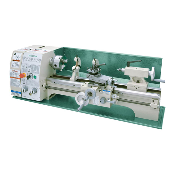
10" X 22" BENCHTOP LATHE
OWNER'S MANUAL
(For models manufactured since 11/12)
G0602 Shown
COPYRIGHT © MARCH, 2013 BY GRIZZLY INDUSTRIAL, INC. REVISED MARCH, 2014 (BL)
WARNING: NO PORTION OF THIS MANUAL MAY BE REPRODUCED IN ANY SHAPE
OR FORM WITHOUT THE WRITTEN APPROVAL OF GRIZZLY INDUSTRIAL, INC.
#BL15556 PRINTED IN CHINA
Advertisement
Table of Contents

Related Manuals for Grizzly G0602


Summary of Contents for Grizzly G0602
- Page 1 (For models manufactured since 11/12) G0602 Shown COPYRIGHT © MARCH, 2013 BY GRIZZLY INDUSTRIAL, INC. REVISED MARCH, 2014 (BL) WARNING: NO PORTION OF THIS MANUAL MAY BE REPRODUCED IN ANY SHAPE OR FORM WITHOUT THE WRITTEN APPROVAL OF GRIZZLY INDUSTRIAL, INC.
- Page 2 This manual provides critical safety instructions on the proper setup, operation, maintenance, and service of this machine/tool. Save this document, refer to it often, and use it to instruct other operators. Failure to read, understand and follow the instructions in this manual may result in fire or serious personal injury—including amputation, electrocution, or death.
-
Page 3: Table Of Contents
Chuck Removal..........28 Controls & Components ......... 6 Changing Jaw Set ........28 Scroll Chuck Clamping ........ 29 Model G0602 Control Panel ....... 6 4-Jaw Chuck ..........30 Model G0752 Control Panel ....... 6 Faceplate ............. 31 Quick Change Gearbox ........6 Tailstock ............ - Page 4 Bed & Leadscrew ......... 79 Change Gears ........... 55 Machine Storage .......... 56 Steady Rest & Follow Rest ......80 G0602 Motor & Electrical ......81 SECTION 7: SERVICE ........57 G0752 Motor & Electrical ......82 Troubleshooting ........... 57 Change Gears..........
-
Page 5: Introduction
Models G0602 and G0752 both require setting for an updated version. We post current manuals gearbox dial positions and positioning V-belts to and manual updates for free on our website at select the spindle speed. -
Page 6: Model G0602 Identification
DO NOT machine. Do not operate this machine until connect power until instructed to do so you have understood this entire manual later in this manual. and received proper training. Model G0602/G0752 (Mfg. Since 11/12) -
Page 7: Model G0752 Identification
DO NOT machine. Do not operate this machine until connect power until instructed to do so you have understood this entire manual later in this manual. and received proper training. Model G0602/G0752 (Mfg. Since 11/12) -
Page 8: Controls & Components
Quick Change Gearbox Model G0602 Control Panel Figure 5. Gearbox dials. Figure 3. Model G0602 control panel. G. Numeric Gearbox Dial: Controls the leadscrew for threading and feeding opera- Model G0752 Control Panel tions. To make a selection, rotate the dial to the corresponding number displayed on the threading or feed charts. -
Page 9: Carriage
M. Half Nut Lever: Engages/disengages half V-Belt: Transfers power from the motor pul- nut for power feed and threading operations. ley to the spindle pulley. Model G0602 uses two V-belts. Model G0752 uses one V-belt. N. Thread Chart: Indicates which thread dial mark to use when engaging the half nut for Z. -
Page 10: Machine Data Sheet
Operation Information Swing Over Bed ⁄ " Distance Between Centers 22 in. Swing Over Cross Slide ⁄ Swing Over Saddle ⁄ Maximum Tool Bit Size ⁄ Compound Travel ⁄ Carriage Travel ⁄ Cross Slide Travel ⁄ Model G0602/G0752 (Mfg. Since 11/12) - Page 11 Headstock Gears Steel Hardened and Precision-Ground Cast Iron Stand Cast Iron Paint Epoxy Other Country of Origin China Warranty 1 Year Serial Number Location ID Label on Headstock Approximate Assembly & Setup 1 Hour Time Model G0602/G0752 (Mfg. Since 11/12)
-
Page 12: Section 1: Safety
Everyday ery. Never operate under the influence of drugs or eyeglasses are NOT approved safety glasses. alcohol, when tired, or when distracted. -10- Model G0602/G0752 (Mfg. Since 11/12) - Page 13 Contact our debris. Make sure they are properly installed, Technical Support at (570) 546-9663. undamaged, and working correctly. -11- Model G0602/G0752 (Mfg. Since 11/12)
-
Page 14: Additional Safety For Metal Lathes
Make sure no part of the tool, tool holder, com- pound rest, cross slide, or carriage will contact the chuck during operation. -12- Model G0602/G0752 (Mfg. Since 11/12) -
Page 15: Glossary Of Terms
Gib: A tapered wedge located along a sliding member to take up wear or to ensure a proper fit. Headstock: The major lathe component that houses the spindle and motor drive system to turn the workpiece. -13- Model G0602/G0752 (Mfg. Since 11/12) -
Page 16: Section 2: Power Supply
Phase ........... Single-Phase electrical wiring must be done by an electrican or Minimum Circuit Size (G0602) ..20 Amps qualified service personnel in accordance with all Minimum Circuit Size (G0752) ..15 Amps applicable codes and standards. -
Page 17: Grounding & Plug Requirements
Two-prong outlets do not meet the grounding requirements for this machine. Do not modify or use an adapter on the plug provided—if it will not fit the outlet, have a qualified electrician install the proper outlet with a verified ground. -15- Model G0602/G0752 (Mfg. Since 11/12) -
Page 18: Section 3: Setup
Forklift/Power Lifting Device (rated for at least 500 lbs.) ............1 • Bench Mounting Hardware ..As Needed SUFFOCATION HAZARD! Keep children and pets away from plastic bags or packing materials shipped with this machine. Discard immediately. -16- Model G0602/G0752 (Mfg. Since 11/12) -
Page 19: Inventory
L. Low Range Belt 27 ⁄ " (G0602) ....1 fully check around/inside the machine and High Range Belt 33" (Installed, G0602) ..1 packaging materials. Often, these items get V-Belt 33" (Installed, G0752) ...... 1 lost in packaging materials while unpack- M. -
Page 20: Cleanup
Repeat Steps 2–3 as necessary until clean, Figure 12. T23692 Orange Power Degreaser. then coat all unpainted surfaces with a quality metal protectant to prevent rust. -18- Model G0602/G0752 (Mfg. Since 11/12) -
Page 21: Site Considerations
Wall Min. 30" for Maintenance 65" 110V Supply 18" Access Lathe Door 30" Keep 12.5" Workpiece Footprint Loading Area Unobstructed 47.5" Footprint Figure 13. Minimum working clearances. -19- Model G0602/G0752 (Mfg. Since 11/12) -
Page 22: Lifting & Placing
Note: Before attempting to move the car- riage, make sure the carriage lock is loose and the half nut is disengaged. -20- Model G0602/G0752 (Mfg. Since 11/12) -
Page 23: Leveling & Mounting
See the figure below for an example of a high Flat Washer precision level. Lathe Silicon Chip Pan Workbench Flat Washer Hex Bolt Figure 16. Example of a through mount setup. Figure 15. Grizzly Model H2683 12" Master Machinist's Level. -21- Model G0602/G0752 (Mfg. Since 11/12) -
Page 24: Assembly
Damage caused to the bearings and gears from running the lathe without oil in the reservoirs will not be covered under warranty. Refer to the Lubrication section, beginning on Page 52, for details on how to lubricate the lathe. -22- Model G0602/G0752 (Mfg. Since 11/12) - Page 25 Make sure chuck and jaws, if installed, are secure (see Chuck Installation on Page 27). G0602: Push the green ON button, then turn the spindle direction switch to FWD. The Note: If a chuck is not installed on the lathe, spindle should be rotating counterclockwise—...
-
Page 26: Spindle Break-In
Backlash adjustment (Page 60) To perform the spindle break-in: Operate the lathe at 150 RPM for 10 minutes. G0602: Repeat Step 1 at each of the following speeds 300, 560, 720, 1200, and 2400. G0752: Repeat Step 1 at each of the following approximate speeds: 800, 1300, and 2000. -
Page 27: Section 4: Operations
Regardless of the content in this sec- tion, Grizzly Industrial will not be held liable for accidents caused by lack of training. Complete the Test Run & Break-In proce- dure on Pages 22– 24 before using this lathe for any cutting or threading operations;... -
Page 28: Chuck & Faceplate Mounting
Figure 20. Examples of common devices used LARGE, VERY HEAVY CHUCKS concentric workpieces, straight turning between during chuck installation and removal. Pre-Threaded Hole Fabricated Steel centers, off-center turning, and boring. for Lifting Eye Lifting Hook -26- Model G0602/G0752 (Mfg. Since 11/12) -
Page 29: Chuck Installation
Chuck Lock Thoroughly clean, inspect, deburr, and lightly Figure 23. Chuck lock installed on spindle nose oil all threads and mating surfaces. and chuck. Thread the chuck onto the spindle nose and hand-tighten it. -27- Model G0602/G0752 (Mfg. Since 11/12) -
Page 30: Chuck Removal
Guides Jaw Numbers Insert Keys Here Figure 25. Location to insert chuck keys when removing chuck. Figure 27. Jaw guide and jaw numbers. Support the chuck, unscrew it, and remove. -28- Model G0602/G0752 (Mfg. Since 11/12) -
Page 31: Scroll Chuck Clamping
Re-install the jaws sequentially 1–3, Poor Scroll and make sure each one engages with the CORRECT Gear Engagement INCORRECT scroll-gear lead thread during its first rota- Figure 29. Jaw selection and workpiece holding. tion. -29- Model G0602/G0752 (Mfg. Since 11/12) -
Page 32: 4-Jaw Chuck
With help from another person or a holding device, position the workpiece so it is cen- tered in the chuck. Figure 31. Generic picture of non-cylindrical workpiece correctly mounted on the 4-jaw chuck. -30- Model G0602/G0752 (Mfg. Since 11/12) -
Page 33: Faceplate
Faceplate the operator or bystanders. Use a minimum of THREE independent clamping devices to Figure 32. Generic picture of workpiece clamped hold the workpiece onto the faceplate. in a faceplate. -31- Model G0602/G0752 (Mfg. Since 11/12) -
Page 34: Tailstock
Otherwise, removal of such tooling may be difficult. Turn the quill handwheel clockwise to move the quill toward the spindle or counterclock- wise to move it away from it. Tighten the quill lock lever. -32- Model G0602/G0752 (Mfg. Since 11/12) -
Page 35: Removing Tooling
Note: The marks on the offset indicator are arbi- offset. trary. For a precise offset, use a dial indicator to check quill movement while adjusting the screws. Tools Needed Hex Wrench 4mm ..........1 Open-End Wrench 19mm ........1 -33- Model G0602/G0752 (Mfg. Since 11/12) -
Page 36: Aligning Tailstock To Spindle Centerline
Note: If necessary in the following step, a dead center, and turn it to a 60° point, as refer to Offsetting Tailstock on Page 33 for illustrated in Figure 38. detailed instructions. Figure 38. Turning a dead center. -34- Model G0602/G0752 (Mfg. Since 11/12) - Page 37 Figure 41. Adjust tailstock away from the Looking down from above operator. Repeat Steps 6–8 until the desired accuracy Figure 40. Adjust tailstock toward the operator. is achieved. -35- Model G0602/G0752 (Mfg. Since 11/12)
-
Page 38: Centers
Use the dead center in the spindle for operations where the workpiece rotates with the center and Figure 43. Example photo of using a dead does not generate friction. center with a faceplate and lathe dog. -36- Model G0602/G0752 (Mfg. Since 11/12) -
Page 39: Removing Center From Spindle
To remove the center from the quill, hold onto it on the tapers. with a gloved hand or shop rag, then rotate the quill handwheel counterclockwise to draw the quill back into the casting until the center releases. -37- Model G0602/G0752 (Mfg. Since 11/12) -
Page 40: Mounting Workpiece Between Centers
Secure the quill lock lever and tailstock lock gers are barely touching the workpiece, then nut. tighten the finger lock nuts. Lubricate the finger tips with an anti-seize lubricant during operation. Note: Mill or file the tips if they show wear. -38- Model G0602/G0752 (Mfg. Since 11/12) -
Page 41: Follow Rest
Carriage ence point. This will allow you to quickly Lock Lock return the compound rest to that exact angle the next time you need to cut threads. Figure 48. Carriage and cross slide locks. -39- Model G0602/G0752 (Mfg. Since 11/12) -
Page 42: Four-Way Tool Post
Page 34 for detailed instructions). Firmly secure the cutting tool with at least two tool post screws. Check and adjust the cutting tool to the spindle centerline, as instructed in the next subsection. -40- Model G0602/G0752 (Mfg. Since 11/12) -
Page 43: Manual Feed
Set the compound rest angle by hand-rotating it and securing in place with two hex nuts. The com- pound rest has an indirect-read graduated dial. -41- Model G0602/G0752 (Mfg. Since 11/12) -
Page 44: Spindle Speed
Spindle Speed Setting Spindle Speed Selecting one of the available six spindle speeds (Model G0602) or one of the three spindle speed ranges (Model G0752) is performed by reposition- Using the correct spindle speed is important for ing the V-belt(s) between the pulleys. -
Page 45: G0752 Configuration Example
Figure 56. Positioning belt for high speed. Follow along with the examples below for setting Figure 58. Location of tensioner lock nut. the Model G0602 spindle speed to gain a better understanding of this task. Move the tensioner to install the 27 ⁄... -
Page 46: Power Feed
To learn how to power the carriage for threading operations, refer to Threading on Page 46. Tools Needed Hex Wrench 5mm ..........1 Hex Wrench 6mm ..........1 -44- Model G0602/G0752 (Mfg. Since 11/12) -
Page 47: Setting Power Feed Rate
E-clips and cap screw. after completing power feeding operations. Feed Chart Change Gears E-Clips = 0.012" Feed Screw Lash Adjuster Cap Screw Feed Dials Figure 61. Power feed setup. -45- Model G0602/G0752 (Mfg. Since 11/12) -
Page 48: Threading
Gather the required change gears based upon the chart. Inch Thread Chart E-Clips = 64 TPI Screw Lash Adjuster Figure 62. Threading setup for 64 TPI. -46- Model G0602/G0752 (Mfg. Since 11/12) -
Page 49: Apron Threading Controls
Instead you must leave the half nut nut when required and prevent an apron engaged from the beginning until the threading crash! operation is complete. -47- Model G0602/G0752 (Mfg. Since 11/12) - Page 50 1 or 7 on the thread dial (see Figure 67). POSITION POSITION Figure 67. 9 ⁄ , 11 ⁄ ⁄ TPIs. POSITION All Other TPI 1,4, 7, 10 POSITION All Other TPI 1,4, 7, 10 -48- Model G0602/G0752 (Mfg. Since 11/12)
-
Page 51: Section 5: Accessories
Run a Lathe book. H2987—½" Bent Lathe Dog H2988—1" Bent Lathe Dog H2989—1½" Bent Lathe Dog H2990—2" Bent Lathe Dog H2991—3" Bent Lathe Dog Figure 72. G9849 Magnetic Base/Dial Indicator. -49- Model G0602/G0752 (Mfg. Since 11/12) - Page 52 Figure 76. ISO 68 and ISO 32 machine oil. H5930—4-Pc Center Drill Set 60° H5931—4-Pc Center Drill Set 82° Double ended HSS Center Drills are precision ground. Includes sizes 1-4. www.grizzly.com 1-800-523-4777 order online at or call -50- Model G0602/G0752 (Mfg. Since 11/12)
-
Page 53: Section 6: Maintenance
(especially parts • Ensure carriage lock bolt is loose. that are exposed to water soluble cutting fluid). Use a quality rust protectorate such as SLIPIT ® Boeshield to prevent corrosion. ® -51- Model G0602/G0752 (Mfg. Since 11/12) -
Page 54: Lubrication
Re-install the drain plug. -52- Model G0602/G0752 (Mfg. Since 11/12) -
Page 55: Ball Oilers
Refer to Figures 79–83 to identify the location of each ball oiler. Ball Oiler Ball Oilers Figure 82. Tailstock ball oiler. Ball Oiler Figure 79. Spindle bearing ball oilers. Figure 83. Leadscrew end bearing ball oilers. -53- Model G0602/G0752 (Mfg. Since 11/12) -
Page 56: Leadscrew & Carriage Rack
Before lubricating the bedways (see Figure 84), clean it with mineral spirits. Apply a thin coat of oil along the length of the bedway. Move the steady rest, carriage, and tailstock to access the entire length of the bedways. -54- Model G0602/G0752 (Mfg. Since 11/12) -
Page 57: Change Gears
Make sure the change gear cover remains installed whenever possible to keep the gears free of dust or debris from the outside environment. -55- Model G0602/G0752 (Mfg. Since 11/12) -
Page 58: Machine Storage
Lubricate the machine as outlined in the Lubrication section beginning on Page 52. Be sure to use an oil can to purge all ball oil- ers and oil passages with fresh oil. -56- Model G0602/G0752 (Mfg. Since 11/12) -
Page 59: Section 7: Service
2. Refer to the feeds and speed charts in Machinery's Handbook or a speeds and feeds calculator on the down under load. cutting operation. internet. 3. Cutting tool is dull. 3. Sharpen or replace the cutting tool. -57- Model G0602/G0752 (Mfg. Since 11/12) -
Page 60: Operation
3. Adjust gibs at affected component (see Page 61). cutting. 4. Dull cutting tool. 4. Replace or resharpen cutting tool. 5. Incorrect spindle speed or feed rate. 5. Use the recommended spindle speed and feed rate. -58- Model G0602/G0752 (Mfg. Since 11/12) - Page 61 7. Gears or shear pin broken. Quick-change gear 1. Gears not aligned inside headstock/quick 1. Rotate spindle by hand with light pressure on the change dials will not change gearbox. dial until gear falls into place. shift into position. -59- Model G0602/G0752 (Mfg. Since 11/12)
-
Page 62: Backlash Adjustment
0.002"–0.003", as indicated on the graduated dial. Tighten the set screw to secure the setting. -60- Model G0602/G0752 (Mfg. Since 11/12) -
Page 63: Gib Adjustment
Cross Slide Re-check the movement of the slide and, if Adjustment necessary, repeat Steps 2–4. Fasteners Figure 89. Cross slide gib adjustment hex nuts and set screws. -61- Model G0602/G0752 (Mfg. Since 11/12) -
Page 64: Half Nut Adjustment
While keeping the set screws from moving, shear pin completely through the holes in the re-tighten the hex nuts, then re-install the collar and leadscrew. thread dial. -62- Model G0602/G0752 (Mfg. Since 11/12) -
Page 65: V-Belt Tension & Replacement
Replace the V-belts if they Tensioner become cracked, frayed, or glazed. On the Model G0602, the low range V-belt ten- Figure 94. Model G0752 tensioner and lock bolt. sion is controlled by a tensioner between the secondary drive pulley (B) and spindle (C) pulley. -
Page 66: Replacing V-Belt
To tension the Model G0602 high range —If the low range belt between pulleys B and V-belt: C (see Figure 97) needs to be replaced, loosen the tensioner lock nut (see Figure Follow Steps 1–3 in "Tensioning Timing Belt" 93 on Page 63), move the tensioner down, on Page 65. -
Page 67: Timing Belt Tension & Replacement
Timing Belt Tension & Replacement Pulley Deflection On the Model G0602 the timing belt transfers ⁄ " power from the motor to the secondary drive pul- ley (see Figure 99). If the timing belt becomes excessively worn or damaged, you will need to Pulley replace it. -
Page 68: Section 8: Wiring
Technical source. Support at (570) 546-9663. The photos and diagrams included in this section are best viewed in color. You can view these pages in color at www.grizzly.com. -66- Model G0602/G0752 (Mfg. Since 11/12) -
Page 69: G0602 Wiring Diagram
Rear CANSEN LW26-20 Button View Switch Switch Rotary Switch Wiring Box Control Panel (Shown from behind) Motor 1HP 110V Neutral 110 VAC 5-15 Plug (As Recommended) Ground Ground READ ELECTRICAL SAFETY -67- Model G0602/G0752 (Mfg. Since 11/12) ON PAGE 66! -
Page 70: G0602 Electrical Components
Figure 101. Spindle direction switch and ON Figure 104. Spindle direction switch and button. emergency stop switch. Figure 102. Electrical box. Figure 105. Magnetic contactor. Figure 103. Motor connection detail. READ ELECTRICAL SAFETY -68- Model G0602/G0752 (Mfg. Since 11/12) ON PAGE 66! -
Page 71: G0752 Wiring Box Diagram
L1 N1 Transformer BEIJING AOHENGDA ELECTRICAL JBK5-40VA Wiring Box To Power To Left Motor To Right Motor Supply Junction Box Junction Box Page 73 Page 73 Page 73 READ ELECTRICAL SAFETY -69- Model G0602/G0752 (Mfg. Since 11/12) ON PAGE 66! -
Page 72: G0752 Wiring Box Components
G0752 Wiring Box Components Figure 106. G0752 electrical box. READ ELECTRICAL SAFETY -70- Model G0602/G0752 (Mfg. Since 11/12) ON PAGE 66! -
Page 73: G0752 Control Panel Wiring Diagram
3 NO Ground LA252HBE102C LA252HBE102C LA252HBE101C Spindle OFF Button ON Button E-Stop Direction Switch Switch Button Switch Switch Control Panel (Viewed from Behind) See Figure 107, on Page 72 READ ELECTRICAL SAFETY -71- Model G0602/G0752 (Mfg. Since 11/12) ON PAGE 66! -
Page 74: G0752 Control Panel Components
Figure 107. Control panel. Figure 108. RPM display. Figure 111. Right junction box. Figure 109. Variable speed potentiometer. Figure 112. Spindle speed sensor. Figure 110. Spindle speed circuit board. READ ELECTRICAL SAFETY -72- Model G0602/G0752 (Mfg. Since 11/12) ON PAGE 66! -
Page 75: G0752 Motor Wiring Diagram
110V 30W 1PH 5-15 Plug (As Recommended) Neutral Ground Ground To Wiring To Wiring To Wiring Page 69 Page 69 Page 69 Figure 113. Left motor junction box. Figure 114. Right motor junction box. -73- Model G0602/G0752 (Mfg. Since 11/12) -
Page 76: Section 9: Parts
SECTION 9: PARTS Spindle & Drive Belt 54-3 54-4 19-1 (G0752) 54-2 (G0602) 54-1 55-2 (G0752) (G0602) (G0602) LEFT REAR VIEW (G0602) 55-3 (G0752) 55-1 -74- Model G0602/G0752 (Mfg. Since 11/12) - Page 77 KEY 6 X 6 X 40 PCAP06M CAP SCREW M6-1 X 25 P0602039 SPACER PW03M FLAT WASHER 6MM P0602040 STANDOFF STUD M10-1.5 X 50, 15, 25 (G0602) P0602007 COMPRESSION SPRING PB56M CAP SCREW M10-1.5 X 20 (G0752) P0602008 CLAMP P0602041...
-
Page 78: Apron
P0602110 DOWEL PIN 4 X 16 P0752133 CARRIAGE HANDWHEEL (G0752) PSS34M SET SCREW M5-.8 X 16 PRP04M ROLL PIN 4 X 24 (G0602) PSS12M SET SCREW M6-1 X 25 PSS04M SET SCREW M6-1 X 12 (G0752) PN06M HEX NUT M5-.8... -
Page 79: Tool Post & Compound Rest
PK03M KEY 3 X 3 X 8 PCAP26M CAP SCREW M6-1 X 12 P0602229 POINTER PSS34M SET SCREW M5-.8 X 16 P0602230 THREADED COLLAR PN06M HEX NUT M5-.8 PSS17M SET SCREW M8-1.25 X 6 -77- Model G0602/G0752 (Mfg. Since 11/12) -
Page 80: Tailstock
GRADUATED DIAL PB158M HEX BOLT M12-1.75 X 90 P0602310 TAILSTOCK HANDWHEEL POINTER PW06M FLAT WASHER 12MM P0602311 HANDWHEEL BUSHING PSS26M SET SCREW M5-.8 X 6 P0602312 TAILSTOCK BODY P0602326 LOWER OFFSET PLATE P0602313 TAILSTOCK BASE -78- Model G0602/G0752 (Mfg. Since 11/12) -
Page 81: Bed & Leadscrew
SET SCREW M8-1.25 X 40 P0602405 LEADSCREW END BRACKET PW01M FLAT WASHER 8MM P0602406 BALL OILER 6MM PN03M HEX NUT M8-1.25 PCAP02M CAP SCREW M6-1 X 20 P0602415 CHIP PAN PLN05M LOCK NUT M10-1.5 -79- Model G0602/G0752 (Mfg. Since 11/12) -
Page 82: Steady Rest & Follow Rest
P0602506 ADJUSTING SCREW PN01M HEX NUT M6-1 P0602507 CLAMPING PLATE PLW03M LOCK WASHER 6MM PB125M HEX BOLT M12-1.75 X 65 PCAP40M CAP SCREW M8-1.25 X 35 PW06M FLAT WASHER 12MM PW01M FLAT WASHER 8MM -80- Model G0602/G0752 (Mfg. Since 11/12) -
Page 83: G0602 Motor & Electrical
611V2-1 P0602611V2-1 MOTOR FAN P0602619 ON PUSH BUTTON MINGER LA125H-BE101C 611V2-2 P0602611V2-2 MOTOR FAN COVER P0602620 ROTARY SWITCH CANSEN LW26-20 M09T/3 611V2-3 PC150 S CAPACITOR 150M 125V P0602621 G0602 CONTROL PANEL 611V2-4 P0602611V2-4 R CAPACITOR 20M 400V -81- Model G0602/G0752 (Mfg. Since 11/12) -
Page 84: G0752 Motor & Electrical
611-6 P0602611-6 POWER CORD 16G 3W 60" 5-15P P0752631 FUSE 2A 250V PW05M FLAT WASHER 4MM P0752632 FUSE HOLDER P0602617 CONTACTOR SIEMENS 3TB41 22E 110V P0752633 TERMINAL POST MOUNTING BRACKET P0752618 TRANSFORMER BAEEC JBK5-40VA P0752634 GROUNDING BAR -82- Model G0602/G0752 (Mfg. Since 11/12) -
Page 85: Change Gears
GEAR SHAFT CLIP P0602737 GEAR 60T P0602708 BALL OILER 6MM P0602703 GEAR 60T PLASTIC P0602720 BUSHING P0602739 GEAR 104T PK97M KEY 4 X 4 X 14 P0602740 GEAR 120T P0602722 SPACER RING P0602741 GEAR 127T -83- Model G0602/G0752 (Mfg. Since 11/12) -
Page 86: Gearbox
Gearbox 846 847 -84- Model G0602/G0752 (Mfg. Since 11/12) - Page 87 O-RING 1.8 X 6.7 PR05M EXT RETAINING RING 15MM P0602847 SHAFT PK65M KEY 4 X 4 X 8 PRP03M ROLL PIN 5 X 20 P0602824 GEAR SHAFT 22T P0602849 SHIFT LEVER P0602825 GEAR 44T P0602850 SHIFT FORK -85- Model G0602/G0752 (Mfg. Since 11/12)
-
Page 88: Cross Slide & Carriage
BALL OILER 6MM P0602917 SLIDE BLOCK PCAP40M CAP SCREW M8-1.25 X 35 P0602918 CHIP GUARD PCAP48M CAP SCREW M6-1 X 35 PCAP26M CAP SCREW M6-1 X 12 P0602939 HANDLE SCREW PSS11M SET SCREW M6-1 X 16 -86- Model G0602/G0752 (Mfg. Since 11/12) - Page 89 P0602947 DISCONNECT POWER LABEL ALUM P0602855 READ MANUAL LABEL ALUMINUM P0602948 CARRIAGE FEED DAMAGE LABEL ALUM P0602940 MACHINE ID LABEL ALUMINUM PPAINT-1 GRIZZLY TOUCH-UP PAINT P0602941 ENTANGLEMENT LABEL ALUMINUM PPAINT-11 PUTTY TOUCH-UP PAINT P0602946 SHIFT NOTICE LABEL ALUMINUM -87- Model G0602/G0752 (Mfg. Since 11/12)
- Page 90 PLABEL-55A ENTANGLEMENT LABEL PPAINT-11 PUTTY TOUCH-UP PAINT FOR GRIZZLY MACHINES ONLY! DO NOT REPRODUCE OR CHANGE THIS ARTWORK PLABEL-62C DISCONNECT POWER LABEL PPAINT-1 GRIZZLY GREEN TOUCH-UP PAINT WITHOUT WRITTEN APPROVAL! manuals@grizzly.com P0752068 ENTANTANGLEMENT-GEARS LABEL -88- Model G0602/G0752 (Mfg. Since 11/12)
-
Page 91: Section 10: Appendix
SECTION 10: APPENDIX machine G0602 Charts -89- Model G0602/G0752 (Mfg. Since 11/12) -
Page 92: G0752 Charts
G0752 Charts... -
Page 93: Warranty Card
Do you think your machine represents a good value? _____ Yes _____No Would you recommend Grizzly Industrial to a friend? _____ Yes _____No Would you allow us to use your name as a reference for Grizzly customers in your area? Note: We never use names more than 3 times. - Page 94 FOLD ALONG DOTTED LINE Place Stamp Here GRIZZLY INDUSTRIAL, INC. P.O. BOX 2069 BELLINGHAM, WA 98227-2069 FOLD ALONG DOTTED LINE Send a Grizzly Catalog to a friend: Name_______________________________ Street_______________________________ City______________State______Zip______ TAPE ALONG EDGES--PLEASE DO NOT STAPLE...
-
Page 95: Warranty And Returns
WARRANTY AND RETURNS Grizzly Industrial, Inc. warrants every product it sells for a period of 1 year to the original purchaser from the date of purchase. This warranty does not apply to defects due directly or indirectly to misuse, abuse, negligence, accidents, repairs or alterations or lack of maintenance.