Table of Contents
Advertisement
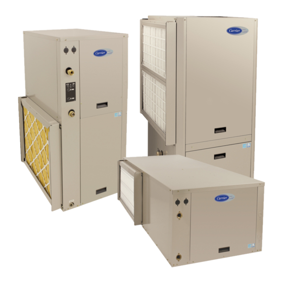
GC Series
Geothermal Heat Pump
Sizes 024, 036, 048, 060, 072
NOTE: Read the entire instruction manual before starting the installation.
. . . . . . . . . . . . . . . . . . . . . . . . . . . . . . .
. . . . . . . . . . . . . . . . . . . . . . . . . . .
. . . . . . . . . . . . . . . . . . . . . . . . . . . .
. . . . . . . . . . . . . . . . . . . . . . . . . . .
. . . . . . . . . . . . . . . . . . . . . . . . . . . . . . . . .
. . . . . . . . . . . . . . . . . . . . . . . . . . . . . . . . . . . .
. . . . . . . . . . . . . . . . . . . . . . . . . . . . . . . . . . . . . . . .
. . . . . . . . . . . . . . . . . . . . . . . . .
. . . . . . . . . . . . . . . . . . . . . . . . . .
. . . . . . . . . . . . . . . . . . . . . . . . . . .
. . . . . . . . . . . . . . . . . . . . . . . . . . . . .
. . . . . . . . . . . . . . . . . . . . . . . . . . . . . . . . .
. . . . . . . . . . . . . . . . . . . . . . . . .
. . . . . . . . . . . . . . . . . . . . . . . . . .
. . . . . . . . . . . . . . . . . . . . . . . . . . . . .
. . . . . . . . . . . . . . . . . . . . . . . . . . . . . .
. . . . . . . . . . . . . . . . . . . . . . . . . . . . . . . . . .
. . . . . . . . . . . . . . . . . . . . . . . . .
Installation Instructions
TABLE OF CONTENTS
PAGE NO.
. . . . . . . . . . . . . . . . . . . . .
. . . . . . . . . . . . . . .
. . . . . . . . . . .
. . . . . . . . . . . . . . . . . . .
. . . . . . . . . . . . . . . .
. . . . . . . . . . . .
. . . . . . . . . . . . . . . . . . . . . . . .
. . . . . . . . . . . . . . . . . . . . . .
. . . . . . . . . . . . . . . .
. . . . . . . . . . . . . . . . . .
. . . . . . . .
. . .
. . . . .
. . . . . . . . . . . . . .
. . . . . . . . . . . . . . . .
. . . . . . . . . . . . . . . . . . . . . . .
. . . . . . . . . . . . . .
. . . . . . . . . . . . . . . . . . . . . . .
. . . . . . . . . . . . . . . . . .
. . . . . . . . . . . . . . . . . . .
. . . . . . . . . . . . . . . . .
2
2
3
3
4
6
6
6
7
7
7
7
8
8
8
8
9
12
12
12
12
14
14
14
14
15
15
15
16
16
16
17
17
17
17
17
17
17
18
. . . . . . . . . . . . . . . . . . .
. . . . . . . . . . . . . .
. . . . . . . . . . . . . . . . . . . . . . .
. . . . . . . . . . . . . . . . . . . . . .
. . . . . . . . . . . . . . . . . . . . . . . . . . . . . . . . .
. . . . . . . . . . . . . . . . . . . .
. . . . . . . . . . . . . . . . . . . . . . . . . . . . . . . . .
. . . . . . . . . . . . . . . . . . . .
. . . . . . . . . . . . . . . . . .
. . . . . . . . . .
. . . . . . . . . . . . .
. . . . . . . . . . . . . . . . . . . . . . . . . . . . . . . .
. . . . . . . . . . . . . . . . . . . . . . . .
. . . . . . . . . . . . . . . . . . . . . . . . .
. . . . . . . . . . . . . . . . . . . . .
. . . . . . . . . . . . . . . . . . . . . .
. . . . . . . . . . . . . . . . .
. . . . . . . . . . . . . . . . . . . .
. . . . . . . . . . . . . . . . . . . . . . . . . .
. . . . . . . . . . . . . . . . . . . . . . . .
. . . . . . . . . . .
. . . . . . . . . . .
. . . . . . . . . . .
. . . . . . . . . . . . . . .
. . . . . . . . . . . . . . .
. . . . . . . . . . .
. . . . . . . . . . . . . . . . . . . . . . . . . . . . .
. . . . . . . . . . . . . . . . . . . . . . . . . . . .
. . . . . . . . . . . . . . . . . . . . . . . . . . . .
. . . . . . . . . . . . . . . . . . . . . . . . . . . . . . .
PAGE NO.
18
18
. .
18
19
19
19
22
23
23
. . .
25
24
. . . . . . . . .
30
30
. . . . . . . .
31
32
. . . . .
33
. . . . . . .
33
33
33
33
33
33
. . . . . . . .
33
33
33
34
34
36
35
. . . . . . . .
36
36
36
36
36
. . . . . . .
39
39
39
. . . . . . . . .
40
41
45
Advertisement
Table of Contents
Troubleshooting

Related Manuals for Carrier GC Series


Summary of Contents for Carrier GC Series
-
Page 1: Table Of Contents
GC Series Geothermal Heat Pump Sizes 024, 036, 048, 060, 072 Installation Instructions NOTE: Read the entire instruction manual before starting the installation. TABLE OF CONTENTS PAGE NO. PAGE NO. SAFETY CONSIDERATIONS PRE START- -UP CHECKLIST ..... -
Page 2: Safety Considerations
Fig. 1 - - Standard Package refrigerant compressors. Pressurized mixtures of air or gases containing 1. GC Series Water- -To Air Heat Pump oxygen can lead to an explosion. 2. Installation and Owner’s Manual 3. Hanging Bracket Kit (HZ unit only) -
Page 3: Application Considerations
APPLICATION CONSIDERATIONS Geothermal Systems Closed loop and pond applications require specialized design knowledge. No attempt at these installations should be made unless the dealer has received specialized training. It is recommend that design and installation of the ground loop be per International Ground Source Heat Pump Assoc. -
Page 4: Well Water Systems
Well Water Systems IMPORTANT: Table 1 must be consulted for water quality Proper testing is required to assure the well water quality is suitable for use with water source equipment. requirements when using open loop systems. A water sample must be obtained and tested, with the results compared to the table. - Page 5 Table 1 – Water Quality Requirements for Open- -Loop Geothermal Heat Pump System ACCEPTABLE VALUE POTENTIAL PROBLEM WATER CHARACTERISTIC COPPER CUPRO---NICKEL pH (Acidity / Alkalinity) 7--- 9 7--- 9 SCALING Hardness (CaCO3, MgCO3) < 350 ppm < 350 ppm Ryznar Stability Index 6.0 --- 7.5 6.0 --- 7.5 Langelier Saturation Index...
-
Page 6: Installation Recommendations
The manufacturer recommends these be must be reported to the carrier within 24 hours of receipt. attached to the unit corners by hanger bracket kits. The rods must Location / Clearance be securely anchored to the ceiling. -
Page 7: Condensate Drain
CONDENSATE DRAIN If the duct system is too small, larger duct work should be installed. Check for existing leaks and repair. IMPORTANT: This connection must be in conformance with The duct system and all diffusers should be sized to handle the local plumbing codes. -
Page 8: Piping & Plumbing Installation
Always check carefully for water leaks and repair appropriately. Water Solenoid Valves Units are equipped with female pipe thread fittings. Consult Unit Open loop well water applications require a water solenoid valve. Dimensional Drawings. The purpose of the valve is to allow water to flow through the NOTE: Teflon tape sealer should be used when connecting water GHP only during operation. -
Page 9: Typical Open Loop Piping
Typical Open Loop Piping Open loop systems require a water solenoid valve to turn on the temperature pressure drop start- -up during water when the heat pump compressor is energized, and to turn off troubleshooting. the water when the compressor is off. Fig. - Page 10 Water Solenoid Valve Wiring Diagrams for Open Loop Systems 24 VAC Controls THERMOSTAT HE AT P UMP THERMOSTAT HE AT P UMP J umper J umper E ND SWIT C H MVBR3F or MVBR4F E ND SWIT C H MVBR3F or MVBR4F E ND SWIT C H MVBR3F or MVBR4F...
- Page 11 From PL5 ext. harness From PL5 ext. harness IMPORTANT: Ensure that wire colors match up harness (brown E ND E ND to brown, blue SWIT C H SWIT C H to blue, black to MVBR3F or MVBR4F MVBR3F or MVBR4F black.
-
Page 12: Utility Curtailment
FACTORY INSTALLED OPTIONS Utility Curtailment Utility curtailment is a voluntary energy saving program offered A number of factory installed options are available on the GC through utility companies in some locations. Utility company will Series of Heat Pumps. The following details the purpose, function provide the equipment that allows them to cut back demand on and components of each option. - Page 13 Water Tank Preparation Water Tank Refill 1. Turn off electrical or fuel supply to the water heater. 1. Open the cold water supply to the tank. 2. Attach garden hose to water tank drain connection and run 2. Open a hot water faucet to vent air from the system until other end of hose out doors or to an open drain.
-
Page 14: Electrical
ELECTRICAL Electrical Connections Low- -Voltage Circuit Fusing and Reference The low- -voltage circuit is fused by a board- -mounted 3- -amp. WARNING automotive fuse placed in series with transformer SEC1 and R circuit. The C circuit of transformer circuit is referenced to chassis ground through a printed circuit run at SEC2 and metal PC board ELECTRICAL OPERATION HAZARD mounting eyelets. -
Page 15: Electronic Thermostat Installation
Table 5 – Recommended Thermostats CIRCUIT BOARD Carrier Systems: Bryant Systems: Infinityr Touch Evolutionr Connex™ Wall Control Wall Control BOARD SYSTXCCITC01* SYSTXBBECC01* SYSTXCCITW01* SYSTXBBECW01* SYSTXCCITN01* SYSTXBBECN01* * Version 13 or newer software The GC unit is shipped with one OAT sensor in the literature package:... -
Page 16: Field Installed Components
Table 6 – Auxiliary Electric Heaters Communicating System Wall Control & Green Aux. Heat Size Compatibility Heater Smart Sensor(s) Series Model 5 kW 10 kW 15 kW 20 kW Yellow A B C D KWCEH KWCEH KWCEH KWCEH White 0101B05 0101B10 0101B15 0101B20... -
Page 17: Outdoor Air Thermistor
G thermostat connections at the ECM board board. The User Interface will respond to the accessory device signal by ordering a shutdown system will display SYSTEM MALFUNCTION on its screen. Refer to the User Interface Installation Instructions for more detail. See Fig. 21. Generator The ECM board G thermostat terminal input can be configured through the User Interface to recognize a Generator Normally... -
Page 18: Timer Speedup (Test Mode)
TIMER SPEEDUP (TEST MODE) Settings should be configured in the User Interface during set up (see steps below in user interface quick set up). Timer Speed Up allows the unit to bypass all start timings to below j Ensure there are no wires pinched when panels are 10 seconds to allow the unit to run for testing purposes. -
Page 19: System Verification
MAIN CONTROL BOARDS Cooling Airflows: Quiet: lowest airflow (~300CFM pr ton) The GC unit is designed as a package unit containing similar Comfort: Default (varied on temp/humidity) components as those found in an outdoor refrigeration split system and also those found in an indoor fan coil system. This unit has an Efficiency: (1 and 2) (fixed and no dehum) electrical box (E- -box) that contains both of the main control Max: (~400 CFM pr ton) (no dehum) - Page 20 SWATER COIL FREEZE SENSOR: The water coil is protected 19. LED2 STATUS: Status and fault 9. PL7: ABCD comm. stat conn. code light by a thermistor located between the condensing water coil (coax) 10. COND: Condensate overflow and the thermal expansion valve (see Fig. 9). A150170 The setting is default at 26_F (- -3.33_C) but can be changed for units Fig.
- Page 21 SCONDENSATE OVERFLOW PROTECTION SENSOR: SCOMPRESSOR VOLTAGE SENSING: The control board input Located in the drain pan of the unit and connected to the ”COND” terminals labeled VS and L2 (see Fig. 23) are used to detect terminal on the UPM board. See Fig. 25. compressor voltage status and alert the user of potential problems.
-
Page 22: Upm Sequence Of Operation
START RESET ON R RESET ON Y1 = ON R = 24VAC POWER/ SWITCHES/SENSOR CLEAR FAULTS STATUS CHECK BLINK CODE ON STATUS LED COUNTER SOFT LOCKOUT V > 170VAC NEEDED? RECORD ALARM START COUNTER (IF APPLICABLE) CNT = CNT+1 HPC = CLOSED LOCKOUT CAN BE SET COUNT = 2... -
Page 23: Ecm Board
ECM BOARD Using the Owner’s/User Manual furnished with unit, the installing technician should explain system operation to the consumer with particular emphasis on indoor fan coil operation sounds and filter maintenance. ECM Sequence of Operation The GC is designed for installation with a communicating User Interface. -
Page 24: Auxiliary Heat Lockout
AUXILIARY HEAT LOCKOUT Emerging From Set- -Back The following applies to GC package units with backup electric resistance heat. Some key operational features to consider are below: When using the GC communicating units, the “Lock- -out” feature In set- -back (heating) mode: for electric heat is not enabled on the Infinity/Evolution wall SWhen coming out of set- -back, the system will always first engage control. -
Page 30: Blower Airflow Delivery Chart
Table 10 – Blower Airflow Delivery Chart (CFM) — Electric Heating Models ELECTRIC HEATER kW RANGE MODEL UNIT CAPACITY BTUH EMERGENCY GC024 24,000 EMERGENCY 1100 1100 1100 GC036 36,000 1100 1100 1100 EMERGENCY 1600 1600 1600 1600 GC048 48,000 1600 1600 1600 1600... -
Page 31: Blower Performance Data Table
Table 12 – Blower Performance Data - - Variable Speed Constant CFM CFM from Communicating Model Wall Control Airflow Range GC Model --- Stage Settings Heating Cooling GC024 0.1 --- 0.8” Mode Mode GC036 1300 0.1 --- 1.0” GC048 1800 0.1 --- 1.0”... -
Page 32: Initial Star- -Up Of Hrp System
INITIAL START- -UP OF HRP SYSTEM HRP Troubleshooting The HR pump will be enabled when compressor discharge CAUTION temperature is 120_F (48.9_C)or above. The circulating pump will be disabled if water temperature reaches UNIT DAMAGE AND/OR OPERATION HAZARD 140_F (60_C) or amperage exceeds 0.4 amps. Failure to follow this caution may result in unit damage and/or improper equipment operation. -
Page 33: System Function & Seq. Of Operation
SYSTEM FUNCTIONS AND SEQUENCE Compressor current should increase 20 to 45% when switching from low to high stage. The compressor solenoid when energized OF OPERATION in high stage, should measure 24VAC across pin numbers PL5- -2 GC units are designed for communicating- -only controls. HI and PL5- -5 C . -
Page 34: Troubleshooting
TROUBLESHOOTING IMPORTANT: The following Troubleshooting tables are designed to help identify possible causes and solutions for problems. There could be more than one cause/solution to a problem that can be applied. Check each cause and adopt ”process of elimination” and/or verification of each before making a conclusion. Tables 14 and 15 show the status codes flashed by the amber status the error code. -
Page 35: Led Description & Fault Code Table
Table 15 – ECM Fault Code Table OPERATION FAULT FLASH CODE POSSIBLE CAUSE AND ACTION Standby Continuously on No Low Voltage or Control Failed Continuously off System communications are not successful for a period exceeding two minutes. Check system wiring to be sure the User Interface is System Communication Fault powered and connections are made A to A, B to B, etc. -
Page 36: Ecm Board Troubleshooting
ECM BOARD TROUBLESHOOTING LED Description: Check system wiring to be sure user interface is powered and connections are made A to A, B to B, etc. and wiring is not LEDs built into ECM board provide installer or service person shorted. - Page 37 Shorted or mis- -wiring of the low voltage motor harness wiring STATUS CODE 36, HEATER OUTPUT NOT SENSED will not cause damage to ECM board or to motor Control Module. WHEN ENERGIZED: If the MOTOR LED is off, STATUS LED is indicating a Status ECM board is provided with circuitry to detect presence of a Code 44 and motor is running: 24VAC signal on Electric Heater stage 1 and stage 2 outputs.
- Page 38 ECM MOTOR TROUBLESHOOTING STATUS CODE 46, BROWNOUT CONDITION: If the secondary voltage of the transformer falls below 15VAC for The ECM motor used in this product consists of two parts: the a period exceeding 4 seconds, Status Code 46 will be displayed on Control Module and the motor winding section.
-
Page 39: Systems Communication Failure
Systems Communication Failure Service Tool If communication with the compressor control is lost with the Communicating System Wall Control, the control will flash the appropriate fault code (see Table 14) to the rest of the communicating system, including the wall control and the indoor geothermal unit. -
Page 40: Temperature Sensor Resistance Table
Table 17 – 10K Temperature Sensor Resistance Table ° C ° F ° C ° F ° C ° F ° C ° F ---55 ---67 963,800 ---9 52,410 6,015 1,141 ---54 ---65 895,300 ---8 49,660 5,774 1,105 ---53 ---63 832,100 ---7 47,070... -
Page 41: Configurations
CONFIGURATIONS Horizontal Configuration Horizontal units can be field converted from end- -discharge to side- -discharge or vice versa. See table below for kit number required for unit conversion. Conversion Instructions are included in the kits. Table 18 – Horizontal Unit Conversion Original Configuration Converted Configuration Model... - Page 42 Counter- -Flow Configuration The Counter- -Flow Configuration water source heat pump is a dedicated down flow configuration. Available from the factory in Left- -hand and right hand return air configurations. Vertical Configuration (Top Discharge) Vertical top discharge units where the blower housing is attached to the top panel are field convertible from left return to right return OR from right return to left return.
- Page 43 2. Remove and retain Compressor Section access panels Condensate Drain Connection Re- -Configuration (bottom panel) by removing (3) screws. See Fig. 32. When re- -configuring the unit from Left- -Hand Return to 3. Remove and retain Air Handler panel by lifting up and out Right- -Hand Return, it is necessary to relocate condensate drain as shown in Fig.
- Page 44 4. Reinstall the removed plastic plugs in the original Conden- HRP Switch Relocation sate Drain Location. The HRP Pump Disconnect Switch is mounted on front right 5. Route the flexible plastic tube from FRONT left corner post corner post. See Fig. 39. to BACK left.
-
Page 45: Maintenance
MAINTENANCE S An annual “checkup” is recommended by a qualified refrigeration mechanic. S Recording the performance measurements of volts, amps, and water temperature differences (both heating and cooling) is recommended. This data should be compared to the information on the unit’s data plate and the data taken at the original start- -up of the equipment. - Page 46 8--- 733--- 944--- 875 (10/16) Wi--- Fir is a registered trademark of Wi--- Fi Alliance Corporation. Catalog No: IM---GC ---03 Copyright 2018 CAC/BDP Corp. S 7310 W. Morris St. S Indianapolis, IN 46231 Edition Date: 09/18 Manufacturer reserves the right to change, at any time, specifications and designs without notice and without obligations. Replaces: IM--- GC--- 02...