Table of Contents
Advertisement
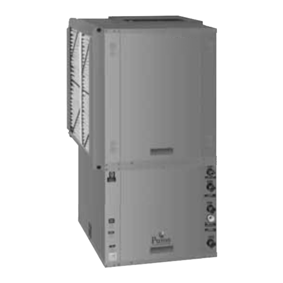
GT-PX Series (50YDV, 50YDH, 50YDD Models) GT-PG Series
Installation, Operation and Maintenance Instructions
Table of Contents
3
4
4
5
7
8
8
9
11
11-12
13
15
16-18
19
20
21
21
(50YEV, 50 YEH, 50YED Models)
Residential Horizontal & Vertical Packaged
Geothermal Heat Pumps
97B0046N03
Revised 4 Jan., 2012
22
23
24-25
26-28
29
30-32
33
34
35
36-41
42
43-44
45-46
47
48
52
Advertisement
Table of Contents
Troubleshooting

Related Manuals for Carrier 50YDV


Summary of Contents for Carrier 50YDV
-
Page 1: Table Of Contents
GT-PX Series (50YDV, 50YDH, 50YDD Models) GT-PG Series (50YEV, 50 YEH, 50YED Models) Installation, Operation and Maintenance Instructions Residential Horizontal & Vertical Packaged Geothermal Heat Pumps 97B0046N03 Revised 4 Jan., 2012 Table of Contents Model Nomenclature Water Valve Wiring Storage... - Page 2 This page was intentionally left blank.
-
Page 3: Model Nomenclature
® R e s i d e n t i a l P a c k a g e d U n i t s - 6 0 H z P u r o n R e v. : 4 J a n . , 2 0 1 2 Model Nomenclature: General Overview Y E V UNIT TYPE:... -
Page 4: Storage
® R e s i d e n t i a l P a c k a g e d U n i t s - 6 0 H z P u r o n R e v. : 4 J a n . , 2 0 1 2 General Information Storage Pre-Installation... -
Page 5: Horizontal Installation
® R e s i d e n t i a l P a c k a g e d U n i t s - 6 0 H z P u r o n R e v. : 4 J a n . , 2 0 1 2 Horizontal Installation Mounting Horizontal Units Horizontal Unit Location... - Page 6 ® R e s i d e n t i a l P a c k a g e d U n i t s - 6 0 H z P u r o n R e v. : 4 J a n . , 2 0 1 2 Horizontal Installation Figure 3: Typical Horizontal Unit Installation Air Coil - To obtain maximum performance, the air coil should...
-
Page 7: Field Conversion Of Air Discharge
® R e s i d e n t i a l P a c k a g e d U n i t s - 6 0 H z P u r o n R e v. : 4 J a n . , 2 0 1 2 Field Conversion of Air Discharge Overview - Horizontal units can be fi... -
Page 8: Duct System Installation
® R e s i d e n t i a l P a c k a g e d U n i t s - 6 0 H z P u r o n R e v. : 4 J a n . , 2 0 1 2 Horizontal Installation Condensate Piping Figure 6: Horizontal Condensate Connection... -
Page 9: Vertical Installation
® R e s i d e n t i a l P a c k a g e d U n i t s - 6 0 H z P u r o n R e v. : 4 J a n . , 2 0 1 2 Vertical Installation Figure 7: Vertical Unit Mounting Vertical Unit Location... - Page 10 ® R e s i d e n t i a l P a c k a g e d U n i t s - 6 0 H z P u r o n R e v. : 4 J a n . , 2 0 1 2 Vertical Installation Sound Attenuation for Vertical Units - Sound attenuation Condensate Piping for Vertical Units - Vertical units utilize...
-
Page 11: Water Connections
® R e s i d e n t i a l P a c k a g e d U n i t s - 6 0 H z P u r o n R e v. : 4 J a n . , 2 0 1 2 Water Connection Installation The female locking ring is threaded onto the pipe threads External Flow Controller Mounting... - Page 12 ® R e s i d e n t i a l P a c k a g e d U n i t s - 6 0 H z P u r o n R e v. : 4 J a n . , 2 0 1 2 Ground-Loop Heat Pump Applications antifreeze solution is used in most areas to prevent freezing.
-
Page 13: Open Loop - Ground Water Systems
® R e s i d e n t i a l P a c k a g e d U n i t s - 6 0 H z P u r o n R e v. : 4 J a n . , 2 0 1 2 Ground-Loop Heat Pump Applications Open Loop - Ground Water Systems Table 2: Antifreeze Percentages by Volume... - Page 14 ® R e s i d e n t i a l P a c k a g e d U n i t s - 6 0 H z P u r o n R e v. : 4 J a n . , 2 0 1 2 Ground-Water Heat Pump Applications valve or water control valve on the discharge line.
-
Page 15: Water Quality Standards
® R e s i d e n t i a l P a c k a g e d U n i t s - 6 0 H z P u r o n R e v. : 4 J a n . , 2 0 1 2 Water Quality Standards Table 3: Water Quality Standards Water Quality... -
Page 16: Hot Water Generator
® R e s i d e n t i a l P a c k a g e d U n i t s - 6 0 H z P u r o n R e v. : 4 J a n . , 2 0 1 2 Hot Water Generator The HWG (Hot Water Generator) or desuperheater option Electric water heaters are recommended. - Page 17 ® R e s i d e n t i a l P a c k a g e d U n i t s - 6 0 H z P u r o n R e v. : 4 J a n . , 2 0 1 2 Hot Water Generator ANTI-SCALD Installation...
-
Page 18: Hot Water Generator
® R e s i d e n t i a l P a c k a g e d U n i t s - 6 0 H z P u r o n R e v. : 4 J a n . , 2 0 1 2 Hot Water Generator Warning! The HWG pump Is fully wired from the 5. -
Page 19: Electrical - Line Voltage
® R e s i d e n t i a l P a c k a g e d U n i t s - 6 0 H z P u r o n R e v. : 4 J a n . , 2 0 1 2 Electrical - Line Voltage WARNING! CAUTION! -
Page 20: Electrical - Power Wiring
® R e s i d e n t i a l P a c k a g e d U n i t s - 6 0 H z P u r o n R e v. : 4 J a n . , 2 0 1 2 Electrical - Line Voltage Figure 16: GT-PX/GT-PG Single Phase Line Voltage WARNING! -
Page 21: Electrical - Low Voltage Wiring
® R e s i d e n t i a l P a c k a g e d U n i t s - 6 0 H z P u r o n R e v. : 4 J a n . , 2 0 1 2 Electrical - Low Voltage Wiring Thermostat Connections Low Water Temperature Cutout Selection... -
Page 22: Water Valve Wiring
® R e s i d e n t i a l P a c k a g e d U n i t s - 6 0 H z P u r o n R e v. : 4 J a n . , 2 0 1 2 Electrical - Low Voltage Wiring Accessory Connections When stage two is operating, both valves will be open,... -
Page 23: Thermostat Wiring
® R e s i d e n t i a l P a c k a g e d U n i t s - 6 0 H z P u r o n R e v. : 4 J a n . , 2 0 1 2 Electrical - Thermostat Wiring Figure 24: Units With Optional ECM Fan. -
Page 24: Ecm Blower Control
® R e s i d e n t i a l P a c k a g e d U n i t s - 6 0 H z P u r o n R e v. : 4 J a n . , 2 0 1 2 ECM Blower Control The ECM fan is controlled by an interface board that position. -
Page 25: Ecm Blower Control
® R e s i d e n t i a l P a c k a g e d U n i t s - 6 0 H z P u r o n R e v. : 4 J a n . , 2 0 1 2 ECM Blower Control Table 5: ECM Board Tap Settings Figure 26a: ECM Version II Interface Layout... -
Page 26: Blower Data
® R e s i d e n t i a l P a c k a g e d U n i t s - 6 0 H z P u r o n R e v. : 4 J a n . , 2 0 1 2 GT-PX (50YD) Series ECM Blower Performance Data Residential Units Only... - Page 27 ® R e s i d e n t i a l P a c k a g e d U n i t s - 6 0 H z P u r o n R e v. : 4 J a n . , 2 0 1 2 GT-PG (50YE) Series PSC Blower Performance Data Airfl...
- Page 28 ® R e s i d e n t i a l P a c k a g e d U n i t s - 6 0 H z P u r o n R e v. : 4 J a n . , 2 0 1 2 GT-PG (50YE) Series ECM Blower Performance Data Residential Units Only...
-
Page 29: Cxm Controls
® R e s i d e n t i a l P a c k a g e d U n i t s - 6 0 H z P u r o n R e v. : 4 J a n . , 2 0 1 2 CXM Controls DDC operation. -
Page 30: Cxm Control Features
® R e s i d e n t i a l P a c k a g e d U n i t s - 6 0 H z P u r o n R e v. : 4 J a n . , 2 0 1 2 CXM Controls Safety Features –... - Page 31 ® R e s i d e n t i a l P a c k a g e d U n i t s - 6 0 H z P u r o n R e v. : 4 J a n . , 2 0 1 2 CXM Controls Safety Features –...
- Page 32 ® R e s i d e n t i a l P a c k a g e d U n i t s - 6 0 H z P u r o n R e v. : 4 J a n . , 2 0 1 2 CXM Controls Safety Features –...
-
Page 33: Unit Commissioning And Operating Conditions
® R e s i d e n t i a l P a c k a g e d U n i t s - 6 0 H z P u r o n R e v. : 4 J a n . , 2 0 1 2 Unit Commissioning And Operating Conditions Operating Limits Environment –... -
Page 34: Unit And System Checkout
® R e s i d e n t i a l P a c k a g e d U n i t s - 6 0 H z P u r o n R e v. : 4 J a n . , 2 0 1 2 Unit Start-Up and Operating Conditions Flow Controller pump(s): Verify that the pump(s) is wired, Unit and System Checkout... -
Page 35: Unit Start-Up Procedure
® R e s i d e n t i a l P a c k a g e d U n i t s - 6 0 H z P u r o n R e v. : 4 J a n . , 2 0 1 2 Unit Start-Up Procedure blocked line. -
Page 36: Unit Operating Conditions
® R e s i d e n t i a l P a c k a g e d U n i t s - 6 0 H z P u r o n R e v. : 4 J a n . , 2 0 1 2 Unit Operating Conditions Table 9a: GT-PX Coax Water Pressure Drop Table 9b: GT-PG Coax Water Pressure Drop... - Page 37 ® R e s i d e n t i a l P a c k a g e d U n i t s - 6 0 H z P u r o n R e v. : 4 J a n . , 2 0 1 2 Unit Operating Conditions Table 11: GT-PX Series Typical Unit Operating Pressures and Temperatures TT026...
- Page 38 ® R e s i d e n t i a l P a c k a g e d U n i t s - 6 0 H z P u r o n R e v. : 4 J a n . , 2 0 1 2 Unit Operating Conditions Table 11: GT-PX Series Typical Unit Operating Pressures and Temperatures: Continued TT064...
- Page 39 ® R e s i d e n t i a l P a c k a g e d U n i t s - 6 0 H z P u r o n R e v. : 4 J a n . , 2 0 1 2 Unit Operating Conditions Table 12: GT-PG Series Typical Unit Operating Pressures and Temperatures: Continued Full Load Cooling - without HWG active...
- Page 40 ® R e s i d e n t i a l P a c k a g e d U n i t s - 6 0 H z P u r o n R e v. : 4 J a n . , 2 0 1 2 Unit Operating Conditions Table 12: GT-PG Series Typical Unit Operating Pressures and Temperatures: Continued Full Load Cooling - without HWG active...
-
Page 41: Unit Operating Conditions
® R e s i d e n t i a l P a c k a g e d U n i t s - 6 0 H z P u r o n R e v. : 4 J a n . , 2 0 1 2 Unit Operating Conditions Table 12: GT-PG Series Typical Unit Operating Pressures and Temperatures: Continued Full Load Cooling - without HWG active... -
Page 42: Preventive Maintenance
® R e s i d e n t i a l P a c k a g e d U n i t s - 6 0 H z P u r o n R e v. : 4 J a n . , 2 0 1 2 Preventive Maintenance Water Coil Maintenance Condensate Drain... -
Page 43: Troubleshooting
® R e s i d e n t i a l P a c k a g e d U n i t s - 6 0 H z P u r o n R e v. : 4 J a n . , 2 0 1 2 Troubleshooting General Test Mode... - Page 44 ® R e s i d e n t i a l P a c k a g e d U n i t s - 6 0 H z P u r o n R e v. : 4 J a n . , 2 0 1 2 CXM Process Flow Chart WARNING! WARNING! HAZARDOUS VOLTAGE! DISCONNECT...
-
Page 45: Functional Troubleshooting
® R e s i d e n t i a l P a c k a g e d U n i t s - 6 0 H z P u r o n R e v. : 4 J a n . , 2 0 1 2 Functional Troubleshooting Fault Htg Clg Possible Cause... - Page 46 ® R e s i d e n t i a l P a c k a g e d U n i t s - 6 0 H z P u r o n R e v. : 4 J a n . , 2 0 1 2 Functional Troubleshooting Thermostat wiring Check G wiring at heat pump.
-
Page 47: Troubleshooting Form
® R e s i d e n t i a l P a c k a g e d U n i t s - 6 0 H z P u r o n R e v. : 4 J a n . , 2 0 1 2 Troubleshooting Form Refrigerant Circuit Diagram Look up pressure drop in... -
Page 48: Warranty
® R e s i d e n t i a l P a c k a g e d U n i t s - 6 0 H z P u r o n R e v. : 4 J a n . , 2 0 1 2 Warranty... - Page 49 ® R e s i d e n t i a l P a c k a g e d U n i t s - 6 0 H z P u r o n R e v. : 4 J a n . , 2 0 1 2 Notes...
- Page 50 ® R e s i d e n t i a l P a c k a g e d U n i t s - 6 0 H z P u r o n R e v. : 4 J a n . , 2 0 1 2 Notes...
- Page 51 ® R e s i d e n t i a l P a c k a g e d U n i t s - 6 0 H z P u r o n R e v. : 4 J a n . , 2 0 1 2 Notes...
-
Page 52: Revision History
Manufacturer’s opinion or commendation of its products. The management system governing the manufacture of Manufacturer’s products is ISO 9001:2000 certifi ed. © LSB, Inc. 2009...