Table of Contents
Advertisement
Advertisement
Table of Contents

Related Manuals for Craftsman 26462_0


Summary of Contents for Craftsman 26462_0
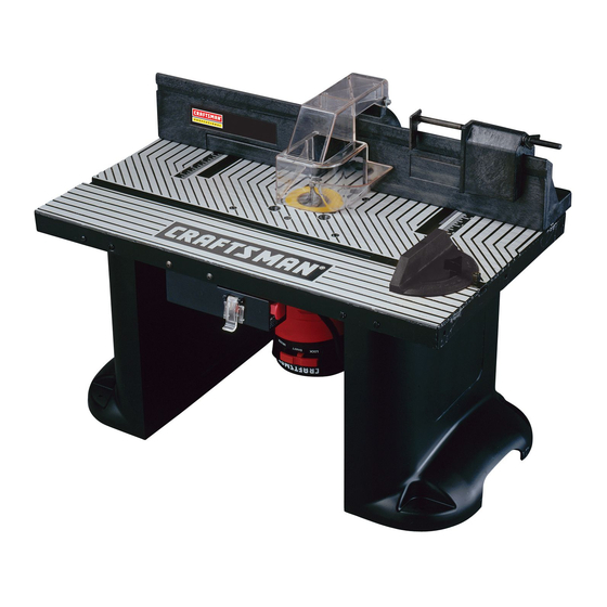
- Page 1 Model No. 26462_0 WARNING: Before operating product, read this manual and follow all its Safety and Operating Instructions. Sears, Roebuck and Co., Hoffman Estates IL 60179 USA 26462 12/00 Printed in U.S.A. CRAFTSMAN o PROFESSIONAL MID-SIZED ROUTER TABLE 4 9LCN-...
-
Page 2: Table Of Contents
Tools Required ... Router Table ... Mounting Router to the Router Table ... Fence Assembly ... Attachment of the Fence Assembly to the Router Table ... Attachment of the Overhead Guard to the Fence Assembly ... Push Block Assembly ... -
Page 3: General Safety Instructions For Power Tools
SAFETY GUIDELINES- This manual contains informa- tion that is important for you to know and understand. This information relates to protect- ing YOUR SAFETY PREVENTING EQUIPMENT PROBLEMS. To help you rec- ognize this information, we use the symbols to the right. Please read the manual pay attention... -
Page 4: Additional Safety Instructions For Router Tables
7. Make sure that the router bit is properly positioned and clamped in the router before making any cuts. 8. Do not use the router table as a workbench or work surface. Doing so may damage it, causing it to be unsafe to use. A workbench should be used for this purpose. -
Page 5: Introduction
• Contact your local Sears Retail Outlet for missing or replacement parts. 26. If ANY of the parts is missing, DO NOT attempt... -
Page 6: Tools Required
NOTE I Legs are positioned to the back edge of the router table, as shown in Figures 1 and 3. 3. Position the leg spacers, two per leg, as shown in Figure 2. Spacers MUST be positioned at the two holes in the front of the router table, as shown in Figure 2. -
Page 7: Mounting Router To The Router Table
Figure 6. Rotate the router until the three threaded holes in the router base line up with the three corre- sponding countersunk holes in the top of the router table. -
Page 8: Fence Assembly
Other Brands of Routers It will be necessary for you to purchase a Craftsman Professional Router Adapter Plate, #25333, from your local Sears Retail Outlet, or through the Sears Catalogue. Routers with a total overall height of 13 inches or less, and a base diameter of 7 inches or less can be accommodated. -
Page 9: Attachment Of The Overhead Guard To The Fence Assembly
4. Repeat steps 1 through 3 for the other side of the fence. 5. Make sure the adjustable jointing fence is inside the router table fence as far as it will go and that the clamping knob has been securely tightened. FIGURE 14... -
Page 10: Push Block Assembly To The Router Table Fence
ProtractOrHead __(_ Plate DUST COLLECTING The router table fence is equipped with a port at the back for the attachment of the hose from a wet/dry vac The port will accommodate a 2-1/2" diameter hose nozzle. To attach, push the nozzle into the port while holding the fence in place. -
Page 11: Alternate Method
1. Cut a board 18-1/4" wide by 24" long from a piece of 3/4" thick wood. 2, Place the router table on the board so that the spac- ing from the edge of the board to the router table legs is equal on all four sides of the board. -
Page 12: Operation
I,_WARNING Use the switch box only when properly assembled to the router table. Use only with a router which has also been properly installed on a properly assembled router table. SWITCH BOX OPERATION This section explains the operation and features of the switch box prior to plugging the power cord into an electrical outlet. -
Page 13: Router And Switch Box Operations
2. To turn the router "ON", slide finger under the switch box cover and toggle the switch box to the "ON" position, as described in the previous section. 3. To turn the router "OFF", press the switch box cover, as described in the previous section. NOTE... -
Page 14: Using The Router Table
AFTER MAKING THIS ADJUSTMENT, BE SURE ROUTER IS SECURELY TIGHTENED IN THE ROUTER BASE, THE BIT IS SECURELY TIGHT- 4. Raise or lower the router until top cutting edge of the manual for adjusting your router properly.) ENED IN THE ROUTER CHUCK AND THE ROUTER BASE IS SECURED TIGHTLY TO THE ROUTER 5. -
Page 15: Edge Cutting With Non-Piloted Router Bits
ROUTER BITS 1. Position the adjustable jointing fence so that its' face is flush with the face of the router table fence. Tighten adjustable jointing fence knob. See Figure 28. 2. Adjust the depth of cut (the material you want to... -
Page 16: Grooving, Fluting, And Veining
I Test cut a scrap piece of wood before making your finished cut. NOTE I When routing deep cuts (controlled by the router bit) in a work piece, remove material in increments to prevent your router from overloading. _crap Nood Repeat operation with several passes until the desired depth is achieved. - Page 17 6. Slide work piece up next to the router bit and adjust the fence and the router, as described in the section, ADJUSTING DEPTH AND HEIGHT OF CUT.
-
Page 18: Routing Using The Miter Gauge
OPERATING POSITION when using the miter gauge. • Always HOLD the work piece FIRMLY and SECURE- LY AGAINST the miter gauge, the router table and the fence assembly when making this cut. • Make sure that NEITHER YOUR FINGERS, HANDS,... -
Page 19: Parts List
PARTS LIST FOR CRAFTSMAN PROFESSIONAL KEY! PART NO. DESCRIPTION RouterTable Assembly Consists of: 29LCN-981 Router Table Top Router Table Leg 29LCN-1283 Table Top Insert (1-1/4" Diameter) 29LCN-996-1 29LCN-996-2 I Table Top Insert (1-7/8" Diameter) Table Top Insert (2-1/8" Diameter) 29LCN-996-3... - Page 20 TABLE ASSEMBLY MISCELLANEOUS PARTS FENCE ASSEMBLY...
- Page 21 MITER BAR ASSEMBLY PUSH BLOCK ASSEMBLY SWITCH ASSEMBLY...
- Page 22 Printed in U.S.A. 12/00 49LCN-84 When corresponding, always give the following information as shown in the list: 1. The PART NUMBER 2. The PART DESCRIPTION 3. The MODEL NUMBER: 26462 4. The ITEM NAME - PROFESSIONAL MID-SIZED ROUTER TABLE...