Advertisement
RATOR'S MANUAL
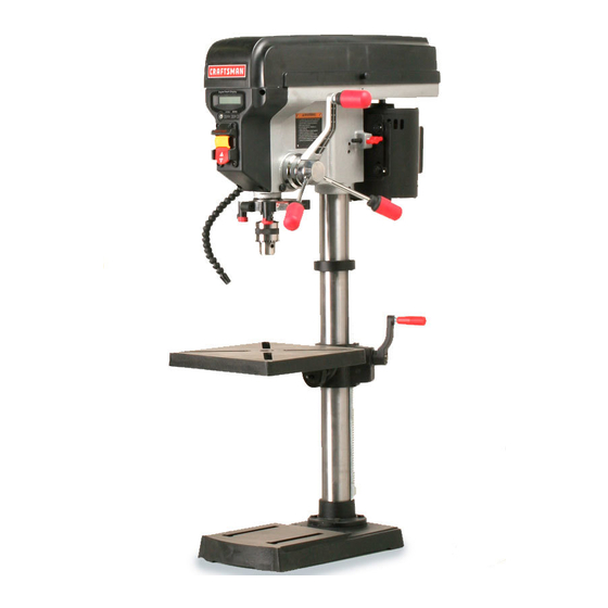
12 in. DRILL P
Model No.
315.219140
_1_ WARNING:
To reduce the risk of injury, the
user must read and understand the operator's
manual before using this product.
Craftsman
Consumer
Hetptine: 1-800-932-3188
Sears,
Roebuck
and Co., 3333 Beverly
Rd., Hoffman
Estates,
IL 60179
USA
Visit the Craftsman
web page: www.sears.com/craftsman
983000-830
01-08-07 (REV:05)
Save this manual
for future
reference
Advertisement
Table of Contents

Related Manuals for Craftsman 21914 - 12 in. Drill Press


Summary of Contents for Craftsman 21914 - 12 in. Drill Press
- Page 1 Craftsman Consumer Hetptine: 1-800-932-3188 Sears, Roebuck and Co., 3333 Beverly Rd., Hoffman Estates, IL 60179 Visit the Craftsman web page: www.sears.com/craftsman 983000-830 01-08-07 (REV:05) Save this manual for future reference...
-
Page 2: One-Year Full Warranty
Back Page ONE-YEAR FULL WARRANTY ON CRAFTSMAN TOOL If this Craftsman tool fails due to a defect in material or workmanship within one year from the date of purchase, CALL 1-800-4-MY-HOME ® TO ARRANGE FOR FREE REPAIR (or replacement if repair proves impossible). This warranty does not include expendable parts such as lamps, batteries, bits, or blades. - Page 3 [] SECURE WORK. Use clamps or a vise to hold work WARNING: Read and understand all instruc- when practical, it is safer than using your hand and tions. Failure to follow all instructions listed below, frees both hands to operate the tool. may result in electric shock, fire and/or serious [] DO NOT OVERREACH.
- Page 4 [] DONOTUSE TOOL IF SWITCH DOES NOT TURN IT [] USE ONLY CORRECT ELECTRICAL DEVICES: 3-wire extension cords that have 3-prong grounding plugs ON AND OFF. Have defective switches replaced by an authorized service center. and 3-pole receptacles that accept the tool's plug. [] KEEP TOOL DRY, CLEAN, AND FREE FROM OiL [] ALWAYS TURN SWITCH OFF before disconnecting AND GREASE.
- Page 5 [] KEEPBiTSCLEAN ANDSHARP. Sharpbitsminimize [] AVOID DIRECT EYE EXPOSURE when using the laser stalling. D irtyanddullbitsmaycausemisalignment of guide. the material andpossible operator i njury. [] NEVER PLACE YOUR FINGERS iN A POSiTiON [] KEEPHANDS AWAYFROM WORK AREA.Keep WHERE THEY COULD CONTACT THE DRILL or hands awayfromthe bit.Restrain a nyloose clothing, other cutting tool if the workpiece should unexpectedly jewelry, l onghair, e tc.,thatmaybecome entangled i n...
-
Page 6: Symbols
Some ofthefollowing symbols maybeusedonthistool.Please studythemandlearn theirmeaning. Proper i nterpreta- tionofthesesymbols willallowyouto operate thetool better andsafer. SYMBOL NAME DESIGNATION/EXPLANATION Volts Voltage Current Amperes Hertz Frequency (cycles per second) Watt Power Minutes Time Alternating Current Type of current Direct Current Type or a characteristic of current No Load Speed Rotational speed, at no load... - Page 7 If you do not understand the warnings and your nearest SEARS PARTS AND REPAIR SERVICE instructions in the operator's manual, do not use this CENTER for repair. When servicing, use only identical product. Call the Craftsman Consumer Helpline at replacement parts. 1-800-932-3188 for assistance.
-
Page 8: Electrical
EXTENSION CORDS SPEED AND WIRING Use only 3-wire extension cords that have 3-prong The no-load speed of this tool is approximately 3,000 rpm. grounding plugs and 3-pole receptacles that accept the This speed is not constant and decreases under a load or tool's plug. - Page 9 Anti=Kickback Pawls Non-Through Cuts (radial arm and table saws) Any cutting operation where the blade does not extend A device which, when properly installed and maintained, completely through the thickness of the workpiece. is designed to stop the workpiece from being kicked back toward the front of the saw during a ripping operation.
-
Page 10: Product Specifications
PRODUCTSPECIFICATIONS Chuck ................Spindle Travel ............3-1/4 in. Table Size ..............10 in. input ....... 120 Volt, 60Hz, AC Only, 6 Amps Motor ............2/3 HP induction Table Movement ....... 45 ° bevel, 360 ° swivel No Load Speed ......500-3,000 r/min (RPM) Overall Height ............ -
Page 11: Know Your Drill Press
FEED HANDLES AND FEED CRANK KNOW YOUR DRILL PRESS Feed handles and feed crank raise and lower the chuck See Figure 2. and bit during the drilling operation. The safe use of this product requires an understanding of the information on the tool and in this operator's LASER ASSEMBLY manual as well as a knowledge of the project you are The laser assembly makes accurate drilling simple and... - Page 12 Thefollowing itemsareincluded withthedrillpress: Chuck Tool ................. Head Assembly ..............Chuck ................Column Assembly ............. Table Assembly ..............ChuckKey ................. Base.................. Adjustable F ence ............... HexKey(2.5,3,4,5, and6 mm) ........Laser A ssembly ..............HexBolts(M8) ..............Mounting BoltAssembly .
-
Page 13: Assembly
[] Donotdiscard the packing material untilyouhave carefully inspected thetool,identified alllooseparts, andsatisfactorily o perated thetool. [] If anypartsaredamaged or missing, p lease callthe Craftsman C onsumer Helpline at 1-800-932-3188 for assistance. COLUMN WARNING:Ifanypartsaredamaged or missing ASSEMBLY do notoperate thistooluntilthepartsarereplaced. - Page 14 iNSTALLINGTABLEASSEMBLY COLUMN See Figures 6 - 8. COLLAR__--_1 [] Loosen the set screw in the column collar. Remove the SCREWS column collar and gear rack from the column and set aside. [] Locate the worm gear and feed the D-shaft through the slot in the table support.
- Page 15 INSTALLING CHUCK, HEAD ASSEMBLY, FEED HANDLES See Figures 9 - 11. NOTE: Move the table out of the way before beginning installation. [] Position the head assembly onto the column with the chuck positioned over the table. NOTE: The head assembly is heavy. Get help when FEED CRANK needed.
-
Page 16: Installing The Batteries
INSTALLING BATTERIES LASER ASSEMBLY LASER See Figure 12. ASSEMBLY To install batteries: [] Lift the battery cover up and remove. UILL [] Install two AA batteries according to polarity indicators inside the battery compartment. To install laser assembly: [] Loosen the hex bolt from the laser assembly. HEX BOLT [] Slide the laser assembly over the chuck and onto the quill. -
Page 17: Mountingthe Drillpress
MOUNTINGTHE DRILLPRESS See Figure 14. If the drill press is to be used in a permanent location, secure it to a workbench or other stable surface. If the drill press is to be used as a portable tool, fasten it permanently to a mounting board that can easily be clamped to a workbench or other stable surface. - Page 18 dl_ WARNING:Donotallowfamiliarity withtoolsto WARNING: Always remove the switch key when make you careless. Remember that a careless frac- the tool is not in use and keep it in a safe place. In tion of a second is sufficient to inflict serious injury. the event of a power failure, turn the switch OFF (O) and remove the key.
- Page 19 TABLEROTATION TABLE See Figure 17. The table can be rotated out of the way when drilling large objects. [] Loosen the table lock handle. LOCK HANDLE [] Rotate the table to the desired position. [] Retighten the table lock handle. SELF-EJECTING CHUCK See Figure 18.
- Page 20 I] Makesuretheworktableisfreeofalllooseobjects andthatthebit is notincontactwiththeworkpiece. I] Plugelectrical cordintopowersupply andturnswitch ON.Makesurespindle rotates freely. I] Slowly lowerdrillbit intoworkpiece. Donotforcethe bit,letthedrillpressdothework. I] Once the holeis completed, raisethespring-loaded feedshaftto itsnormal p osition. Thiswillautomatically raisethechuckandbit. DRILLING TIPS If the hole is large, it's a good idea to drill a smaller pilot hole before drilling the final one.
- Page 21 Withthetool inthe OFF( O) position, l ower thedrill DIGITAL DEPTH bit byturning thefeedhandles untilthedrillbittouches the workpiece. Holdin thisposition andpress the zero resetbutton. NOTE: T hissetsthedepthto zeroatthesurface ofthe ON/OFF workpiece. BUTTON D Remove t heworkpiece thenincrease t he depthof the drillbit (past z ero)untilthedesired depthis displayed. Holdinthisposition andlockthedepthusingthelock knobto limitdrilling depth.
- Page 22 CHANGINGSPEEDS SPINDLE DRIVE MOTOR PULLEY BELT PULLEY See Figure 25. The spindle speed is determined by the location of the belt on the pulleys inside the head assembly. The speed chart located on the cover inside the head assembly shows the recommended speed and pulley configuration for each drilling operation.
-
Page 23: Maintenance
HEAD ASSEMBLY AND MOTOR HOUSING _k WARNING:Whenservicing, useonlyidentical re- Frequently blow out any dust that may accumulate inside placement parts.Useofanyotherpartsmaycreate the head assembly and/or motor housing. a hazard orcauseproductdamage. PULLEYS _IL WARNING:Always wearsafety goggles or safety See Figure 26. glasses withsideshields duringpower tooloperation Should you feel an unusually high level of vibration, the or whenblowing dust.Ifoperation is dusty, a lsowear pulleys may not be tightly secured on the motor and/or... -
Page 24: Drill Press
CRAFTSMAN DRILL PRESS- MODEL NO. 219140 Part Number Description Qty. Number Description Qty. 089140301146 089140301085 Shaft Pinion ........Logo Label ........089140301001 Cover ..........089140301099 Roll Pin (D5 x 16 ram) ....... 1 089140301150 089140301002 Cover Button ........Warning Label ........ - Page 25 CRAFTSMAN DRILL PRESS- MODEL NO. 219140 _--=- .._---- "=_'--'- Part Part Humber Description Qty. Humber Description Qty. 089140301154 Chuck Tool ........089140301092 Set Screw (M6 x 10 mm) ....2 089140301120 Column Collar ........ 089140301093 *Washer (M9 x M28 x 3t) ....4 089140301129 Hex Bolt .........