Table of Contents
Advertisement
Operator's Manual
11,0 AmptVariable
Speed/,?. Peak HP
Router
with Fixed Base
and Plunge Base
Model
No.
320.17543
?
Z_ CAUTION
Read, understand and follow
afi Safety Rules and Operating Instructions
in this Manual before using this product
Sears, Roebuck and Co.
Hoffman Estates, IL 60179 U_S,A,
Visit our Craftsman webslte: www,craftaman,com
• WARRANTY
• SAFETY
• UNPACKING
• DESCRIPTION
• ASSEMEI LY
• OPERATION
o ADJUSTMENTS
• MAINTENANCE
9/6/06
4:45pm
Advertisement
Table of Contents

Related Manuals for Craftsman 320.17543


Summary of Contents for Craftsman 320.17543
- Page 1 Safety Rules and Operating Instructions • DESCRIPTION in this Manual before using this product • ASSEMEI LY • OPERATION Sears, Roebuck and Co. Hoffman Estates, IL 60179 U_S,A, o ADJUSTMENTS Visit our Craftsman webslte: www,craftaman,com • MAINTENANCE 9/6/06 4:45pm...
- Page 2 Sears Repair Paris Phone Numbers ........Back Cover ONEYEAR FULL WARRANTY ON CRAFTSMAN" PRODUCT llf th_s Craftsman product Iaiis due to a defecl In material or workmanship wllhln one year item lhe date of purchase, RETURN IT TO THE NEAREST...
- Page 3 ALWAYS wear safety goggles or safety glasses with side shield end a full*face shield when needed°We recommend a Wide Vision Safety Mask for use over eyeglasses or standard safety glasses with slde shleld, available at Sears Stores or other Craftsman® Outlets° 17543...
- Page 4 manual before using these reuters. Failure to follow all Instructions may result I Z_ WARNING: BE SURE to read end understand sn Instructions in this electric shock, fire and/or serious personal injury° WORK AREA SAFETY Keepyourworkarescleanandweltllt°Clutleredworkbenchesanddarkaress invite accidents, DO NOT operate power tools In explosive atmospheres, such as In the presence...
- Page 5 TOOL USE AND CARE SAFETY operating these reuters. Failure to follow all instructions listed below may result I L_ WARNING: BE SURE to read end understand all Instructions before In electric shock, fire andtor serious personal injury. 1 ALWAYS use clamps or other practical ways to secure and support the workplace to a stable platform, Holding the work by hand or against your body Is unstable and may teed to loss of control 2 DO NOT force the tool.
- Page 6 ELECTRICAL SAFETY cent. 3 BEFORE plugging tn the tool, BE SURE that the outlet vollage supplied Is w_lhtnthe voltage marked on the Iool's data plate DO NOT use "AC only" rated fools with a DC power supply 4 AVOID body contact with grounded surfaces, such as pipes, radiators,ranges and refrigeratorsThere Is an increased riskof electric shock If your body Is grounded 5 DO NOT expose power toots to rain or wet conditions or use power toots In wet or damp locations...
- Page 7 SERVICE SAFETY 1 If any part of this router combo kit is mlsstng or shou|d break, bend, or fell in any way; or should any electrical component fall to perform property: SHUT OFF the power switch and remove the router plug from the power source and have the missing, damaged or ladled pads replaced...
- Page 8 SAFETY RULES FOR REUTERS conL MAKE SURE Ihe cutter btt Is not In contact wlth the workpiece before the switch Is turned on.The bit must ALWAYS be running at full speed before contacting the workpleceo KEEP HANDS CLEAR OF CUTTER BIT when motor Is running to prevent personal Injury.
- Page 9 z_ WARNING: Use of this toot can generate dust containing chemicals known to cause cancer, birth defects or other reproductive harm.. Some examples of these chemicals are: • Lead from lead-based paints ,, Crystalline silica from bricks and cement and other masonry produels •...
- Page 10 (refer to I{lustrat_on "Parrs List" on page !t), return the Rouler Combo Kit to your nearest Sears store or Craftsman oullel Io have It replaced Z_ WARNING: If any parts ere broken or missing, DO NOT attempt to plug in the power cord or operate router until the broken or missing parts are...
- Page 11 3, Heavy-duty Edge Guide 5, (for ettachfng Hoods) 4 Screws _dP _ P_p 6_ 1i4_ln Collar/Nut _ 7- CotfeUNutWrench KNOWYOUR ROUTER KIT (FIg_ 2) NOTE: Before attempting to use your router_familiarize yourself w_lh atl of the operating features and safety raqutremantso Your fouler has a precls{on bui!t electric motor and it should be connected to a 120*volL 6O-HzAC ONLY powersupply (normal household current) DO NOT operate on direct current (DC) This large voltagedrop wilt cause a loss o! power and the motor will overheat...
- Page 12 KNOWYOUR ROUTER KIT cont. (Fig. 2) This Router Combo Kit has the following features: 1to0 Amp, 2 Peek HP, Vartable Speed Motor rues a! 12_000 to 25,000 (no-load speed) Varlebta Speed Dial allows matching proper speed _o material and cut_er bit size Electronic Feedback Circuitry...
- Page 13 KNOWYOUR ROUTER KIT conL (Fig° 2) Depfl'_,Rod Micro Adjust Knob ..Quick.Clam- B_e Ko_s_lip5 ot uop_n _cale Motor C_an_'In (En_age_ Molor •\ S,,slem - Housing KoystHp) Lo_Ing LOVer Hand_o_ r_Dopth _ndica_or ,_ Sort-Grip Locking Knob wffhP?olor_Ivo Cloar Edge Gulde ;_ul_.Bas_ Edge Gu_ Loc_n_ Knob Moon,trig 510_...
- Page 14 Install a sub-base with a larger opening, sold separately at Sears stores or other Craftsman outlets, Z_ WARNING: When using router cutter bits with a cutter diameter larger than 1 V2-1nches, ALWAYS have the speed dial set at number 1 or 2.. Refer to the...
- Page 15 SELECTING THE CUTTER BIT cont. WARNING: ALWAYSturn motor off and unplug router before making any adjustments or Installing acceseortaS,r Failure to unplug the router could result In accidental starting which can cause serious personal inJuty_ Fig, 4 INSTALLING THE CUTTER BIT 1 Turn motor off and unplug frompower source 2 Remove motor housing from fixed or plunge base NOTE: See Instructions on Installing end removing the motor housing from the...
- Page 16 REMOVING THE CUTTER BIT (Figs, 3 and 4 see page 15) 1 Turn motor off and unpfug Item power source 2 Remove motor from fixed or plunge base 3 Set the motor upside down on Its top cap. with co!la!/nutpointing up 4 Press spindle ]ockbutton Io engage and tockthesptndle shaft and conettnut,(Fig 3) 5 Place the wrenchon the colle_nut and turn counter- clockwise and tooeen collegnut slightly and remove cutter bit shank...
- Page 17 To install Motor In Fixed Base (Fig, 5) 1 Turn moloroffsnd Unplug from power source 2 Place fixed base on flatsurface 3 With back of fixed base facing you, open motor clamp (A) 4 Press in Coarse Adjustment Knob (B) Iodepart thegears (C) while you align the motor houslng's keystrlp (D) with the keystdp-elot (E) In the fixed base...
- Page 18 REMOVING MOTOR FROM BASES To Remove Motor From Fixed Base (see Fig. 5, on page Turn motor elf and unplug from power source Place router (lixed base!motor housing) on fiat surface With back of router facing you. open the motor clamp Push in coarse adjustment...
- Page 19 Coarse Adjustment Depressing fhe Coarse Adjustment Knob (B) allows you to quickly lower or raise Ihe cutter bit to a larger or approximate depth setting Fine Adjuslment adjustments,Test it by turning the Fine Adjustment Dial (C) clockwise counter-clockwise to see tf the bit lowers end raises if tt does not, press in the Coarse...
- Page 20 NOTE: Making a single deep cut Is never advisable,, Smaller diameter cutter bits are easily broken by too much side thrust and torque Larger cutter bits wile cause a rough cut and be difficult to guide and control For these reasons, DO NOT EXCEED 1/8-1N DEPTH OF CUT In a stogie...
- Page 21 DEPTH_STOP ROD AND DEPTH-STOP TURRET (Figs. 10 end 11) The Depth-Stop Rod end the Depth-Stop Turret are used to control the cutting depth as follows: Turn motor off and unplug frompower source With the cuttingbit already Installed, lower the plunge action until the cutler bit makes contact wilh the flat, level surface fha router Is Wtllng on, Lock the plunge depth locking laver (F), This position is ZERO ="0"...
- Page 22 Making Deep Cuts with the Depth-Stop Turret (Ftg_11) NOTE: Making a single deep cut is never advisable..Smaller diameter cutter bits ere easily broken by too much side thrust and torque, Larger cutter bits will cause a rough cut end be difficult to guide and control. For these reasons, DO NOT EXCEED 1t8-1N DEPTH OF CUT In a stngla pass.
- Page 23 TOGGLE "ON/OFF" SWITCH (Fig. Your router motor Is turned "ON" and '_OFF" by the toggle switch located on the top cap of the motor housing The tell side of the toggle switch hood (as you lace it) is marked "1"for "On" and lhe right side {as you face it) is marked "O"...
- Page 24 HEAVY-DUTY EDGE GUIDE (Figs. 15 and 15a) Your Router Combo Kit comes w}tha Heavy-Duty Edge Guide This edge guide can be used as an aid In routing appticat_ons such as decorative edging, straight edgeplanning and trimm_ng,grooving, dadoing and stetting To assemble onto fixed or plunge bases, simply Insert edge guide rods into edge guide mounting slots, adjust to desired position, and lock down with the edge guide locking knobs Fig, t5 Usin...
- Page 25 ..Variable speed Selection Chart ..Never exceed these bit speeds Cutter Bit Diameter Max_ Speed Up to l-in,, (25mm) 1 1/4-1n, to 2-1n, (30-50ram) 4 - 5 2 1/4-1no to 2 112-1n, (55-65 ram) 2 - 3 3-In, to 3 1/2-tn, (75-90mm) I - 2 Reduce lhe speed when using extra forge t-{n, plus, or heavy cutter bits...
- Page 26 EDGE ROUTING OR INTERNAL ROUTING For ease of operation and Io matnia{n proper control, your router has !we handles. end on sach side of the router base When operating the router, a_ways hold it [irmty witl_ both hands {see Fig 16 and 16a ) Turn the router "On', let lhe motor build to its lull speed, then gradually feed the...
- Page 27 INTERNAL ROUTING WITH FIXED BASE (Figs, 17, 17a, 17b and !8) 1 WIIh doplh-of-culseL tilt fixed base router and p_aceon workptecewiIh leading edge of sub-bass conlacIIng workpIece lirst (Fig17) 2 Turn motor "On" and lel motor build up to Its fult speed, be careful not to let cutter bii contact the workptece 3 To begin your cut, gradually feed the cutler bit Into the workplace unlit the subbase Is level with the workplece (see Fig 17a and 17b)
- Page 28 INTERNAL ROUTING WITH PLUNGE BASE (Flgso 19 and 19a) 1 Wilhdeplh-of_culset, andlhoplungeactionlockedtntheralsed{Up)poslgon, lure motor "On" and lel motor build up to its lull speed (see Fig 19) 2 To begin your cul, unlock the plunge lock lover and gsntlylowar the plunge action down evenly Into the workpiece (see Fig 19a) Feed Direction 3 When the desired depth-of-cut is achieved, lock the plunge lock lover (Down) and...
- Page 29 FREEHAND ROUTING WITHTHE FIXED BASE (Fig.. 20) Z_ WARNING: Do not use large cutter bits for freehand routtng_ Use of large cutter bits when freehand routing could cause loss of control or create other hazardous conditions that could result In personal injury- if using a router labia, large b ts shou d be used for edging...
- Page 30 EDGING WITH A PILOT BIT (Figs. 21 and 21a) The arbor4ype bile wtth pilots are excellent for edge shaping of any workplace edge that is eiItler straight, or curved at a cuwature as greal or greater than lhe radius st the bit to be used The pilot prevents the bit from making too deep a cut;...
- Page 31 FEEDING THE ROUTER (Fig, 22) The secret to professional fouling Is tn making a carefu{ set-up (or the cut, setecltng the proper depth of cut, knowing how the culler bit reacls in your workpieca, and the rate and d_rectfonof feed of (he router Fig.
- Page 32 DIRECTION OF FEED - INTERNAL CUTS (Figs 23 and 23a) When making an interest cut, such as a groove dado or slot, always have the guide you ere using with the router (edge guide, straight edge_ board guide) on the right-hand side of ti_e rosier as you make your ca|, (see Fig 23) When the guide Is positioned...
- Page 33 RATE O F FEED ( Flgs_ 24 and 24a) The proper rate of teed depends on severa_ factors: the hardness and moisture content of the workptece,the depth of cut, and the cutting diameler of theblL When you are cutting shallow grooves In soft woods such as plne, you may use a faster rate of feed When making deep cute in hardwoods such as oak, you should use a slower rate of feed FEEDINGTOO FAST (Flgo 24)
- Page 34 CHIP SHIELD DEFLECTORS (Figs, 25 and 25a) Z_ WARNING: ALWAYSwear eys protection, The chip shletd deflectors are not intended as s safety guard, To removechipshletdfrom fixed bess, pressinward on tabs anlil chip shiefdretsases from base and removeiLTo attach, piece chip shieldback inposilion andtlex sides while pushingit inuntil ii snaps back intoplace(See Fig 25) The chip shield defleclor on the plunge base ls hetd in positionby a screw, To remove the chip shield from the plurtge base, simply remove the screw and take...
- Page 35 DUST EXTRACTION HOODS (Figs,, 26 and 26a) There are dust extraction hoods Includedwilh each fouler base Eachhood is sized toaccept a IVz-in vachose adapler, sold separatel_ Dust Extraction Hood for Ptung Base (Fig, 26) To altach the hood onto the plunge base, position and secure it Io the back of the base with 1he lwo screws (included) as shown...
- Page 36 motor from the power source before performing any maintenance or cleaning Z_ WARNING; For your safety, ALWAYS turn off switch and unplug reuter It has been foundthat electric tools are subject Io accelerated wear and possible premature lallure when theyare used 1oworkon fiber glass boats and sports cars, wallboard, spackling compounds or plaster The chipsand gdndlngs from these materials are highlyabrasiveto electricaltool paris, such as bearings, brushes, commutators, elc Consequenl}y, it is not recommendedlhat Ibis toot be used forextended work on any...
- Page 37 REPLACEMENT OF CARBON BRUSHES (Ffg_ 27) Replacement brush sets are available throughSears Partsand Repair Centers 1 Unplug the _routermotor before inspecting or replacing brushes 2 Replace both carbon brushes when either has tess than 1/4-In length of carbon remaining, or if the spring or wire Is damaged or burned 3 Using a stetted screwdriver, remove the btack plasticcap on each side of the router motor (Fig 27) and carefullywithdraw Ihe sprlng-foaded brush assemblies Keep brushes clean and sliding freely in their guide channels,...
- Page 38 In serious Injury Seers and other Craftsman == outlets offer a large selection of Craftsman router accessories designed for specific routing applications straight There is a large selection _11tIlght _ll@ght...
- Page 39 In addition to a wide variety el router bits, Sears also otters accessories such as', Router fables, various template sels, unlversal router fence with Iock knobs (64181). 1t pc bushing set (64180) and clear sub-base sets; 6pc fixed base (64182) 6 pc p_unge base (64183) b_ad and cove bead cove...
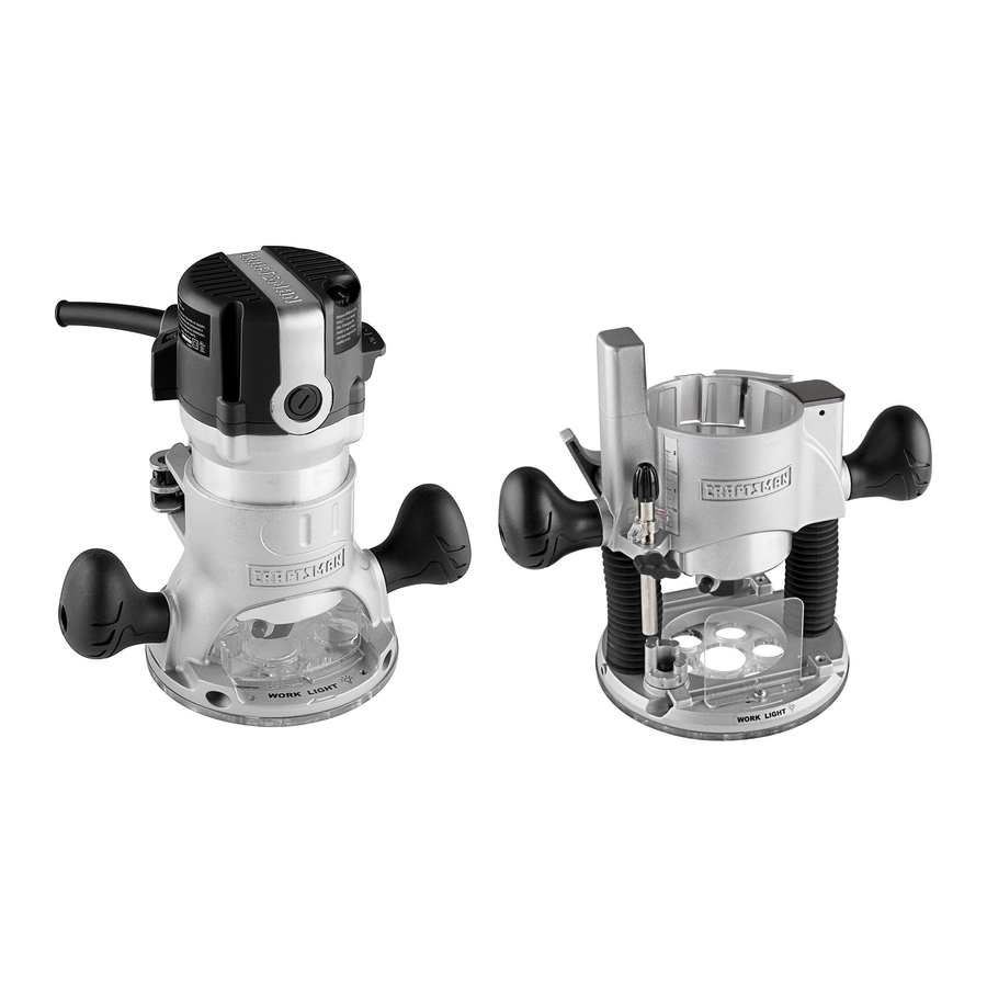
- Page 40 11.0 Amp/Variable Speed/2 Peak HP - MODEL NUMBER 320.17543 The Model Number witl be found on the Nameplate. Always mention the Modet Number in ell correspondence regarding your tool Motor Unit "= • J,r--7_I ' ,i...
- Page 41 11.0 AmplVariable Speed/2 Peak HP - MODEL NUMBER 320.17543 "The Modet Number wilt be found on the Nameplate Atways mention the Model Number +nalt correspondence regarding your tool Fixed Base ,_'jP • ).,-'_ " _ , /'_ • • +,:1_' "_ '-- ..
- Page 42 11.0 Amp/Variable Speed/2 Peak HP - MODEL NUMBER 320.17543 3"he Model Number wilt be found on the Namepiale, Always mention the Model Number in eli correspondence regarding your tool Plunge Base • /l...
- Page 43 11,0 Amp/Variable Speed/2 Peak HP - MODEL NUMBER 320.17543 The Model Number will be found on Ihe Nameplate Always mention the Model Number in all correspondence regarding your Ioof Edge Guide ,, _ _t,! 17543...
- Page 44 11.0 Amp/Variable Speed/2 Peak HP -- MODEL NUMBER 320.17543 The MocieF Number will be found on tha Namepla{e. Atways mention the Mode_ Numbar in all correspondBnce regarding your {oot Item No, Parts No. Part Description Qty. 3700798000 Decorate Cover 5510059000 Screw 3121689000 Rear Cover...
- Page 45 11.0 Amp/Variable Speed/2 Peak HP - MODEL NUMBER 320.17543 The Model Number will be found on the Nameplate. AIways mention the Model Number in a_l correspondence regarding your tool Item No. Parts No. Part Descriptfon Qty-. 8822039000 Internal Wire lelernal Wire 2622036000 Screw 5620032000...
- Page 46 11.0 Amp/Variable Speed/2 Peak HP - MODEL NUMBER 320.17543 The Model Number wlll be found on the Namep_ale, Always menlion the Model Number in alf correspondence regarding your loot Item No. Paris Part Descrtplian Qty. 3121637000 Chip Shield 3420390000 Mounting 5620041000 Screw 3121648000...
- Page 47 17543...
- Page 48 Get it fixed, at your home or ours! HO#TI_ YOU{ FnT repair - in your home - of all major brand appliances, lawn and garden equipment er heating and cooling systems no matter who made it, no matter wllo sold it! For the replacement pa_ts accessorJes and owner s manuals that you need to do-it,yourael[...