Table of Contents
Advertisement
Available languages
Available languages
Quick Links
Operator's
Manual
CRA
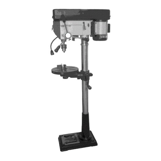
15-in. DRILL PRESS
3/4 HP MOTOR
Model 124.34984
CAUTION:
Before using this
product,
read this manual and
follow all its Safety Rules
and Operating
Instructions.
® Safety Instructions
® Assembly
® Operation
® Maintenance
® Troubleshooting
® Parts List
• Espa_ol
Sears Brands
Management
Corporation,
Hoffman
Estates,
IL 60179 U.S.A
Advertisement
Table of Contents

Related Manuals for Craftsman 124.34984


Summary of Contents for Craftsman 124.34984
- Page 1 Operator's Manual 15-in. DRILL PRESS 3/4 HP MOTOR Model 124.34984 CAUTION: Before using this ® Safety Instructions product, read this manual and ® Assembly follow all its Safety Rules ® Operation ® Maintenance and Operating Instructions. ® Troubleshooting ® Parts List •...
- Page 2 For warranty coverage details to obtain free repair or replacement, visit the web site: www.craftsman.com This warranty is void if this product is ever used while providing commercial services or if rented to another person. This warranty gives you specific legal rights, and you may also have other rights which vary from state to state.
- Page 3 17. NEVER STAND ON TOOL. Serious injury could occur if the 21. MAINTAIN TOOLS WITH CARE. Keep tools sharp and clean tool is tipped or if the cutting tool is unintentionally contacted. for best and safest performance. Follow instructions for 18.
- Page 4 BASE - Supports drill press. For additional stability, holes DRILLING SPEED - Changed by placing the belt in are provided in base to bolt drill press to bench. any of the steps (grooves) in the pulleys. See the Spindle Speed Chart inside belt guard or in the manual. BACKUP MATERIAL - A piece of scrap wood placed...
- Page 5 ELECTRICAL REQUIREMENTS POWER SUPPLY AND MOTOR SPECiFiCATiONS WARNING: To avoid electrical hazards, fire hazards, or damage to the tool, use proper circuit protection. Use a separate electrical circuit for your tools. To avoid shock or fire, if power cord is worn or cut, or dam- aged in any way, have it replaced immediately.
- Page 6 CARTON CONTENTS UNPACKING AND CHECKING CONTENTS Carefully unpack the Drill Press and all its parts, and compare against the illustration following. WARNING: • To avoid injury from unexpected starting, do not plug the power cord into a power source receptacle during unpacking and assembly. This cord must remain unplugged whenever you are assembling or adjusting the drill press.
- Page 7 B. Accessories (in one separate box) See Fig.2 B. Crank handle C. Hex wrenches D. Hex bolts A. Feed handles E. Chuck key F. 5/8=inch Chuck and chuck removal tool G Table fence set Table Fence Use the supplied hardware to attach the fence to the table as shown in the picture below. Use the fence to align the workpiece and provide a backstop for secure drilling.
- Page 8 1. Column support to base 1.1 Position the base on floor or bench. 1.2 Place the column on the base, aligning the holes in the column support with the holes in the base. 1.3 Locate the four long hex bolts from the loose parts bag. 1.4 Place a bolt in each hole through the column support and the base.
- Page 9 5. Installing the chuck WARNING: Before any assembly of the chuck and arbor to the drill press head, clean all mating surfaces with a non-petroleum based product; such as alcohol or lacquer thinner. Any oil or grease used in the packing of these parts must be removed;...
- Page 10 1. Table adjustment A. Tilting adjustment - On underside of table support bracket, back out set screw with supplied hex wrench, Loosen large hex head bolt, See Fig, 9 - Rotate table to desired angle right or left. Use bevel scale for precise setting, See Fig, 10 - Tighten hex head bolt to secure table tilt.
- Page 11 WARNING: To prevent personal injury, always disconnect the plug from the power source when making any adjustment. 2. Feed Depth Adjustment The depth gauge is located on the feed handle hub. Use the depth gauge to accurately and consistently set the required drilling depth. Loosen the depth stop fixing screw, set the depth stop as required and subsequently re-tighten the fixing screw.
- Page 12 WARNING! 6. ADJUSTING THE LASER LINE LASER RADIATION: AVOID DIRECT EYE CONTACT NOTE: Laser pointer (1) is an alternative part. Your • A Laser light is radiated when the laser guide is turned machine may not have this laser pointer. on.
- Page 13 1. Installing A Drill Bit See Fig. 16 1.1. With the switch "OFF", open the chuck jaws (1) using the chuck key (2). Turn the chuck key counterclockwise to open the chuck jaws (1). 1.2. Insert the drill bit (3) into the chuck far enough to obtain maximum gripping by the jaws, but not far enough to touch the spiral grooves (flutes) of the drill bit when the jaws are tightened.
- Page 14 Correct Drilling Speeds WARNING: Be sure drill press is turned off and is disconnected from power sours before adjusting speeds. Use the recommended speed for the drill bit and workpiece. The drill bits that can be used are shown in following figure: DRILL _POINT FOR_ER...
- Page 15 MAiNTAiNiNG YOUR DRILL PRESS LUBRICATION All of the drill press ball bearings are packed with grease WARNING: For your own safety, turn the switch OFF and at the factory, They require no further lubrication, Lower remove the plug from the power source outlet before main- spindle to maximum depth and oil moderately once every taining or lubricating your drill press.
- Page 16 _55--4 /_35-5 51--...
- Page 17 KEY NO. MFG. PART NO. QUANTITY O-belt Small belt pulley Bolt Bearing Middle pulley Shaft Pulley cover Knob Flat washer Toothed washer Bolt Nameplate lable Speedlable Bolt Flat washer Coil Spindle pulley Q-belt Strain relief Bearing Lantern ring Bearing Spring washer Fiat washer Line clamp Rubber wasner...
- Page 18 KEY NO. MFG. PART NO. QUANTITY Bolt Switch Reduction vibration ring Retaining ring _eanna Track s'leeve Wedge Beanna _.pindl_ uone snaft Chuck assembly Bolt ,Spring washer LOCKna nanate assembly Bracket Lable Rivet Table Angle lable r_Jvet 70-1 Bolt 70-2 Flat washer 70-3 Knob 70-4...
- Page 19 Agreements Congratulations on making a smart purchase. Your new Craftsman® product is designed and manufactured for years of dependable operation. But like all products, it may require repair from time to time. That's when having a Repair Protection Agreement can save you money and aggravation.
- Page 20 Para la cobertura de garant[a los detalles para conseguir reparaci6n gratuita o reemplazo, visite el sitio web: www.craftsman.com Esta garant[a le da derechos legales especificos, y tambien podria tener otros derechos que varian de estado a estado.
- Page 21 20. NO EXCEDERSE. Mantener una verdadera igualdad y 17. Nunca se pare SOBRE LA HERRAMIENTA. Lesiones graves pueden ocurrir si la herramienta se inclina o si la herramienta equitibrio en todo momento. 21. MANTENIMIENTO DE LAS HERRAMIENTAS de corte involuntariamente contactados.
- Page 22 NECESIDADES DE ENERGiA ELECTRICA FUENTE DE ALIMENTACI6N Y ESPECIFICACIONES DEL MOTOR ADVERTENCIA: Con et fin de evitar riesgos etectricos, de incendio, o dafios a la herramienta, utilice una adecuada protecci6n contra cortocircuitos. Utitizar un circuito etectrico separado para sus herramientas. La taladradora esta inmovitizada en la fabrica de 115V.
- Page 23 VELOCIDAD DE PERFORAClON - Cambiarse situ- GUiAS BASE -Apoya drill press. Para obtener m_s estabilidad, tiene cuatro orificios en la base para perno ando el cinturdn en ninguno de los pasos (surcos) en las perforaci6n presione al tribunal. poleas. V6ase la tabla dentro Husillos Velocidad cintur6n guardia o en el manual.
- Page 24 EL CARTON CONTENIDO DESEMBALAJE y comprobaci6n CONTENIDO Desemb_lelo cuidadosamente la Taladradora y todas sus piezas, y comparar contra la ilustraci6n siguiente. ADVERTENClA: • Para evitar dafios en caso de partida inesperada, no conecte el cable de alimentaci6n a una fuente de alimentaci6n recipiente durante desembalaje y el montaje.
- Page 25 B. Accesorios (en un recuadro aparte) See Fig.2 B. Manivela C. Una Ilave hexagonal D. Tornillo Hexagonal A. Piensosmanejar E. Chuck clave F. Chuck G Tabla valla Tabla Valla Usar el hardware para adjuntar la valla para ta tabta como se muestra en ta imagen de abajo.
- Page 26 1. La columna apoyo a base 1.1 Posici6n la base en el piso o banqueta. 1.2 Colocar la columna de la base, alineando los orificios en la columna soporte con los orificios en la base. 1.3 Busque los cuatro pernos hexagonal largo piezas sueltas de la bolsa. 1.4 Colocar el tornillo en cada agujero a trav6s de la columna so porte yen la base.
- Page 27 5. Instalando el chuck ADVERTENCIA: Antes de cualquier reuni6n del mandril y arbor al drill press jefe, limpie todas las superficies con un apareamiento sin petr61eo producto; tales como el alcohol o thinner. Cualquier aceite o grasa utilizada en el envase y embalaje de estas partes deben ser eliminados; de Io con- trario el portabrocas puede desprenderse durante la operaci6n.
- Page 28 1. Ajuste "labia A. Inclinaci6n - En la parte inferior del cuadro escuadra de soporte, de vuelta de tornillo suministrados con una Ilave hexagonal. Afloje gran tornillo de cabeza hexagonal. See Fig, 9 - Rotar tabla a _ngulo deseado derecha o la izquierda. Utilice escala de bisel de ajuste preciso.
- Page 29 ADVERTENClA: Para evitar lesiones personales, siempre desconecte el cable de la fuente de energia para realizar cualquier tipo de ajuste. 2. Alirnentar Ajuste Profundidad El tope de profundidad se encuentra en los piensos manejar hub. Utilice el tope de profundidad para establecer con precisi6n y coherencia la necesaria profundidad de perforaci6n.
- Page 30 1. Instalando una broca See Fig. 13 1.1. Con el interruptor "OFF", abrir el chuck mandibulas (1) usando el chuck clave (2). Gire el chuck clave las agujas del reloj para abrir el chuck mandibulas (1). 1.2. Inserte la broca (3) en el chuck Io suficiente para obtener el m&ximo agarre de las mandibulas, pero no Io suficiente para tocar el espiral surcos (fiautas), de la broca cuando las mandibulas se estrechan.
- Page 31 4. Corregir la perforaci6n velocidades ADVERTENCIA: aseg_rese de prensa perforadora est_ apagada y est_ desconectada sours antes de ajustar las velocidades. Utilizar la velocidad recomendada para la broca y pieza. Las brocas que pueden ser utilizadas pueden verse en la figura siguiente: Recomendo Las velocidades de operaci6n...
- Page 32 LA LUBRICACION. IVlANTENER LA TALADRADORA Toda la prensa perforadora rodamientos de bolas est_n ADVERTENCIA: Por su propia seguridad, apague el inter- Ilenos de grasa en la Mbrica. No es necesario dar may- ruptor y quitar el conector de la fuente de energia antes del mantenimiento o lubricaci6n de la taladradora.
- Page 33 REPARAR ACUERDO DE PROTECCION Felicitaciones por hacer una compra inteligente. Su nuevo producto Craftsman® esta disefiado y fabricado por afios de funcionamiento confiable. Pero al igual que todos los productos, podFa exigir reparaci6n de vez en cuando. Es entonces cuando habiendo una reparaci6n acuerdo de protecci6n le puede ahorrar dinero y a la agravaci6n.
- Page 34 Your Home For troubleshooting, product manuals and expert advice: www.managemylife.com For repair - in your home - of all major brand appliances, lawn and garden equipment, or heating and cooling systems, no matter who made it, no matter who sold it! For the replacement parts, accessories owner's manuals that you need to do-it-yourself.
- Page 35 Operator's Manual 15-in. DRILL PRESS 3/4 HP MOTOR Model 124.34984 CAUTION: Before using this ® Safety Instructions product, read this manual and ® Assembly follow all its Safety Rules ® Operation ® Maintenance and Operating Instructions. ® Troubleshooting ® Parts List •...
- Page 36 For warranty coverage details to obtain free repair or replacement, visit the web site: www.craftsman.com This warranty is void if this product is ever used while providing commercial services or if rented to another person. This warranty gives you specific legal rights, and you may also have other rights which vary from state to state.
- Page 37 17. NEVER STAND ON TOOL. Serious injury could occur if the 21. MAINTAIN TOOLS WITH CARE. Keep tools sharp and clean tool is tipped or if the cutting tool is unintentionally contacted. for best and safest performance. Follow instructions for 18.
- Page 38 BASE - Supports drill press. For additional stability, holes DRILLING SPEED - Changed by placing the belt in are provided in base to bolt drill press to bench. any of the steps (grooves) in the pulleys. See the Spindle Speed Chart inside belt guard or in the manual. BACKUP MATERIAL - A piece of scrap wood placed...
- Page 39 ELECTRICAL REQUIREMENTS POWER SUPPLY AND MOTOR SPECiFiCATiONS WARNING: To avoid electrical hazards, fire hazards, or damage to the tool, use proper circuit protection. Use a separate electrical circuit for your tools. To avoid shock or fire, if power cord is worn or cut, or dam- aged in any way, have it replaced immediately.
- Page 40 CARTON CONTENTS UNPACKING AND CHECKING CONTENTS Carefully unpack the Drill Press and all its parts, and compare against the illustration following. WARNING: • To avoid injury from unexpected starting, do not plug the power cord into a power source receptacle during unpacking and assembly. This cord must remain unplugged whenever you are assembling or adjusting the drill press.
- Page 41 B. Accessories (in one separate box) See Fig.2 B. Crank handle C. Hex wrenches D. Hex bolts A. Feed handles E. Chuck key F. 5/8=inch Chuck and chuck removal tool G Table fence set Table Fence Use the supplied hardware to attach the fence to the table as shown in the picture below. Use the fence to align the workpiece and provide a backstop for secure drilling.
- Page 42 1. Column support to base 1.1 Position the base on floor or bench. 1.2 Place the column on the base, aligning the holes in the column support with the holes in the base. 1.3 Locate the four long hex bolts from the loose parts bag. 1.4 Place a bolt in each hole through the column support and the base.
- Page 43 5. Installing the chuck WARNING: Before any assembly of the chuck and arbor to the drill press head, clean all mating surfaces with a non-petroleum based product; such as alcohol or lacquer thinner. Any oil or grease used in the packing of these parts must be removed;...
- Page 44 1. Table adjustment A. Tilting adjustment - On underside of table support bracket, back out set screw with supplied hex wrench, Loosen large hex head bolt, See Fig, 9 - Rotate table to desired angle right or left. Use bevel scale for precise setting, See Fig, 10 - Tighten hex head bolt to secure table tilt.
- Page 45 WARNING: To prevent personal injury, always disconnect the plug from the power source when making any adjustment. 2. Feed Depth Adjustment The depth gauge is located on the feed handle hub. Use the depth gauge to accurately and consistently set the required drilling depth. Loosen the depth stop fixing screw, set the depth stop as required and subsequently re-tighten the fixing screw.
- Page 46 WARNING! 6. ADJUSTING THE LASER LINE LASER RADIATION: AVOID DIRECT EYE CONTACT NOTE: Laser pointer (1) is an alternative part. Your • A Laser light is radiated when the laser guide is turned machine may not have this laser pointer. on.
- Page 47 1. Installing A Drill Bit See Fig. 16 1.1. With the switch "OFF", open the chuck jaws (1) using the chuck key (2). Turn the chuck key counterclockwise to open the chuck jaws (1). 1.2. Insert the drill bit (3) into the chuck far enough to obtain maximum gripping by the jaws, but not far enough to touch the spiral grooves (flutes) of the drill bit when the jaws are tightened.
- Page 48 Correct Drilling Speeds WARNING: Be sure drill press is turned off and is disconnected from power sours before adjusting speeds. Use the recommended speed for the drill bit and workpiece. The drill bits that can be used are shown in following figure: DRILL _POINT FOR_ER...
- Page 49 MAiNTAiNiNG YOUR DRILL PRESS LUBRICATION All of the drill press ball bearings are packed with grease WARNING: For your own safety, turn the switch OFF and at the factory, They require no further lubrication, Lower remove the plug from the power source outlet before main- spindle to maximum depth and oil moderately once every taining or lubricating your drill press.
- Page 50 _55--4 /_35-5 51--...
- Page 51 KEY NO. MFG. PART NO. QUANTITY O-belt Small belt pulley Bolt Bearing Middle pulley Shaft Pulley cover Knob Flat washer Toothed washer Bolt Nameplate lable Speedlable Bolt Flat washer Coil Spindle pulley Q-belt Strain relief Bearing Lantern ring Bearing Spring washer Fiat washer Line clamp Rubber wasner...
- Page 52 KEY NO. MFG. PART NO. QUANTITY Bolt Switch Reduction vibration ring Retaining ring _eanna Track s'leeve Wedge Beanna _.pindl_ uone snaft Chuck assembly Bolt ,Spring washer LOCKna nanate assembly Bracket Lable Rivet Table Angle lable r_Jvet 70-1 Bolt 70-2 Flat washer 70-3 Knob 70-4...
- Page 53 Agreements Congratulations on making a smart purchase. Your new Craftsman® product is designed and manufactured for years of dependable operation. But like all products, it may require repair from time to time. That's when having a Repair Protection Agreement can save you money and aggravation.
- Page 54 Para la cobertura de garant[a los detalles para conseguir reparaci6n gratuita o reemplazo, visite el sitio web: www.craftsman.com Esta garant[a le da derechos legales especificos, y tambien podria tener otros derechos que varian de estado a estado.
- Page 55 20. NO EXCEDERSE. Mantener una verdadera igualdad y 17. Nunca se pare SOBRE LA HERRAMIENTA. Lesiones graves pueden ocurrir si la herramienta se inclina o si la herramienta equitibrio en todo momento. 21. MANTENIMIENTO DE LAS HERRAMIENTAS de corte involuntariamente contactados.
- Page 56 NECESIDADES DE ENERGiA ELECTRICA FUENTE DE ALIMENTACI6N Y ESPECIFICACIONES DEL MOTOR ADVERTENCIA: Con et fin de evitar riesgos etectricos, de incendio, o dafios a la herramienta, utilice una adecuada protecci6n contra cortocircuitos. Utitizar un circuito etectrico separado para sus herramientas. La taladradora esta inmovitizada en la fabrica de 115V.
- Page 57 VELOCIDAD DE PERFORAClON - Cambiarse situ- GUiAS BASE -Apoya drill press. Para obtener m_s estabilidad, tiene cuatro orificios en la base para perno ando el cinturdn en ninguno de los pasos (surcos) en las perforaci6n presione al tribunal. poleas. V6ase la tabla dentro Husillos Velocidad cintur6n guardia o en el manual.
- Page 58 EL CARTON CONTENIDO DESEMBALAJE y comprobaci6n CONTENIDO Desemb_lelo cuidadosamente la Taladradora y todas sus piezas, y comparar contra la ilustraci6n siguiente. ADVERTENClA: • Para evitar dafios en caso de partida inesperada, no conecte el cable de alimentaci6n a una fuente de alimentaci6n recipiente durante desembalaje y el montaje.
- Page 59 B. Accesorios (en un recuadro aparte) See Fig.2 B. Manivela C. Una Ilave hexagonal D. Tornillo Hexagonal A. Piensosmanejar E. Chuck clave F. Chuck G Tabla valla Tabla Valla Usar el hardware para adjuntar la valla para ta tabta como se muestra en ta imagen de abajo.
- Page 60 1. La columna apoyo a base 1.1 Posici6n la base en el piso o banqueta. 1.2 Colocar la columna de la base, alineando los orificios en la columna soporte con los orificios en la base. 1.3 Busque los cuatro pernos hexagonal largo piezas sueltas de la bolsa. 1.4 Colocar el tornillo en cada agujero a trav6s de la columna so porte yen la base.
- Page 61 5. Instalando el chuck ADVERTENCIA: Antes de cualquier reuni6n del mandril y arbor al drill press jefe, limpie todas las superficies con un apareamiento sin petr61eo producto; tales como el alcohol o thinner. Cualquier aceite o grasa utilizada en el envase y embalaje de estas partes deben ser eliminados; de Io con- trario el portabrocas puede desprenderse durante la operaci6n.
- Page 62 1. Ajuste "labia A. Inclinaci6n - En la parte inferior del cuadro escuadra de soporte, de vuelta de tornillo suministrados con una Ilave hexagonal. Afloje gran tornillo de cabeza hexagonal. See Fig, 9 - Rotar tabla a _ngulo deseado derecha o la izquierda. Utilice escala de bisel de ajuste preciso.
- Page 63 ADVERTENClA: Para evitar lesiones personales, siempre desconecte el cable de la fuente de energia para realizar cualquier tipo de ajuste. 2. Alirnentar Ajuste Profundidad El tope de profundidad se encuentra en los piensos manejar hub. Utilice el tope de profundidad para establecer con precisi6n y coherencia la necesaria profundidad de perforaci6n.
- Page 64 1. Instalando una broca See Fig. 13 1.1. Con el interruptor "OFF", abrir el chuck mandibulas (1) usando el chuck clave (2). Gire el chuck clave las agujas del reloj para abrir el chuck mandibulas (1). 1.2. Inserte la broca (3) en el chuck Io suficiente para obtener el m&ximo agarre de las mandibulas, pero no Io suficiente para tocar el espiral surcos (fiautas), de la broca cuando las mandibulas se estrechan.
- Page 65 4. Corregir la perforaci6n velocidades ADVERTENCIA: aseg_rese de prensa perforadora est_ apagada y est_ desconectada sours antes de ajustar las velocidades. Utilizar la velocidad recomendada para la broca y pieza. Las brocas que pueden ser utilizadas pueden verse en la figura siguiente: Recomendo Las velocidades de operaci6n...
- Page 66 LA LUBRICACION. IVlANTENER LA TALADRADORA Toda la prensa perforadora rodamientos de bolas est_n ADVERTENCIA: Por su propia seguridad, apague el inter- Ilenos de grasa en la Mbrica. No es necesario dar may- ruptor y quitar el conector de la fuente de energia antes del mantenimiento o lubricaci6n de la taladradora.
- Page 67 REPARAR ACUERDO DE PROTECCION Felicitaciones por hacer una compra inteligente. Su nuevo producto Craftsman® esta disefiado y fabricado por afios de funcionamiento confiable. Pero al igual que todos los productos, podFa exigir reparaci6n de vez en cuando. Es entonces cuando habiendo una reparaci6n acuerdo de protecci6n le puede ahorrar dinero y a la agravaci6n.
- Page 68 Your Home For troubleshooting, product manuals and expert advice: www.managemylife.com For repair - in your home - of all major brand appliances, lawn and garden equipment, or heating and cooling systems, no matter who made it, no matter who sold it! For the replacement parts, accessories owner's manuals that you need to do-it-yourself.