
Related Manuals for Hunter WVC


Summary of Contents for Hunter WVC
- Page 1 Wireless Valve Controller Multiple Station Battery Powered Irrigation Controller Owner’s Manual and Installation Instructions ®...
-
Page 3: Table Of Contents
Table of ConTenTs Introduction..................................1 WVC.Components................................2 Installing.the.Battery............................... 3 Wiring.DC.Latching.Solenoids.to.the.WVC........................4 Radio.Communication..............................5 Addressing.the.WVC.with.the.WVP........................... 6 Mounting.the.WVC.to.a.Hunter.Valve..........................7 Alternate.Mounting.Methods............................8 Connecting.a.Weather.Sensor............................9 Programming.the.Controller............................. 9 Specifications................................10 FCC.Notice..................................11 Industry.of.Canada.Notice.............................. 12... -
Page 5: Introduction
InTroduCTIon ....................The.Hunter.Wireless.Valve.Controller.(WVC).is.a.battery-powered,.radio.programmable.controller.that.can.operate. one.(WVC-100),.two.(WVC-200),.or.four.valves.(WVC-400)..Hunter’s.Wireless.Battery.powered.irrigation.systems.are.ideal. for.commercial/municipal.applications.such.as.street.and.highway.landscaping,.medians,.parks,.construction.sites,.and. other.areas.that.do.not.have.access.to.power. All.programming.and.manual.operations.with.the.WVC.are.accomplished.with.the.Wireless.Valve.Programmer.(WVP)..The. WVP.is.a.hand-held.programmer.that.allows.you.to.create.programs.and.conduct.manual.operations.with.WVC.controllers. in.the.field..Because.the.WVP.retrieves.and.transmits.data.via.radio.signals,.you.never.have.to.open.a.valve.box.to.check. the.status.or.program.your.controllers. The.following.instructions.provide.information.on.installing.and.setting.up.your.WVC..Additional.programming.instructions. can.be.found.in.the.WVP.Owner’s.Manual. -
Page 6: Wvc.components
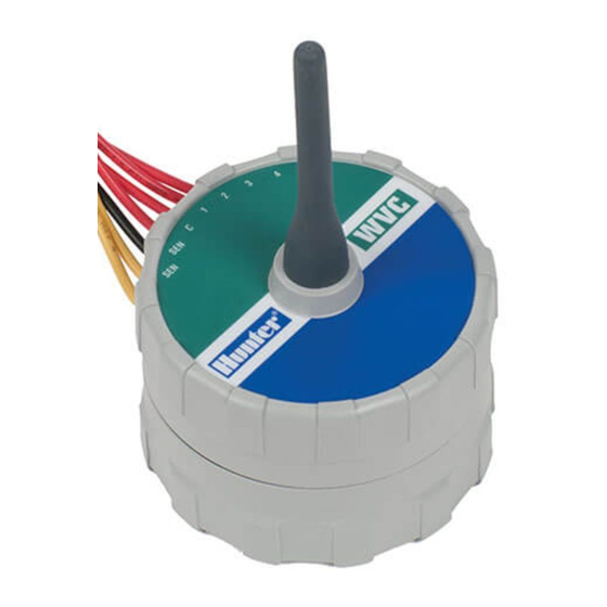
WVC ComponenTs ..................This.section.provides.a.brief.overview.of.some.of.the.com- 7.. Universal Mounting Adapter.–.Allows.for.alternate. ponents.of.the.WVC..Each.item.will.be.discussed.in.further. methods.of.mounting.the.WVC..It.can.be.used.to. detail.later,.however,.this.section.can.be.helpful.in.getting. mount.the.WVC.to.the.side.of.the.valve.box.or.on.a.½". acquainted.with.the.different.options.available. (13.mm).diameter.section.of.plastic.pipe. 8.. LED Indicator Light.–.Used.when.setting.the.WVC. 1.. WVC Body.–.The.WVC.controller.is.designed.to.be.dirt. address. tolerant,.waterproof,.and.submersible.to.12.feet.. 2.. External Antennae.–.Flexible.rubber.antennae.for.radio. communication. 3.. 9-Volt Battery Holder.–.The.WVC.is.designed.to.oper- ate.on.a.single.9-volt.alkaline.battery..The.battery.easily. snaps.into.the.battery.holder. 4.. Wires for DC Latching Solenoids.–.Leads.are.provided. for.wiring.DC.latching.solenoids..The.red.wires.are. -
Page 7: Installing.the.battery
3.. Make.sure.no.water.is.inside.the.battery.compartment.. Make.sure.that.the.seals.are.in.good.condition..Screw. NOTE: The WVC has non-volatile memory the.WVC.body.halves.together.to.seal.the.compartment. that retains all program information when the battery is removed or in the event the battery is drained. To install the battery: 1.. Unscrew.the.rear.half.of.the.WVC.body.to.gain.access. -
Page 8: Wiring.dc.latching.solenoids.to.the.wvc
WIrIng dC laTChIng solenoIds To The WVC ........Leads.are.provided.to.attach.a.Hunter.DC.latching. NOTE: The maximum recommended solenoid.or.other.two-wire,.low-voltage.latching.solenoids. distance from the WVC to any Hunter DC to.the.WVC..(Hunter.DC.latching.solenoid.part.#458200) latching solenoid is approximately 100 feet with 18 gauge wire. Long distances Hunter.DC.latching.solenoids.have.two.leads:.one.colored. between the WVC and the DC latching sole- black.and.the.other.red. -
Page 9: Radio.communication
CommunICaTIon ................Below Ground Installation All.programming.and.manual.operations.with.the.WVC.can. be.controlled.with.the.WVP..Actual.performance.varies. For.maximum.radio.range,.position.WVC.as. depending.upon.the.installation.and.the.surrounding.ter- high.as.possible.(see.figure.below). rain..The.WVP.can.send/retrieve.data.to/from.the.WVC.up. to.100.ft.with.the.WVC.installed.in.the.valve.box.below. ground.level..Radio.range.increases.when.the.WVC.is. installed.above.ground..(Refer.to.the.WVP.Owner’s.Manual. Minimize Clearance regarding.radio.communication). Good Not recommended... -
Page 10: Addressing.the.wvc.with.the.wvp
.then.start.over.from.step.4. To set the unique address on the WVC: NOTE: If no WVP communication takes place after the red light on the WVC comes 1.. Press.the.Transmit/Receive.button.on.the.WVP.to.enter. on, the WVC will turn this light back off the.communications.mode.(Lower.portion.of.display). (after 20 seconds) and revert back to the 2.. -
Page 11: Mounting.the.wvc.to.a.hunter.valve
The WVC To a hunTer ValVe ..........To mount the WVC to a valve (Figure 2): The.WVC.can.easily.be.mounted.on.any.Hunter.plastic. valve..A.special.designed.valve.mounting.clip.makes.instal- 1.. Unscrew.the.existing.solenoid.from.the.valve. lation.a.snap. 2.. Screw.the.WVC.latching.solenoid.into.the.valve.bonnet. NOTE: When mounting the WVC, position 3.. Attach.the.large.end.of.the.valve.mounting.clip.to.the. the antenna vertical and as high as pos- middle.of.the.WVC.body.(mounting.clip.supplied.with. -
Page 12: Alternate.mounting.methods
............A.universal.mounting.clip.and.mounting.adapter.are.also. 3.. Attach.the.WVC.to.the.mounting.clip.and.slide.it.on.the. provided.with.the.WVC..These.accessories.provide.for. end.of.the.mounting.adapter. alternate.methods.of.mounting.the.controller.either.to.the. Stake Mounting Method (Figure 4) side.of.the.valve.box.or.stake.mounted.within.the.valve.box. The.universal.mounting.adapter.can.also.be.used.to.stake. Valve Box Mounting Method (Figure 3) mount.the.WVC. 1.. Position.the.universal.mounting.adapter.on.the.side.of. 1.. Cut.a.section.of.½".(13mm).diameter.plastic.pipe. the.valve.box..Make.sure.that.the.bracket.is.positioned. 2.. Drive.the.pipe.into.the.ground.inside.the.valve.box.to. so.that.the.controller.is.as.high.up.in.the.valve.box. position.the.WVC.to.the.desired.height. as.possible,.but.does.not.interfere.with.the.top.of.the. valve.box.cover. 3.. Slip.the.universal.mounting.adapter.on.top.of.the.pipe. 2.. Drive.two.screws.to.secure.the.adapter.to.the.side.of. 4.. Attach.the.WVC.to.the.mounting.clip.and.slide.onto.the. -
Page 13: Connecting.a.weather.sensor
ConneCTIng a WeaTher sensor ............A.Hunter.Mini-Clik .rain.sensor.or.other.micro-switch.type. ® weather.sensor.can.be.connected.to.the.WVC..The.purpose. of.this.sensor.is.to.stop.watering.when.weather.conditions. dictate. To connect a weather sensor to the WVC: 1.. Cut.the.yellow.wire.loop.attached.to.the.WVC.at. approximately.the.middle.of.the.loop. 2.. Remove.approximately.½".(13mm).of.insulation.from. each.wire..Attach.each.wire.to.each.of.the.wires.of.the. weather.sensor. 3.. Secure.both.wire.connections.with.waterproof. connectors. programmIng The ConTroller ............The.WVC.is.easy.to.program.with.its.companion,.the.WVP. Wireless.Valve.Programmer..The.easy-to-understand.push. button.design.of.the.WVP.allows.you.to.step.through.the. process.of.programming.and.activating.manual.watering. with.the.press.of.a.button..Further.information.on.operating. the.WVP.can.be.found.in.your.WVP.Owner’s.Manual. -
Page 14: Specifications
..................... Operating Specifications Electrical Specifications •. Station.run.time:.0.to.4.hours.in.1-minute.increments •. Solenoids:.Operates.6.to.9-volt.DC.latching.solenoids •. Start.times:.9.per.day •. Battery:.Standard.9-volt.alkaline.battery.(not.included),. one.year.minimum.life..Battery.not.required.for.pro- •. Day.of.the.week.calendar gram.backup. •. Interval.watering •. Memory:.Non-volatile.for.program.data•. •. AM/PM.or.24-hour.clock.option Weather.sensor.compatible •. Start.time.stacking.for.each.station •. Frequency.of.operation:.. •. One.button.manual.start.and.advance 900.MHz.ISM.band.(U.S./Aust.),.868.MHz.(Europe) •. Programmable.rain.delay.for.1.to.7.days Dimensions WVC.–.3.25".D.x.5".H WVP.–.3".W.x.11.5".L.x.2".H... -
Page 15: Fcc.notice
....................... This.notice.applies.only.to.models.WVC-100,.WVC-200,.and.WVC-400. FCC ID: M3UWVC This.equipment.has.been.tested.and.found.to.comply.with.the.limits.for.class.B.digital.device,.pursuant.to.part.15.of.the. FCC.Rules..These.limits.are.designed.to.provide.reasonable.protection.against.harmful.interference.in.a.residential.instal- lation..This.equipment.generates,.uses.and.can.radiate.radio.frequency.energy.and.if.not.installed.and.used.in.accordance. with.the.instructions,.may.cause.harmful.interference.to.radio.communications..However,.there.is.no.guarantee.that. interference.will.not.occur.in.a.particular.installation..If.this.equipment.does.cause.harmful.interference.to.radio.or.televi- sion.reception,.which.can.be.determined.by.turning.the.equipment.off.and.on,.the.user.is.encouraged.to.try.to.correct.the. interference.by.one.or.more.of.the.following.measures: •. Reorient.or.relocate.the.receiving.antenna •. Increase.the.separation.between.the.equipment.and.the.antenna •. Consult.the.dealer.or.an.experienced.radio/TV.technician.for.help The.user.is.cautioned.that.changes.and.modifications.made.to.the.equipment.without.the.approval.of.the.manufacturer. could.void.the.user’s.authority.to.operate.this.equipment. -
Page 16: Industry.of.canada.notice
IndusTry of Canada noTICe ..............This.notice.applies.only.to.models.WVC-100,.WVC-200,.and.WVC-400. IC: 2772-WVC The.term.“IC:”.before.the.certification/registration.number.only.signifies.that.the.Industry.of.Canada.technical.specifica- tions.were.met. Operation.is.subject.to.the.following.two.conditions:.(1).this.device.may.not.cause.interference,.and.(2).this.device.must. accept.any.interference,.including.interference.that.may.cause.undesired.operation.of.the.device. Ce noTICe ......................CE Notice: this notice applies only to models WVC-100-E WVC-200-E and WVC-400-E. Important Notice: Low.power.RF.product.operating.in. 869.700-870.000MHz.band.for.indoor.or. outdoor.home.and.commercial.use. Member.states.in.the.EU. with.restrictive.use.for.this. product.are.crossed.out. Hunter Industries Incorporated • The Irrigation Innovators ©...