Advertisement
Table of Contents
- 1 Table of Contents
- 2 Introduction
- 3 Important Safety Information
- 4 Pack Contents Checklist
- 5 Dimensions
- 6 Wiring Diagram
- 7 Specifications
- 8 Installation Requirements
- 9 Installation
- 10 Commissioning
- 11 Operation
- 12 Maintenance
- 13 Fault Diagnosis
- 14 Spare Parts
- 15 Accessories
- 16 Notes
- Download this manual
Advertisement
Table of Contents

Related Manuals for Mira Zest 7.5


Summary of Contents for Mira Zest 7.5
- Page 1 ELECTRIC SHOWERS Installation Operation &B Maintenance Guide THESE INSTRUCTIONS ARE TO BE LEFT WITH THE USER back...
-
Page 2: Table Of Contents
Contents Page Introduction ..............3 Important Safety Information ............ 4 Pack Contents Checklist ............6 Dimensions ..............7 Wiring Diagram ..............8 Specifications ................8 Installation Requirements ............9 Installation ..............13 Commissioning ............... 15 Operation ................. 17 Maintenance ................21 Fault Diagnosis ............... -
Page 3: Introduction
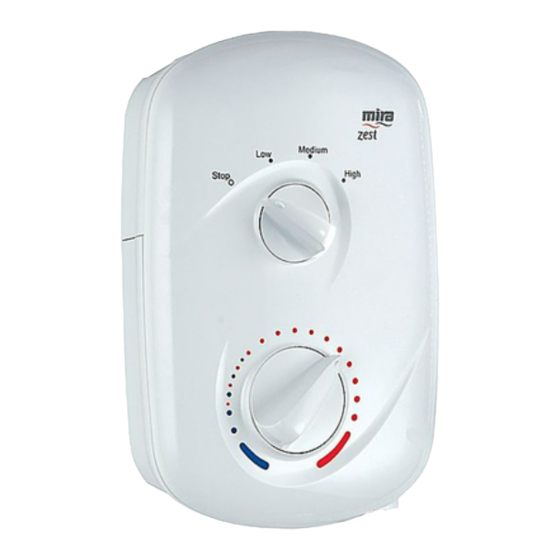
Appliances covered by this guide: Mira Zest 7.5 - A 7.5 kW 240 V AC (6.9 kW 230 V AC) heater with a Mira React adjustable spray handset. Supplied complete with flexible hose, adjustable clamp bracket assembly, slide bar and supports and hose retaining ring. Available in white finish. -
Page 4: Important Safety Information
1.7. DO NOT fit any form of outlet flow control as the outlet acts as a vent for the tank body. Only Mira recommended outlet fittings should be used. 1.8. There are no user serviceable components beneath the cover of the appliance. - Page 5 Caution! 2.1. Read all of these instructions and retain this guide for later use. 2.2. Pass on this guide in the event of change of ownership of the installation site. 2.3. Follow all warnings, cautions and instructions contained in this guide, and on or inside the appliance.
-
Page 6: Pack Contents Checklist
Pack Contents Checklist Tick the appropriate boxes to familiarize yourself with the part names and to confirm that the parts are included. 1. Mira Zest 7.5 or 8.5 kW 1 x Mira Zest 7.5 or 8.5 3 x Fixing Screws 3 x Wall Plugs 2. -
Page 7: Dimensions
Section Dimensions 297 mm 81 mm 202 mm... -
Page 8: Wiring Diagram
Minimum static pressure 0.2 bar to keep the flow valve closed. Electrical The appliance requires a 40 Amp fuse. The terminal block will not accept cable larger than 10 mm Standards and Approvals This Mira Zest complies with all the relevant directives for CE marking. -
Page 9: Installation Requirements
To avoid damage to the case when soldered fittings are used, pre-solder the pipework and fittings before connecting them to the inlet stub. 10. The appliance is fitted with a ½ " BSP male outlet thread, to accept a Mira shower hose. - Page 10 However, there will be occasions when the hose retaining ring will not provide a suitable solution. In these instances an outlet double checkvalve, e.g. the Mira DCV-H, must be fitted. The inclusion of the Mira DCV-H will increase the required supply pressure typically by 0.1 bar.
- Page 11 40A MCB type B and allowing for a 5 volt drop: Mira Zest 7.5 kW (240 V AC) at 240 V - 22 Metres Mira Zest 8.5 kW (240 V AC) at 240 V - 18 Metres A 30 mA residual current device (RCD) should be fitted.
- Page 12 Plumbing and Electrical Schematic Diagram...
-
Page 13: Installation
Installation Mira Zest 7.5 and 8.5 WARNING! Isolate the electrical and water supplies before proceeding with the installation of the appliance. Decide on a suitable position for the appliance (minimum distance of 200 mm from the ceiling to allow for cover fit and removal). The position of the appliance and the shower fittings must provide a minimum gap of 25 mm between the spill-over level of the shower tray/bath and the handset. - Page 14 Fixing Screw Electrical Supply Cable Do not fit the Mira Zest to the wall and tile up to the case. The Mira Zest must be fitted onto a finished flat and even wall surface (small...
-
Page 15: Commissioning
Commissioning Commissioning If you are unsure how electric showers work, please read through the Operation section before continuing. Make sure that the TOP control knob is in the 'STOP' position and that the electrical supply has been isolated. Turn the BOTTOM control knob fully anticlockwise to the full cold position. Turn the water supply fully on at the isolating valve, check that water is not leaking from the bottom of the case. - Page 16 High Position Medium Position Low Position Stop Position Select Shower Temperature By Rotating Clockwise As Necessary Full Cold Position...
-
Page 17: Operation
Operation Advice to Users Electric showers work by taking in cold water and passing it over the heating elements contained in the tank body of the shower. The showering temperature is adjusted by turning the temperature control knob, which varies the flow of cold water across the elements. The slower the rate of flow, the warmer the water and vice versa. - Page 18 The left-hand scale is temperature rise. (Temperature rise = Showering temperature minus the incoming cold water temperature.) Example: For the Mira Zest 8.5 kW on full power setting with an incoming water supply at 10°C and a showering temperature at 42°C, the temperature rise is 32°C. The flow...
- Page 19 Mira Zest 7.5 and 8.5 Read the section 'Important Safety Information' first. THE SPRAY PLATE HOLES MUST BE KEPT CLEAR. The spray plate should be regularly removed and cleaned in descalent. Lack of regular spray plate cleaning will lead to poor performance and cause early failure of the appliance.
-
Page 21: Maintenance
Maintenance General Read the section “Important Safety Information” first. Providing the shower has been correctly installed and is operated in accordance with the instructions contained in this guide, difficulties should not arise. If any maintenance is required then it must be carried out by a competent tradesperson the maintenance instructions are provided. - Page 22 Cover Retaining Screw Terminal Block Electrical Supply Cable Heater Tank Switching Assembly Microswitch Heater Tank and Flow Valve Retaining Screws Inlet Connector Flow Valve Assembly Clamp Bracket Clamp Bracket Inlet Supply Retaining Screws Pipe Flow Valve and Switch Assembly - Removal and Installation...
- Page 23 Heater Tank - Removal and Installation WARNING! Isolate the electrical and water supplies before removing the cover. Mains electricity connections are exposed when the cover is removed. Remove the three cover retaining screws, the cover and the service tunnel. Remove the hose from the outlet connector and loosen the connection to the inlet connector.
- Page 24 Thermal Switch Heater Tank Switching Terminal Assembly Block Microswitch Heater Tank and Flow Valve Clamp Bracket Flow Valve Retaining Screws Assembly Inlet Connector Clamp Bracket Retaining Screws Heater Tank - Removal Installation Thermal Switch - Removal and Installation WARNING! Isolate the electrical and water supplies before removing the cover. Mains electricity connections are exposed when the cover is removed.
- Page 25 Carefully pull the flow valve and switch assembly and the heater tank away from the case. Make sure that you ease the inlet connector off the inlet supply pipe. Remove the brown and red wires from one side of the thermal switch and the second brown wire from the other side of the thermal switch.
-
Page 26: Fault Diagnosis
Fault Diagnosis Fault Diagnosis WARNING! There are no user serviceable components beneath the cover of the appliance. Only a competent tradesperson should remove the cover. The trouble shooting information tabled below gives details on what you can do as a user without removing the cover should you encounter difficulties whilst operating the shower. - Page 27 Malfunction Cause Remedy (Continued) Handset sprayplate Remove and clean (Refer to blocked. Maintenance in the I,O& M guide for the fittings). Other outlets being used Ensure other outlets e.g. bath, whilst showering, causing washing machine or water pressure to drop dishwasher are not in use below minimum required whilst showering.
-
Page 28: Spare Parts
Spare Parts 1. Mira Zest Spare Parts List 416 15 Cover Assembly 416 36 Heater Tank - 7.5 kW 416 37 Heater Tank - 8.5 kW 416 38 Clamp Bracket 416 41 Thermal Switch 416 42 Cover Seal 416 43... - Page 29 2. Mira Zest Spare Parts Diagram 416 41 416 43 417 49 416 36 416 37 416 58 41746 417 48 872 78 416 42 417 47 416 63 416 47 416 38 416 15...
-
Page 30: Accessories
The inclusion of the Mira DCV-H will increase the required supply pressure typically by 0.1 bar. Available as an optional accessory from your Mira stockist. -
Page 31: Notes
Notes... - Page 32 (three years for the Mira Excel thermostatic range) from the date of purchase, provided that the product has If this does not resolve the difficulty, contact our Customer...