Grizzly Extreme Series Owner's Manual
14 inch extreme series bandsaw
Hide thumbs
Also See for Extreme Series:
- Owner's manual (92 pages) ,
- Manual (68 pages) ,
- Manual insert (32 pages)
Table of Contents
Advertisement
Quick Links
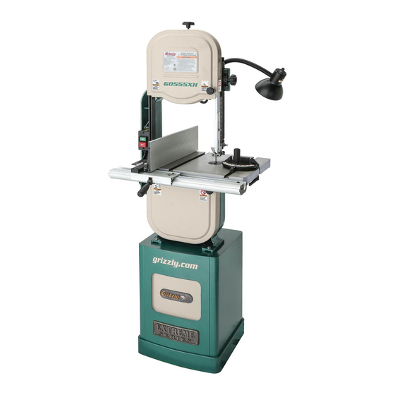
MODEL G0555X
14" EXTREME SERIES BANDSAW
OWNER'S MANUAL
(For models manufactured since 9/17)
COPYRIGHT © OCTOBER, 2006 BY GRIZZLY INDUSTRIAL, INC., REVISED AUGUST, 2018 (MN)
WARNING: NO PORTION OF THIS MANUAL MAY BE REPRODUCED IN ANY SHAPE
OR FORM WITHOUT THE WRITTEN APPROVAL OF GRIZZLY INDUSTRIAL, INC.
#TR8670 PRINTED IN TAIWAN
V4.08.18
Advertisement
Table of Contents

Related Manuals for Grizzly Extreme Series


Summary of Contents for Grizzly Extreme Series
- Page 1 OWNER'S MANUAL (For models manufactured since 9/17) COPYRIGHT © OCTOBER, 2006 BY GRIZZLY INDUSTRIAL, INC., REVISED AUGUST, 2018 (MN) WARNING: NO PORTION OF THIS MANUAL MAY BE REPRODUCED IN ANY SHAPE OR FORM WITHOUT THE WRITTEN APPROVAL OF GRIZZLY INDUSTRIAL, INC.
- Page 2 This manual provides critical safety instructions on the proper setup, operation, maintenance, and service of this machine/tool. Save this document, refer to it often, and use it to instruct other operators. Failure to read, understand and follow the instructions in this manual may result in fire or serious personal injury—including amputation, electrocution, or death.
-
Page 3: Table Of Contents
Table of Contents INTRODUCTION ..........2 SECTION 5: ACCESSORIES ......40 Contact Info............ 2 SECTION 6: MAINTENANCE ......42 Manual Accuracy ........... 2 Schedule ............42 Machine Data Sheet ........3 Cleaning ............42 Identification ........... 5 Lubricating ........... 42 SECTION 1: SAFETY ........ -
Page 4: Introduction
ID label. This will help us help you faster. tions, specifications, drawings, and photographs in this manual. Sometimes we make mistakes, but Grizzly Technical Support our policy of continuous improvement also means that sometimes the machine you receive is 1815 W. -
Page 5: Machine Data Sheet
MACHINE DATA SHEET Customer Service #: (570) 546-9663 · To Order Call: (800) 523-4777 · Fax #: (800) 438-5901 MODEL G0555X 14" EXTREME SERIES BANDSAW Product Dimensions: Weight................................236 lbs. Width (side-to-side) x Depth (front-to-back) x Height..............30 x 26 x 67-1/4 in. - Page 6 Main Specifications: Main Specifications Bandsaw Size............................14 in. Max Cutting Width (Left of Blade)......................13-1/2 in. Max Cutting Width (Left of Blade) w/Fence..................12-1/4 in. Max Cutting Height (Resaw Height)......................6 in. Blade Speeds............................. 3000 FPM Blade Information Standard Blade Length........................93-1/2 in. Blade Length Range......................
-
Page 7: Identification
Identification Blade Tension Knob Upper Wheel Blade Tension Guard Scale Guide Post Blade Tracking Lock Knob Knob Blade Quick Switch Release Lever Upper Blade Fence Guide Assembly Table Tilt Lock Knob Lower Blade Fence Lock Guide Assembly Handle Table Pin 4"... -
Page 8: Section 1: Safety
SECTION 1: SAFETY For Your Own Safety, Read Instruction Manual Before Operating This Machine The purpose of safety symbols is to attract your attention to possible hazardous conditions. This manual uses a series of symbols and signal words intended to convey the level of impor- tance of the safety messages. - Page 9 WEARING PROPER APPAREL. Do not wear FORCING MACHINERY. Do not force machine. clothing, apparel or jewelry that can become It will do the job safer and better at the rate for entangled in moving parts. Always tie back or which it was designed. cover long hair.
-
Page 10: Additional Safety For Bandsaws
Additional Safety for Bandsaws Serious cuts, amputation, or death can occur from contact with the moving saw blade during operation or if blade breakage occurs. To reduce this risk, anyone operating this machine MUST completely heed the hazards and warnings below. HAND PLACEMENT. -
Page 11: Section 2: Power Supply
SECTION 2: POWER SUPPLY Availability Circuit Information Before installing the machine, consider the avail- A power supply circuit includes all electrical ability and proximity of the required power supply equipment between the breaker box or fuse panel circuit. If an existing circuit does not meet the in the building and the machine. - Page 12 Grounding Requirements For 220V operation: The plug specified under “Circuit Requirements for 220V” on the previous This machine MUST be grounded. In the event page has a grounding prong that must be attached of certain malfunctions or breakdowns, grounding to the equipment-grounding wire on the included reduces the risk of electric shock by providing a power cord.
- Page 13 Extension Cords Voltage Conversion We do not recommend using an extension cord The voltage conversion MUST be performed by with this machine. If you must use an extension an electrician or qualified service personnel. cord, only use it if absolutely necessary and only on a temporary basis.
-
Page 14: Section 3: Setup
IMPORTANT: Save all packaging materials until you are completely satisfied with the machine and have resolved any issues between Grizzly or the shipping agent. You MUST have the original pack- aging to file a freight claim. It is also extremely Like all machinery there is potential danger helpful if you need to return your machine later. -
Page 15: Inventory
Inventory • Moving Plate (Resaw) ........ 1 • Lock Handle M8-1.25 x 44 (Resaw) ... 1 • Flat Washer 8mm (Resaw) ......1 • Hex Wrenches 3, 4, 5mm ....1 Each The following is a list of items shipped with your machine. -
Page 16: Hardware Recognition Chart
Hardware Recognition Chart USE THIS CHART TO MATCH UP HARDWARE DURING THE INVENTORY AND ASSEMBLY PROCESS. Flat Head Screw -14- G0555X (Mfd. Since 9/17) -
Page 17: Cleanup
Cleanup Gasoline and petroleum products have low flash The unpainted surfaces of your machine are points and can explode coated with a heavy-duty rust preventative that or cause fire if used to prevents corrosion during shipment and storage. clean machinery. Avoi d This rust preventative works extremely well, but it u sing t h e s e p r o d u c t s will take a little time to clean. -
Page 18: Site Considerations
Site Considerations Weight Load Physical Environment Refer to the Machine Data Sheet for the weight The physical environment where the machine is of your machine. Make sure that the surface upon operated is important for safe operation and lon- which the machine is placed will bear the weight gevity of machine components. -
Page 19: Assembly
Assembly The machine must be fully assembled before it can be operated. Before beginning the assembly process, refer to Needed for Setup and gather all listed items. To ensure the assembly process goes smoothly, first clean any parts that are cov- ered or coated in heavy-duty rust preventative (if Figure 7. - Page 20 Attach lever board to bandsaw body with (4) spacers and (4) M8-1.25 x 60 cap screws, as shown in Figure 10. Figure 12. Extension table installed. 12. Remove table insert from center of table and remove table pin from end of table slot. Figure 10.
- Page 21 17. Fasten front fence rail to front of bandsaw 22. Push fence handle down to lock fence in table with (2) M6-1 x 20 hex bolts, (2) 6mm position. lock washers, and (2) 6mm flat washers, as shown in Figure 14. 23.
-
Page 22: Dust Collection
Dust Collection Adjustment Overview The bandsaw is one of the most versatile wood- This machine creates a lot of wood chips/ working machines. However, it has multiple com- dust during operation. Breathing airborne ponents that must be properly adjusted for the dust on a regular basis can result in perma- best cutting results. - Page 23 Bandsaw wheels are either flat or crowned and Pull blade tension quick-release lever down both shapes track differently. This bandsaw has (as viewed from rear of machine) to apply crowned wheels. As the wheels spin, a properly tension to blade (see Figure 19). tracking blade naturally tracks at the center of the wheel (see Figure 18).
-
Page 24: Test Run
Spin upper wheel with one hand and slowly adjust tracking knob with other hand until blade consistently tracks in center of wheel. DO NOT start machine until all preceding setup instructions have been performed. Tighten wing nut to lock setting, then spin Operating an improperly set up machine upper wheel several times to confirm proper may result in malfunction or unexpect-... -
Page 25: Tensioning Blade
Tensioning Blade To tension bandsaw blade using flutter method: DISCONNECT MACHINE FROM POWER. A properly tensioned blade is essential for mak- ing accurate cuts, maximizing blade life, and Make sure blade is properly center tracking making other bandsaw adjustments. However, a (refer to Blade Tracking on Page 20 for properly tensioned blade will not compensate for instructions). -
Page 26: Adjusting Blade Support Bearings
Adjusting Blade The Deflection Method The deflection method is much more subjective Support Bearings than the flutter method. Each blade will deflect differently and every user will determine what "moderate pressure" means. The following are general guidelines for tensioning the blade with The support bearings are positioned behind the this method. -
Page 27: Adjusting Blade Guide Bearings
Adjusting Blade Loosen guide assembly lock bolt (see Figure 22) so that support bearing can be rotated Guide Bearings perpendicular to blade in next step. Rotate blade guide assembly until the face of support bearing is perpendicular to blade, as Properly adjusting the blade guides provides side- shown in Figure 23. -
Page 28: Adjusting Positive Stop
blade gullets Tighten cap screws to lock blade guides in position. Blade Guide Bearing Whenever changing a blade or adjusting Blade tension and tracking, the upper and lower blade guide bearings and blade guide bear- Gullets ings must be re-adjusted before cutting operations. -
Page 29: Setting Table Tilt Scale To 0
Leveling Extension Table The extension table must be level with the main table. It is important to keep the extension table at least ⁄ " away from the main table during leveling to allow the table room for tilting. To level extension table: Set table to 90°. -
Page 30: Aligning Table
Adjust two front set screws in lever board Loosen trunnion bolts that secure trunnions until extension table is even with main table. to table. Place a straightedge across the rear of the Place an accurate straightedge along the main table and extension table. blade. -
Page 31: Section 4: Operations
OMMEND that you read books, review industry trade magazines, or get formal training before beginning any projects. Regardless of the content in this section, Grizzly Industrial will not be held liable for accidents caused by lack of training. -29- G0555X (Mfd. Since 9/17) -
Page 32: General Overview
General Overview Disabling & Locking Switch The bandsaw is one of the most versatile wood cutting tools in the shop. It is capable of perform- The ON/OFF switch can be disabled and locked ing the following types of cuts: by inserting a padlock through the ON button, as shown. -
Page 33: Workpiece Inspection
Workpiece Setting Upper Blade Inspection Guide Height Some workpieces are not safe to cut or may When cutting, the blade guides must always require modification before they are safe to cut. be positioned so they just clear (no more than Before cutting, inspect all workpieces for the ⁄... -
Page 34: Adjusting Table Tilt
Adjusting Table Tilt Blade Selection The table can be tilted to make angled or beveled Selecting the right blade requires a knowledge cuts. A simple tilt scale is provided on the trun- of the various blade characteristics to match the nion for a quick gauge (see Figure 33). - Page 35 Blades will vary slightly even in the same length because of how they are welded. Refer to the Accessories section later in this manual for blade replacements from Grizzly. Blade Width Measured from the back of the blade to the tip of...
- Page 36 Tooth Pitch Blade Material Measured as TPI (teeth per inch), tooth pitch Bandsaw blades must meet two requirements: determines the number of teeth. More teeth per flexibility and hardness. The flexibility of a blade inch (fine pitch) will cut slower, but smoother; while allows it to travel on the wheel as a band, while fewer teeth per inch (coarse pitch) will cut rougher, hardness allows the teeth to cut and hold an...
-
Page 37: Blade Care & Break-In
Blade Care Blade Breakage & Break-In Many conditions may cause a bandsaw blade to break. Blade breakage is unavoidable in some Blade Care cases, since it is the natural result of the peculiar stresses that bandsaw blades are subjected to. A bandsaw blade is a thin piece of steel that is subjected to tremendous strain. -
Page 38: Changing Blade
Changing Blade Apply tension. If blade cannot be tensioned as described on Page 23, adjust the tension- er as described in Steps 4-6. If the tension is correct, go to Step 7. Note: The tensioner must be adjusted if you are using a different length of blade. -
Page 39: Scale Calibration
Scale Calibration Ripping You may need to recalibrate the fence scale after "Ripping" means cutting with the grain of the changing or adjusting the blade, or if the scale wood stock. For plywood and other processed is not producing accurate cuts. Recalibrate the wood, ripping simply means cutting down the fence scale by adjusting the hairline indicator on length of the workpiece. -
Page 40: Crosscutting
Crosscutting Resawing "Crosscutting" means cutting across the grain of "Resawing" (see Figure 44) means cutting the wood. For plywood and other processed wood, thickness of a board into two or more thinner crosscutting simply means cutting across the boards. The maximum board width that can be width of the workpiece. -
Page 41: Cutting Curves
Stacked Cuts When resawing thin pieces, a wandering blade (blade lead) can tear through the side One of the benefits of a bandsaw is its ability to of the workpiece, exposing your hands to cut multiple copies of a particular shape by stack- the blade teeth. -
Page 42: Section 5: Accessories
T28000—"Bear Crawl" Mobile Base We took years of input and months of testing and design to come out with the Grizzly “Bear Crawl” Mobile Base. Its 1200 lb. capacity, steel and rub- ber heavy-duty ball bearing wheels, and toe flip-... - Page 43 Mats measure 36" x 36" x ⁄ ". G0555X, G0555P, and G0580 bandsaws. Figure 52. H6572 Grease-Resistant Mat 3' x 3' Figure 50. T23070 Replacement Tires. ⁄ ". www.grizzly.com 1-800-523-4777 order online at or call -41- G0555X (Mfd. Since 9/17)
-
Page 44: Section 6: Maintenance
SECTION 6: MAINTENANCE Lubricating Always disconnect power to the machine before Protect the unpainted cast iron surfaces on the performing maintenance. table by wiping the table clean after every use— Failure to do this may this ensures moisture from wood dust does not result in serious person- remain on bare metal surfaces. -
Page 45: Section 7: Service
SECTION 7: SERVICE Review the troubleshooting procedures in this section if a problem develops with your machine. If you need replacement parts or additional help with a procedure, call our Technical Support. Note: Please gather the serial number and manufacture date of your machine before calling. Troubleshooting Motor &... - Page 46 Operating Machine Symptom Possible Cause Possible Solution Blade or teeth 1. Blade tension is too tight. 1. Reduce blade tension (Page 23). 2. Use correct blade for application (Page 32). break/crack. 2. Blade is incorrect for application. 3. Excessive feed rate/pressure. 3.
- Page 47 Operating Machine (Cont.) Symptom Possible Cause Possible Solution Blade tracks 1. Tracking not adjusted properly. 1. Adjust tracking (Page 20). 2. Adjust wheels to be coplanar (Page 50). incorrectly or 2. Wheels are not coplanar. comes off wheels. 3. Blade tension too loose. 3.
-
Page 48: Tensioning V-Belt
Tensioning V-Belt Tensioning V-Belt Items Needed Hex Wrench 6mm ..........1 To ensure optimum power transmission from the To properly tension V-belt: motor to the blade, V-belt must be in good condi- tion and operate under proper tension. DISCONNECT MACHINE FROM POWER! V-belt tension should be checked at least every Open lower wheel cover, and loosen motor month—more often if the bandsaw is used daily. -
Page 49: Replacing V-Belt
Replacing V-Belt Move body of motor so motor adjustment bolt slides to the right-hand side of adjustment slot. To ensure optimum power transmission from Pull belt off of motor pulley. motor to blade, V-belt must be in good condition and be properly tensioned. Unthread wheel mount bolt shown in Figure 55, and slide lower wheel off of bearing shaft. -
Page 50: Shimming Table
Shimming Table Correcting Blade Lead To ensure accuracy when cutting stacked "Blade Lead" means that the blade does not cut workpieces, the table should be 90˚ to the back of straight when using the fence or miter gauge (see the blade as shown in Figure 56. If the table is not Figure 57). -
Page 51: Calibrating Fence Scale
Calibrating Fence Clamp the board to the bandsaw table with- out moving it. Now slide the fence over to Scale the board so it barely touches one end of the board. Loosen the four cap screws on top of the You may need to recalibrate the fence scale after fence. -
Page 52: Wheel Alignment
Wheel Alignment Referring to Figure 60, check wheel alignment. Wheel alignment is important for optimal perfor- mance from your bandsaw. Wheels are properly aligned when they are parallel with each other and in the same plane or “coplanar” (see the illustra- tion in the figure to the right). - Page 53 Shimming a Wheel Remove blade. A wheel that is parallel with the other wheel, but Remove wheel to be shimmed. Place as is not coplanar, must be shimmed by the distance many shims as necessary to correct the gap that it is not in the same plane with the other measured in Step 3 onto the wheel shaft.
-
Page 54: Blade Tensioner
Blade Tensioner Loosen the set screws in both of the spacers indicated in Figure 63. Back the spacers away from the tension lever The blade tensioner may need to be reset for one crossbar shown in Figure 62. of the following reasons: Upper •... -
Page 55: Section 8: Wiring
Technical Support at (570) 546-9663. The photos and diagrams included in this section are best viewed in color. You can view these pages in color at www.grizzly.com. -53- G0555X (Mfd. Since 9/17) -
Page 56: Wiring Diagram
(Switches Viewed from Behind) 110V Wiring Diagram Lamp Switch Work Lamp (40-Watt Maximum) 120 VAC 5-15 Plug ON/OFF Switch (viewed from behind) Work Lamp (40 Watt Maximum) 5-15 Plug 110-120 VAC Ground Neutral Ground 110 VAC Motor at 110V-120V (prewired) 5-15 Plug Neutral Start... -
Page 57: Wiring Diagram
(Switch Viewed from 220V Wiring Diagram NOTICE To maintain CSA compliance when the machine is converted to Work Lamp 220V, the work lamp must be (40-Watt Maximum) disconnected from power and removed from the machine as instructed on Page 11. 120 VAC ON/OFF Switch 5-15 Plug... -
Page 58: Section 9: Parts
SECTION 9: PARTS Main 31 32 63 58 144 133 35-2 35-3 35-1 14V2 24 19 11V2 25V2 11V2-1 11V2-2 11V2-3 11V2-4 11V2-5 11V2-6 71 72 11V2-7 11V2-8 11V2-9 11V2-10 11V2-11 -56- G0555X (Mfd. Since 9/17) - Page 59 HEX BOLT M8-1.25 X 20 LH P0555X008 KEY 5 X 5 X 25 P0555X048 LOWER WHEEL GUARD P0555X009 FENDER WASHER 8MM P0555X049 GRIZZLY ROUND KNOB M8-1.25 P0555X010 CAP SCREW M8-1.25 X 16 P0555X050 INT TOOTH WASHER 8MM 11V2 P0555X011V2 MOTOR 1.5HP 1PH 110/220V V2.05.11 P0555X051 LATCH STUD M8-1.25 X 14...
- Page 60 Main Parts List (cont.) REF PART # DESCRIPTION REF PART # DESCRIPTION P0555X134 FLAT WASHER 8MM P0555X144 SPACER 8 X 20MM P0555X135 BUSHING P0555X150 LOWER LOCK COLLAR P0555X136 BUTTON HD CAP SCR M8-1.25 X 20 P0555X151 SET SCREW M5-.8 X 5 P0555X137 SPACER P0555X153...
-
Page 61: Table, Fence & Guides
Table, Fence & Guides 36V2 -59- G0555X (Mfd. Since 9/17) - Page 62 Table, Fence & Guides Parts List REF PART # DESCRIPTION REF PART # DESCRIPTION 36V2 P0555X036V2 LAMP ASSY W/POWER CORD V2.04.12 P0555X148 FLAT WASHER 6MM P0555X037 FLANGE SCREW M5-.8 X 8 P0555X149 LOCK WASHER 6MM P0555X079 UPPER BLADE GUIDE BRACKET P0555X155 CAP SCREW M6-1 X 25 P0555X080...
-
Page 63: Stand
REF PART # DESCRIPTION P0555X301 STAND P0555X311 DOOR P0555X302 TAP SCREW M3.5 X 8 P0555X312 DOOR LATCH ASSEMBLY P0555X303 EXTREME SERIES LOGO P0555X313 GRIZZLY LOGO PLATE P0555X304 HEX NUT M6-1 P0555X314 FLAT WASHER 10MM P0555X305 LOCK WASHER 6MM P0555X315 HEX NUT 3/8-16... -
Page 64: Labels & Cosmetics
Safety labels help reduce the risk of serious injury caused by machine hazards. If any label comes off or becomes unreadable, the owner of this machine MUST replace it in the original location before resuming operations. For replacements, contact (800) 523-4777 or www.grizzly.com. -62-... - Page 65 Would you recommend Grizzly Industrial to a friend? _____ Yes _____No Would you allow us to use your name as a reference for Grizzly customers in your area? Note: We never use names more than 3 times. _____ Yes _____No 10.
- Page 66 FOLD ALONG DOTTED LINE Place Stamp Here GRIZZLY INDUSTRIAL, INC. P.O. BOX 2069 BELLINGHAM, WA 98227-2069 FOLD ALONG DOTTED LINE Send a Grizzly Catalog to a friend: Name_______________________________ Street_______________________________ City______________State______Zip______ TAPE ALONG EDGES--PLEASE DO NOT STAPLE...
-
Page 67: Warranty And Returns
WARRANTY AND RETURNS Grizzly Industrial, Inc. warrants every product it sells for a period of 1 year to the original purchaser from the date of purchase. This warranty does not apply to defects due directly or indirectly to misuse, abuse, negligence, accidents, repairs or alterations or lack of maintenance.