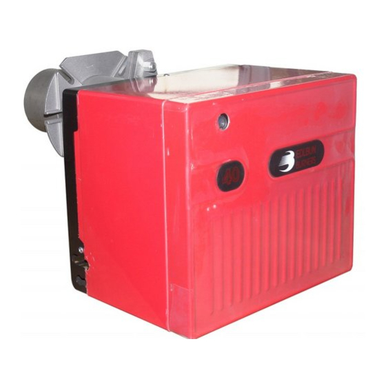
Riello FS10 Installation, Use And Maintenance Instructions
Forced draught gas burner
Hide thumbs
Also See for FS10:
- Installation, use and maintenance instructions (32 pages) ,
- Installation, use and maintenance instructions (88 pages) ,
- Installation, use and maintenance instructions (36 pages)
Summary of Contents for Riello FS10
- Page 1 Installation, use and maintenance instructions Forced draught gas burner One stage operation CODE MODEL TYPE 20033121 FS10 564T31 20039281 (2) - 10/2011...
-
Page 3: Table Of Contents
CONTENTS BURNER DESCRIPTION ... WORKING ..... . . Burner equipment ....4.1 Combustion adjustment. -
Page 4: Technical Data
TECHNICAL DATA 2.1 TECHNICAL DATA Thermal power 42 – 116 kW 36,000 – 100,000 kcal/h Net heat value: 8 – 12 kWh/Nm 7,000 – 10,340 kcal/Nm (Family 2) Natural gas Pressure: min. 16 mbar max. 100 mbar ± Electrical supply Single phase, 230 V 50Hz Motor... -
Page 5: Installation
TEST BOILER The working field has been defined according to EN 676 standard. COMMERCIAL BOILERS The burner-boiler matching is assured if the boiler conforms to EN 303 and the combustion chamber dimensions are similar to those shown in the diagram EN 676. For applications where the boiler does not conform to EN 303, or where the combustion chamber is much smaller than the dimensions given in EN 676, please consult the manufacturers. -
Page 6: Probe-Electrode Positioning
3.2 PROBE - ELECTRODE POSITIONING Ignition electrode Ionization probe Diffuser Probe Electrode D5104 – WARNING 3.3 GAS FEEDING LINE D5069 1 – Gas supply pipe 2 – Manual cock (supplied by the installer) 3 – Gas pressure gauge (supplied by the installer) 4 –... -
Page 7: Electrical Wiring
ELECTRICAL WIRING All the installation, maintenance and disassembly operations must be carried out with the electricity sup- ply disconnected. WARNING The burner requires periodic maintenance carried out by a qualified and authorised technician in con- formity with legislation and local standards. DANGER ATTENTION: Do not swap neutral and phase over, follow the diagram shown carefully and carry out a good earth connection. -
Page 8: Device
4.2 COMBUSTION HEAD SETTING Loose the screw (A), move the elbow (B) so that the rear plate of the coupling (C) coincides with the set point. Tighten the screw (A). Example: kcal/h The burner is installed on a 81 kW boiler D5258 with an efficiency of 90%, the burner 100,000... -
Page 9: Air Pressure Switch
IONIZATION CURRENT The minimum current necessary for the control box operation is 3 µA. The burner normally supplies a higher current value, so that no check is needed. However, if you want to measure the ionization current, you must open the connector fitted to the red wire and insert a microammeter. Connector Terminal board of control-box... -
Page 10: Burner Start-Up Cycle
4.6 BURNER START-UP CYCLE S8271 AL - Error message (alarm) Start command (switching on by «R») BV - Fuel valve B-B´ Interval for establishment of flame FS - Flame signal Operating position of burner reached GP - Gas pressure switch C-D Burner operation (generation of heat) LP - Air pressure switch Controlled shutdown by «R»... -
Page 11: Resetting The Control Box And Using Diagnostics
4.8 RESETTING THE CONTROL BOX AND USING DIAGNOSTICS The control box features a diagnostics function through which any causes of malfunctioning are easily identi- fied (indicator: RED LED). To use this function, you must wait at least 10 seconds once it has entered the safety condition (lock-out), and then press the reset button. -
Page 12: To Avoid Burnout Or Bad Combustion Of The Burner
The sequence of pulses issued by the control box identifies the possible types of malfunction, which are listed in the table below. SIGNAL PROBABLE CAUSE The flame does not stabilise at the end of the safety time: – faulty ionisation probe; –... -
Page 13: Faults / Solutions
FAULTS / SOLUTIONS Here below you can find some causes and the possible solutions for some problems that could cause a fail- ure to start or a bad working of the burner. A fault usually makes the lock-out lamp light which is situated inside the reset button of the control box (9, fig. - Page 14 Signal Problem Possible cause Recommended remedy 10 blinks The burner does not 32 - Incorrect electrical wiring ... . . Check switch on, and the lockout appears The burner goes into 33 - Defective control box .
- Page 15 STANDARD ELECTRICAL WIRING INDEX Indication of references Functional layout Indication of references /1.A1 Sheet no Co-ordinates 20039281...
- Page 16 20039281...
-
Page 17: Control Box
KEY TO ELECTRICAL LAYOUT – Control box – Suppresor – Working signal – Capacitor – Connector – Hour counter – Switch – Ionisation probe – Valve assembly – Air pressure switch PGMin– Minimum gas pressure switch – Main disconnecting swich –... - Page 20 RIELLO S.p.A. I-37045 Legnago (VR) Tel.: +39.0442.630111 http:// www.riello.it http:// www.rielloburners.com Subject to modifications...


