Table of Contents
Advertisement
PRECAUTIONS
Please follow these precautions:
To prevent fire or shock hazard, do not expose the unit to rain or
moisture.
To prevent electrical shock, do not open the cabinet. Refer to qualified
personnel for service only.
Do not use the unit continuously for more than 24 hours with camera
auto focus on. It may cause damage to the camera lens.
Be careful not to spill water or other liquids onto the unit, or allow
combustible or metallic objects to get inside the cabinet.
Unplug the visulizer from the wall outlet when it is not being
used for a long period of time.
Clean the cabinet with a soft cloth lightly moistened with a mild
detergent solution.
Clean the lens carefully with an air spray or soft dry cloth to avoid
scratching it.
When the lamps flash or become dark, they should be replaced with
new ones.
Avoid switching arm lights and back light frequently.
Remove the camera lens cap before power the unit on.
CONTACTS:
QOMO HITEVISION, LLC
Toll Free: 1-866-990QOMO
E-Mail: info@qomo.com
Web: www.qomo.com
1
Advertisement
Table of Contents

Related Manuals for Qomo QD700


Summary of Contents for Qomo QD700
- Page 1 When the lamps flash or become dark, they should be replaced with new ones. Avoid switching arm lights and back light frequently. Remove the camera lens cap before power the unit on. CONTACTS: QOMO HITEVISION, LLC Toll Free: 1-866-990QOMO E-Mail: info@qomo.com Web: www.qomo.com...
-
Page 2: Table Of Contents
CONNECTIONS..................6 BASIC PREPARATIONS ................7 OUTPUT MODE AND VERTICAL FREQUENCY (60Hz) ......11 PAL/NTSC VIDEO OUTPUTS..............11 INSTALLING QOMO VISUALIZER SOFTWARE ........11 USB CAPTURE FOR MAC COMPUTER..........13 WORKING ON THE STAGE ..............13 WORKING OUTSIDE THE STAGE............13 LIGHT..................... 14 ADJUSTING IMAGE SIZE .............. -
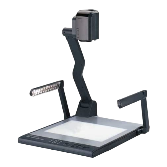
Page 3: Parts Identification
USB PORT..................... 19 CONTROLLING THE VISUALIZER FROM A COMPUTER ....19 VIDEO DISPLAY AND CAPTURE............20 CONTROLLING PROJECTOR WITH VISUALIZER ......20 FOLDING THE UNIT................24 SPECIFICATIONS.................. 26 TECHNICAL SUPPORT................. 28 PARTS IDENTIFICATION Camera Camera stand Arm lights Button instruction Connectors Back light Connectors... -
Page 4: Button Instruction
Split (Image Split function) Ppw (Control the projector On/Standby) Pin (Projector input signal selection) (Move the image up/down) CCD/PC1/PC2 (CCD/RGB input signal selection) S-VIDEO /VIDEO (Video input signal selection) LAMP (Control the arm lights and back light) AUTO (To auto adjust white balance and auto focus) (Increase and decrease the magnification) Remarks: Frz, Title, D./S. -
Page 5: Remote Control
REMOTE CONTROL LAMP POWER SAVE SPLIT B&W TITLE D./S. PROJECTOR TEXT INPUT TELE VOL+ AUTO NEAR VOL- VIDEO WIDE BLUE BRIGHT SCROLL POWER (Control the visualizer On/Off) SAVE (Save captured images) RECALL (Display saved images) EXIT (Exit RECALL mode) LAMP (Control the arm lights and back light) FREEZE (Freeze the image) NEG (Display film negatives) MIRROR (V-Reverse the image) -
Page 6: Connections
(Increase and decrease the magnification) TELE/ IDE FAR/NEAR (Focus near or far) VOL+/VOL- (Increase or decrease the volume) CCD/PC1/PC2 (CCD/RGB input signal selection) VIDEO (Video input signal selection) RED +/- (Increase/decrease the red hue) BLUE +/- (Increase/decrease the blue hue) BRIGHT +/- (Increase/decrease the brightness) (Move the image up/down) SCROLL /... -
Page 7: Basic Preparations
BASIC PREPARATIONS 1. Use one hand holds the base of the visualizer, use the other hand carefully lift up the camera stand of the unit. 2. Open the arm lights and rotate the camera head until they are in proper positions. Arm lights 3. - Page 8 Rear Panel S-VIDEO AUDIO VIDEO S-VIDEO AUDIO VIDEO AUDIO AUDIO IN PROJECTOR OUT -COMPUTER- IN OUT-12V- IN RGB Input RS232 Cable Screen Projector Side Panel PROJECTOR RGB IN AUDIO IN RS232 Connect visualizer’s PROJECTOR port to the RGB IN port of the projector port with the RGB cable provided together the visualizer.
- Page 9 Rear Panel To the Monitor AUDIO VIDEO S-VIDEO AUDIO VIDEO S-VIDEO PROJECTOR OUT -COMPUTER- IN OUT-12V- IN AUDIO AUDIO IN USB Connector RGB Output RS232 Cable Computer PROJECTOR RGB IN AUDIO IN RS232 Side Panel Note: You can connect a laptop computer to the RGB IN port of side panel with a RGB cable.
- Page 10 Step 5: Connect to the second video equipment with video input. Video Cable Video out Audio out Video equipment Rear Panel AUDIO VIDEO S-VIDEO VIDEO S-VIDEO OUT-12V- IN AUDIO AUDIO AUDIO IN -COMPUTER- PROJECTOR Projector Color monitor Video in Step 6: Connections for external control from the computer. Side Panel PROJECTOR MIC RGB IN...
-
Page 11: Output Mode And Vertical Frequency (60Hz)
Media Player or its own player. Insert the CD-ROM that comes with your visualizer into the CD-ROM drive. If Autorun is enabled on your system, then the QOMO Software Setup window will be displayed automatically as below. A. Click the Install Code-Writing Program button to install Code-Writing Program. - Page 12 that captures images in the AVI or JPG format. D. Click the Install USB Driver button to install the driver designed for the visualizer and will be used by the Capture Program. E. After the installation is finished, then click the Exit button to exit the Software Setup window.
-
Page 13: Usb Capture For Mac Computer
USB CAPTURE FOR MAC COMPUTER Copy the folder “Mac Driver” into Mac hard disk, open the folder and double click “Empia 1.0.0b2.zip”, the “setup” file appears. Following the screen notice, click “Next” and finish installation. Notes: 1. Please connect the Mac computer and visualizer when installing driver. -
Page 14: Light
LIGHT The arm lights are on when the power is on. Each time you press the “LAMP” buttons, the lighting changes as below. The arm lights turn on The back light turns on All the lights turn off ADJUSTING IMAGE SIZE In order to reduce or enlarge the image size displayed on the screen, press the “... -
Page 15: Focusing
FOCUSING When the visualizer is turned on the focus automatically adjusts to the stage, it is not necessary to readjust the focus if you are only working with flat materials (text, photos, etc.). Only 3D objects require a focus adjustment. Press the “AUTO”... -
Page 16: Text/Image Mode
TEXT/IMAGE MODE Press the “TEXT” button to switch between image/text modes. To display a text file, switch to the text mode to get a clearer text effect. (On the remote control) COLOR AND B&W MODE SWITCH Press “B&W” once to enter the Black & White mode; Press again to return to the Color mode. -
Page 17: Projector Inputs Selection
PROJECTOR INPUTS SELECTION When the projector is connected to several input sources, use the “Pin” button to switch signal inputs of the projector. (On the remote control, press the “PROJECTOR INPUT” button) Note: Please connect the projector RS232 cable between the projector and the visualizer first. -
Page 18: Title Function
(On the remote control) INFRARED REMOTE CONTROL The QD700’s remote control can control the camera from different angels. Please note that an infrared remote control can only be used up to a certain distance to the unit. Objects situated between the visualizer and the infrared remote control and a weak battery may interfere with the reception. -
Page 19: Usb Port
part of the image. Press the “ ” button to scroll the image up to display the lower part of the image. USB PORT The USB port can be used to transfer still images from the visualizer to a computer. No additional computer hardware is required. In this way, the visualizer can be used as a 3-D scanner for your computer. -
Page 20: Video Display And Capture
VIDEO DISPLAY AND CAPTURE You can capture and control images on the visualizer from a computer connected with a USB connector. Click [Start] -> [Program] -> [VideoCap] -> “VideoCapx.xx” (x.xx is to open the software. software’s version) A. Static Images Snap Click “Capture”—>“Capture Frame”, input the file name in dialog box, or you can click icon on the toolbar, then input file name in dialog... - Page 21 1. Connect the visualizer to the projector with the RGB、VIDEO、 S-VIDEO cables. 2. Connect the RS232 cable to the computer’s connector. The visualizer’s RS232 port is located on its right side. 3. After completion of the connection, turn on the visualizer,click [start] ->...
- Page 22 The input format of projector’s control code is as follows: a. If the data is in the numerical value format, please input data directly, block them off with comma, do not distinguish lowercase and uppercase. For example: the “POWER ON” code in Hitachi projector manual is : BE EF 03 06 00 BA D2...
- Page 23 port first). Then use buttons on the operation panel to control the projector. The visualizer provides a 6-pin to 9-pin RS232 cable. If this cable does not match to your projector’s RS232 port, an additional RS232 cable is needed. This additional RS232 cable can be made based on the pin location of the projector’s RS232 control port.
-
Page 24: Folding The Unit
the Baud Rate and Parity based on the projector’s Baud rate, then click “Open”. Click the projector control buttons on the visualizer’s operating panel to check if the control code that the program received is the same as the sending code. If the receiving code is same to the sending code, the input codes are correct. - Page 25 2. Carefully Fold the camera stand down to the front panel. Cautions: a. Don’t lay the unit down flat. b. Don’t try to stand it on its rear or sides.
-
Page 26: Specifications
c. Don’t try to pick up this unit by pulling the camera stand. NOT THIS WAY SPECIFICATIONS Color system NTSC or PAL system Pickup device 1/4″professional CCD Resolution XGA (1024 x 768), SVGA(800 x 600) Total Pixels 470,000 RGB Output Pixels 780,000 22 x optical zoom, 10 x digital zoom Lens... - Page 27 Audio: Mini jack 2 MIC: Mini jack 1 PC Audio: Mini jack 2 RGB: DB15FLC 2 RGB DB15FLC 2 C-Video: RCA jack 1 Output connectors S-Video: 4 pin mini Din 1 Audio: Mini jack 1 Operating system Windows 2000/XP USB connector 30 frames/sec RS-232 connector 9-pin, D-Sub, male/6-pin PS/2...
-
Page 28: Technical Support
Product serial number(s) Detailed and specific questions Online Technical support is also available online at QOMO’s web site at www.qomo.com. You can enter your questions and concerns through our online form. Or you can email us at info@qomo.com. Copyrights © 2004 QOMO Hitevision, LLC. All Rights Reserved.