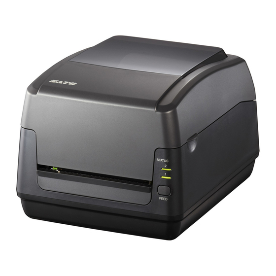
SATO WS408TT Service Manual
Ws4 tt series
Hide thumbs
Also See for WS408TT:
- Technical manual (135 pages) ,
- Programming reference manual (226 pages) ,
- Operator's manual (102 pages)
Summary of Contents for SATO WS408TT
- Page 1 WS4 TT Series Printer Service Manual WS408TT / WS412TT WS4-TT-r02-17-02-17SM © 2017 SATO Corporation. All rights reserved.
-
Page 2: Table Of Contents
Contents 1 Introduction ..........................1 1.1 About This Manual ......................1 1.2 Warnings and Cautions ..................... 1 2 Maintenance ..........................2 2.1 Print Head Maintenance ....................2 3 Spare Parts List ......................... 3 4 Spare Parts Removal and Assembly ..................9 4.1 Top Cover ........................... -
Page 3: Introduction
About This Manual This service manual gives the information necessary for you to adjust and repair the WS4 TT printer. This service manual is written only for SATO authorized service personnel. The information in this manual is confidential to general users. -
Page 4: Maintenance
2 Maintenance Print Head Maintenance Warning: Always turn off the printer before cleaning. It is essential to keep print head clean if you want the best printing quality. We strongly recommend that you clean the print head when loading a new media roll. If the printer is operated in critical environment or the print quality declines, you need to clean the print head more frequently. -
Page 5: Spare Parts List
3 Spare Parts List Parts Number Description Picture WT205-001 PRINT HEAD (203dpi) WS408TT WT301-001 PRINT HEAD (300dpi) WS412TT 59-WT2A1-001 RIBBON-ADAPTERS-WS4TT 59-WT2A2-001 ASSY-PLATEN-WS4TT 59-WT2A3-001 ASSY-MAIN-PCBA-WS4-LAN (USB + LAN) 59-WT2A3-011 ASSY-MAIN-PCBA-WS4-STD (USB + LAN + RS232C) - Page 6 Parts Number Description Picture 59-WT2A4-001 ASSY-SENSORS-WS4TT 59-WT2A5-001 ASSY-MOTOR-WS4TT 59-WT2A6-001 SW-PSU-WS4TT-N 59-WT2A7-001 ASSY-PANEL-PCBA-WS4TT 59-WT2A8-001 HRNS-PRINT-HEAD-WS4TT 59-WT2A9-001 GEARS-WS4TT...
- Page 7 Parts Number Description Picture 59-WT2B2-001 SPRING-PRINT-HEAD-WS4TT 59-WT2B3-001 ASSY-TOP-COVER-WS4TT 59-WT2B4-001 MID-COVER-WS4TT 59-WT2B5-001 PRINTER-FRAME-WS4TT 59-WT2B6-001 ASSY-MEDIA-HLDR-R-WS4TT 59-WT2B7-001 ASSY-MEDIA-HLDR-L-WS4TT...
- Page 8 Parts Number Description Picture 59-WT2B8-001 BOTTOM-COVER-WS4TT-LAN 59-WT2B8-011 BOTTOM-COVER-WS4TT-STD 59-WT2B9-001 FRONT-COVER-WS4TT 59-WT2C2-001 ASSY-MEDIA-ROLLER-WS4TT 59-WT2C4-001 ASSY-GUIDE-ROLLER-WS4TT 59-WT2A6-011 SW-PSU-WS4TT-N-EX1...
- Page 9 Parts Number Description Picture 59-WT2C3-001 POWER-CORD-WS4TT-CN 59-WT2C3-061 POWER-CORD-WS4TT-EX1 59-WT2C3-031 POWER-CORD-WS4TT-EU (For EU, VN-NESIA and KR Area Code) 59-WT2C3-011 POWER-CORD-WS4TT-UK (For UK, SP and MY Area Code) 59-WT2C3-021 POWER-CORD-WS4TT-TH 59-WT2C3-041 POWER-CORD-WS4TT-IND...
- Page 10 Parts Number Description Picture 59-WT2C3-051 POWER-CORD-WS4TT-PA 59-WT2C3-071 POWER-CORD-WS4TT-BR 59-WT2C3-081 POWER-CORD-WS4TT-AR...
-
Page 11: Spare Parts Removal And Assembly
4 Spare Parts Removal and Assembly Top Cover Open the top cover. (Figure A-1) Take off the top cover and push the right latch in orange and lifting the TPH module upward. (Figure A-2) Then we can see the TPH and the platen roller in orange. -
Page 13: Platen Roller And
Platen Roller and Front Cover. Platen Roller 1. From upside of the printer, use screwdriver to loosen 6 screws which are marked in orange. Then we can take off the front cover. (Figure B-1) 2. When we face to the printer ,taking out the left and right bushing which are marked in orange, then we could take out the platen roller. -
Page 14: Main Board And Bottom Cover
Main Board and Bottom Cover After taking off top, mid and front cover, we can see Main Board connect with cable and Bottom Cover from backside of the printer. (Figure C-1) Disconnect all cables from MB then lift up and separate the whole printer module. -
Page 16: Mid Cover
Mid Cover From upside of the printer, use screwdriver to loosen 6 screws which are marked in orange. Then we can take out the front cover first. (Figure D-1) Secondly, from broadside to pull the mid cover upward and take it out. (Figure D-2) Warning: ... -
Page 17: Motor
Motor Separate the whole printer module with main board and disconnect the cable which is marked in orange.(Figure E-1) Using screwdriver to loosen 3 screws which are marked in orange. (Figure E-2) Then we can take the motor out as shown in Figure E-3. -
Page 19: Sensors
Sensors Transmissive Sensor 1. After taking out the whole printer module and separating the motor with it ,we can see the Transmissive Sensor and Reflective Sensor which are marked in orange. (Figure F-1) Reflective Sensor 1. After taking out the Reflective Film, then we can see the Reflective Sensor which is marked in orange. -
Page 20: Tph
Push and pull down TPH itself in order to separate with the latch which is marked in orange. (Figure G-1) Pull the TPH out and loosen 2 screws which are marked in orange. ( Figure G-2) Disconnect the two cables which are marked in orange to take the TPH out. -
Page 21: Printer Status And Interface Connection
Printer Status and Interface Connection Printer Status Indication Status lights can help you check printer’s condition. The following tables show the blinking speed of status lights and the conditions they indicate. Symbol Blinking Blinking Interval Speed Fast 0.5 Second Slow 2 Seconds * LED2 + *LED1 Slow... -
Page 22: Printer Connector Pin Assignment
Printer Connector Pin Assignment Type A Type B Signal Description VBUS Differential data signaling pair - Differential data signaling pair + Ground Ground Ethernet 1 2 3 4 5 6 7 8 Signal Transmit+ Transmit- Receive+ Reserved Reserved Receive- Reserved Reserved... - Page 23 RS232C Signal Description Provide 5V Power Receive Transmit No Connection Ground Pull High RTS NC Request to Send Clear to Send Pull High Host (DB9) Printer (DB9) Signal Description Description Signal Carrier Detect Provide 5V Power Receive Receive Transmit Transmit Data Terminal Ready No Connection Ground...


