
Related Manuals for Texas Instruments S6350


Summary of Contents for Texas Instruments S6350
- Page 1 HF Reader System Series 6000 S6350 Multi-Protocol Reader Modules: RI-STU-TRDC-01 & 02 Reference Guide 11-06-21-700 September 2001 A TEXAS INSTRUMENTS TECHNOLOGY...
- Page 2 S6350 Reader Reference Guide Second Edition - September 2001 This is the second edition of this manual. It describes the S6350 Reader (formerly published as the Series 5000 RI-STU-TRDC-00 Reader Reference Guide). It contains a description of the following reader modules:...
- Page 3 Preface Read This First About This Manual This reference guide for the S6350 High-frequency (13.56Mhz) Reader is designed for use by TI customers who are engineers experienced with RFID Systems and Radio Frequency Identification Devices (RFID). Firmware Device Name Hardware Configuration...
- Page 4 September 2001 S6350 Reader Reference Guide If You Need Assistance Application Centers are located in Europe, North and South America, the Far East and Australia to provide direct engineering support. For more information, please contact your nearest TI-RFID Systems Sales and Application Center.
-
Page 5: Table Of Contents
September 2001 S6350 Reader Reference Guide Document Overview Chapter 1: Introduction......................6 1.1 Description....................7 1.1.1 Programming Interface................7 1.2 Summary of Chapters and Appendixes ............7 Chapter 2: Harware Description..................8 2.1 General Specification...................9 2.1.1 Functional Requirements................9 2.1.2 Power Supply ..................9 2.1.3 Output Power ..................9 2.1.4 Required Antenna Parameters.............. -
Page 6: Chapter 1: Introduction
September 2001 S6350 Reader Reference Guide Chapter 1 Introduction Topic Page 1.1 Description....................7 1.1.1 Programming Interface................7 1.2 Summary of Chapters and Appendixes ............7... -
Page 7: Description
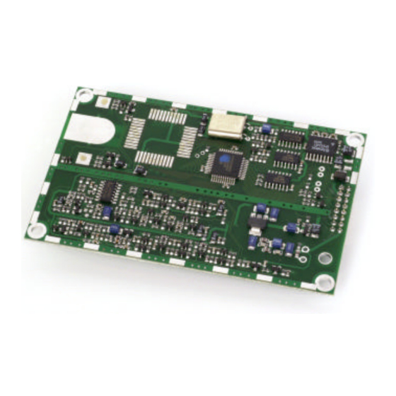
Figure 1: S6350 High Frequency Reader 1.1.1 Programming Interface The S6350 Reader is designed to operate as a part of a host-based reader system, which essentially relegates the reader to be a slave to the host. Host-to-Tag-it reader serial communications are accomplished within data packets whereby communications from the host to the reader are known as requests, and replies from the reader to the host are known as responses. -
Page 8: Chapter 2: Harware Description
Chapter 2 Hardware Description Topic Page 2.1 General Specification...................9 2.1.1 Functional Requirements................9 2.1.2 Power Supply ..................9 2.1.3 Output Power ..................9 2.1.4 Required Antenna Parameters.............. 10 2.1.5 Input / output pins (CN1 pins 3 and 4) ........... 10 2.1.6 Baseband receiver ................11 2.1.7 Connector Details ................ -
Page 9: General Specification
S6350 Reader Reference Guide 2.1 General Specification This chapter describes the electrical and mechanical specifications of the S6350 RI-STU-TRDC-02 reader. Operating at a frequency of 13.56 MHz, this low profile, low power device is designed to be easily integrated into many systems as an embedded device. All reader I/O is accomplished through the use of a 16-pin header connector (labeled as CN1), to include all communication, which is asynchronous RS232 as controlled by a host system. -
Page 10: Required Antenna Parameters
Loaded Q 10 < Q < 30 Note: As no standard antenna is provided by Texas Instruments for the S6350 reader, the noted required antenna parameters must be closely followed by the integrator for the reader to operate properly. 2.1.5 Input / output pins (CN1 pins 3 and 4) Pins 3 and 4 on CN1 may be configured by software commands to read a logic level input or to switch an external load to ground (no pull-up is provided). -
Page 11: Baseband Receiver
September 2001 S6350 Reader Reference Guide 2.1.6 Baseband receiver Minimum data pulse width Maximum data pulse width 500uS Typical settling time 50uS from the first transition Note: The receiver extracts the mean level of the incoming data stream as a reference. This takes approximately 50uS; therefore the data output of the receiver is not valid until after this time. -
Page 12: Ri-Stu-Trdc-01 (Cn1) Pin Assignments
September 2001 S6350 Reader Reference Guide 2.1.9 RI-STU-TRDC-01 (CN1) Pin Assignments Figure 3: 16-pin Right-Angle Header Connector (CN1) Component Side... -
Page 13: Ri-Stu-Trdc-02 (Cn1) Pin Assignments
September 2001 S6350 Reader Reference Guide 2.1.10 RI-STU-TRDC-02 (CN1) Pin Assignments Figure 4: 16-pin Header Connector (CN1) viewed from component side. COMPONENT SIDE... -
Page 14: Mechanical Specifications
September 2001 S6350 Reader Reference Guide 2.2 Mechanical Specifications 2.2.1 RI-STU-TRDC-01 with 16-pin Right-Angle Connector Figure 5: Note: All dimensions are in metric... -
Page 15: Ri-Stu-Trdc-02 With 16-Pin Straight Header Connector
September 2001 S6350 Reader Reference Guide 2.2.2 RI-STU-TRDC-02 with 16-pin Straight Header Connector Figure 6: Note: All dimensions are in inches COMPONENT SIDE... -
Page 16: Chapter 3: Reader Protocol
Chapter 3 Reader Protocol Topic Page 3.1 Serial Protocol Definition ................17 3.1.1 Request Packet Format (Host to Reader)..........17 3.1.2 Response Packet Format (Reader to Host)..........18 3.1.3 Command Flags Request..............18 3.1.4 Command Flags Response ..............19 3.1.5 BCC....................19 3.1.6 Example Request Packet .............. -
Page 17: Serial Protocol Definition
3.1 Serial Protocol Definition The S6350 reader accepts and sends data at RS232 levels, 57600 baud, 8 data bits, 1 start bit, 1 stop bit and no parity. The data packet from the host to the reader is known as the request and the reply from the reader to the host as the response. -
Page 18: Response Packet Format (Reader To Host)
September 2001 S6350 Reader Reference Guide 3.1.2 Response Packet Format (Reader to Host) Field Name Field Size 1 byte Field Value Purpose Start of Frame Field Name Length Field Size 2 byte LSB first Field Value Packet dependent Purpose Describes the length of the whole packet including SOF... -
Page 19: Command Flags Response
September 2001 S6350 Reader Reference Guide 3.1.4 Command Flags Response The command flags in the response packet report the actions of the reader. The meanings of the bits are defined below. Bits 0-3 Reserved for future use. Bit 4 Error flag. If this flag is set the command was unsuccessful and the data section of the response packet contains the error code. -
Page 20: Command Definitions
September 2001 S6350 Reader Reference Guide 3.2 Command Definitions 3.2.1 Tag-it™ HF Command Definitions Command Function (Tag-it HF) Command Code Read Single Non-addressed & Addressed Block Write Single Non-addressed & Addressed Block Lock Single Non-addressed & Addressed Block Read Transponder Details... - Page 21 September 2001 S6350 Reader Reference Guide Example Response packet 01 0A 00 00 00 00 03 00 08 F7 Successful write. Lock Block Command (04 Locks a single block of data in a Tag-it transponder. If the address flag is set, the address forms the first part of the data section, followed by a single byte containing the number of the block to lock.
- Page 22 September 2001 S6350 Reader Reference Guide Example Read blocks 0, 3 & 4 of a Tag-it transponder (data byte = 00011001 = 19 Request packet 01 0A 00 00 00 00 0F 19 1D E2 The data section of the response packet contains:...
-
Page 23: Miscellaneous Commands
September 2001 S6350 Reader Reference Guide 3.2.2 Miscellaneous Commands Command Function Command Code Initiate FLASH Loader Command Send Data to FLASH Command Reader Version Command Read Inputs Command Write Reader Outputs Command RF Carrier on/off Command Initiate FLASH Loader Command (D0 This command is used to initialize and transfer control to the FLASH loader software. - Page 24 September 2001 S6350 Reader Reference Guide Reader Type Example Response packet 01 0C 00 00 00 00 F0 40 01 07 BB 44 The version number is 1.4 The reader type response can be defined as follows: Type 07 = Indicates that the reader has been successfully loaded with the noted application firmware version number (in this example, version 1.4).
- Page 25 September 2001 S6350 Reader Reference Guide The response packet is similar to the request packet with the data section containing ‘00 ’ for a successful write operation. Example Response packet 01 0A 00 00 00 00 F2 00 F9 06 Write successful.
-
Page 26: Iso/Iec Fcd 15693 Part 3 Transmission Protocol
15693-3 commands are not provided within this document, but are covered within the ISO/IEC IS 15693-3:2001(E) Anti-Collision and Transmission Protocol document. The ISO 15693-3 commands that are specifically applicable to the S6350 Reader are defined within the following table. 3.2.3.1 ISO/IEC 15693-3 Command Codes... - Page 27 The structure of the ISO 15693 Command Data Request is contained within the Data section of the ISO Command Data, bytes 1 - n. Specific to the S6350 reader, the ISO 15693 SOF, CRC16 and EOF fields must not be included in the message data packet.
- Page 28 September 2001 S6350 Reader Reference Guide Request Packet Format Standard reader Request Packet Format (See Section 3.1) Header Packet Node Command Command ISO Command Checksum Length Address Flag Data Config. Data Byte ‘01 ’ Flags ‘60 ’ Data Byte 1...
- Page 29 September 2001 S6350 Reader Reference Guide Response Packet Format Standard reader Response Packet Format (See Section 3.1) Header Packet Node Response Command ISO Response Checksum Length Address Flags Data Data bytes ‘01 ’ Flags ‘60 ’ Byte 1 Byte 2 0 - ‘m’...
-
Page 30: Mandatory Commands
September 2001 S6350 Reader Reference Guide 3.2.3.3 Mandatory Commands The data packet from the host to the reader is known as the request and the reply from the reader to the host as the response. The host is always the primary station and initiates all communication sequences. - Page 31 September 2001 S6350 Reader Reference Guide Valid Data & Collision Flags Valid Data Flags: This 16-bit field corresponds to whether valid data was received in the 16 possible Time Slots. Bits 0 to 7 of the LSB respectively correspond to Time Slots 1 to 8, while bits 0 to 7 of the MSB correspond to Time Slots 9 to 16 respectively.
-
Page 32: Optional Commands
September 2001 S6350 Reader Reference Guide ISO Stay Quiet Request Command Packet: Command Code (02 Upon receipt of the Stay Quiet command, the ISO tag will enter the quiet state and will not initiate a response. Note: There is no response to the Stay Quiet command. - Page 33 September 2001 S6350 Reader Reference Guide ISO Read Single Block Response Packet Header Packet Node Response Command ISO Response Data Check Length Address Flags Data ‘01 ’ 2 bytes 2 bytes 1 byte ‘60 ’ bytes 2 bytes 0 - m...
- Page 34 September 2001 S6350 Reader Reference Guide ISO Write Single Block: Command Code (21 ISO Write Single Block Request Command Packet Header Packet Node ISO Command Data Check- Length Address Flag Config. Data Byte ‘01 ’ 2 bytes 2 bytes ‘60 ’...
- Page 35 September 2001 S6350 Reader Reference Guide ISO Lock Block: Command Code (22 ISO Lock Block Request Command Packet Header Packet Node ISO Command Data Check- Length Address Flag Config. Byte Data ‘01 ’ 2 bytes 2 bytes ‘60 ’ Byte 0...
- Page 36 September 2001 S6350 Reader Reference Guide ISO Read Multiple Blocks: Command Code (23 ISO Read Multiple Blocks Request Command Packet Header Packet Node ISO Command Data Check- Length Address Flag Config. Data Byte ‘01 ’ 2 bytes 2 bytes ‘60 ’...
- Page 37 September 2001 S6350 Reader Reference Guide ISO Write AFI: Command Code (27 ISO Write AFI Request Command Packet Header Packet Node ISO Command Data Chec Length Address Flag k-sum Config. Byte Data ‘01 ’ 2 bytes 2 bytes ‘60 ’...
- Page 38 September 2001 S6350 Reader Reference Guide ISO Lock AFI: Command Code (28 ISO Lock AFI Request Command Packet Header Packet Node ISO Command Data Check- Length Address Flag Config. Data Byte ‘01 ’ 2 bytes 2 bytes ‘60 ’ Byte 0...
- Page 39 September 2001 S6350 Reader Reference Guide ISO Write DSFID: Command Code (29 ISO Write DSFID Request Command Packet Header Packet Node ISO Command Data Check- Length Address Flag Config. Byte Data ‘01 ’ 2 bytes 2 bytes ‘60 ’ Byte 0...
- Page 40 September 2001 S6350 Reader Reference Guide ISO Lock DSFID: Command Code (2A ISO Lock DSFID Request Command Packet Header Packet Node ISO Command Data Check- Length Address Flag Config. Data Byte ‘01 ’ 2 bytes 2 bytes ‘60 ’ Byte 0...
- Page 41 September 2001 S6350 Reader Reference Guide ISO Get Multiple Block Security Status: Command Code (2C ISO Get Multiple Block Security Status Request Command Packet Header Packet Node ISO Command Data Check- Length Address Flag Config. Data Byte ‘01 ’ 2 bytes 2 bytes ‘60...
-
Page 42: Chapter 4: Regulatory And Warranty Notices
Chapter 4 Regulatory and Warranty Notices Topic Page 4.1 FCC Conformity..................43 4.2 ETSI Conformity ..................43 4.3 CE Conformity................... 43 4.4 Warranty and Liability ................43... -
Page 43: Fcc Conformity
European community. 4.4 Warranty and Liability The "General Conditions of Sale and Delivery" of Texas Instruments Incorporated or a TI subsidiary apply. Warranty and liability claims for defect products, injuries to persons and property damages are void if they are the result of one or more of the following causes: §... -
Page 44: Appendix B: Downloading Data To Flash Memory
Appendix A Downloading Data to FLASH Memory The S 6350 Reader FLASH memory contains two areas: the application area for the Reader application firmware and a boot-loader area for the boot-loader firmware. The boot-loader memory is factory locked. After a reset the boot-loader firmware runs the following sequence: •... -
Page 45: Appendix B: Error Codes
Appendix B Error Codes Code number Meaning Transponder not found Command not supported Packet BCC invalid Packet flags invalid for command General write failure Write failure due to locked block Transponder does not support function Undefined error...