Table of Contents
Advertisement
Quick Links
This User's Guide discusses how to properly operate and configure the DP83869EVM. For best layout
practices, schematic files, and Bill of Materials, see the associated support documents.
SNLU237 – September 2018
Submit Documentation Feedback
DP83869EVM User's Guide
Copyright © 2018, Texas Instruments Incorporated
User's Guide
SNLU237 – September 2018
DP83869EVM User's Guide
1
Advertisement
Table of Contents

Related Manuals for Texas Instruments DP83869EVM


Summary of Contents for Texas Instruments DP83869EVM
- Page 1 User's Guide SNLU237 – September 2018 DP83869EVM User's Guide This User’s Guide discusses how to properly operate and configure the DP83869EVM. For best layout practices, schematic files, and Bill of Materials, see the associated support documents. SNLU237 – September 2018...
-
Page 2: Table Of Contents
100M Media Convertor Strap Table ....................1000M Media Strap Table ....................4-Pin Dip Switch Modes Trademarks All trademarks are the property of their respective owners. DP83869EVM User's Guide SNLU237 – September 2018 Submit Documentation Feedback Copyright © 2018, Texas Instruments Incorporated... -
Page 3: Definitions
Reduced Media Independent Interface RGMII Reduced Gigabit Media Independent Interface SGMII Serial Gigabit Media Independent Interface VDDA Analog Core Supply Rail VDDIO Digital Supply Rail Pulldown Pullup SNLU237 – September 2018 DP83869EVM User's Guide Submit Documentation Feedback Copyright © 2018, Texas Instruments Incorporated... -
Page 4: Introduction
(direct contact). This device interfaces to the MAC layer through Reduced GMII (RGMII) and SGMII. Integrated Termination Impedance on RGMII helps reduce system BOM. The DP83869EVM will demonstrate all features of DP83869. The EVM will support Copper Ethernet protocols like 10BASE-Te, 100BASE-TX, and 1000BASE-T. -
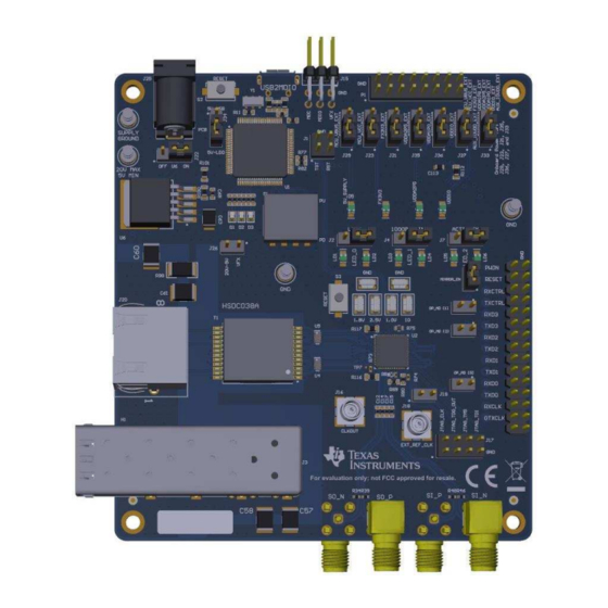
Page 5: Dp83869Evm - Top Side
Introduction www.ti.com Figure 1. DP83869EVM – Top Side SNLU237 – September 2018 DP83869EVM User's Guide Submit Documentation Feedback Copyright © 2018, Texas Instruments Incorporated... -
Page 6: Dp83869Evm - Bottom Side
Introduction www.ti.com Figure 2. DP83869EVM – Bottom Side DP83869EVM User's Guide SNLU237 – September 2018 Submit Documentation Feedback Copyright © 2018, Texas Instruments Incorporated... -
Page 7: Onboard Power Supply Connection
Windows 7 (or above) PC, MSP430 drivers and USB2MDIO software utility will have to be installed. The USB2MDIO software can be used for accessing registers. 2.2.3.1 MSP430 Driver Install the latest MSP430 drive from this website: http://software- dl.ti.com/msp430/msp430_public_sw/mcu/msp430/MSP430_FET_Drivers/latest/index_FDS.html. SNLU237 – September 2018 DP83869EVM User's Guide Submit Documentation Feedback Copyright © 2018, Texas Instruments Incorporated... - Page 8 In case the onboard MSP430 cannot be used due to some reason, MDIO and MDC pins are also broken out on the J15 connector. Customers can connect a MSP430 launchpad or their own MDIO-MDC utility on J15 to access the PHY registers. DP83869EVM User's Guide SNLU237 – September 2018 Submit Documentation Feedback Copyright © 2018, Texas Instruments Incorporated...
-
Page 9: Board Setup Details
MDIO Fiber IO Transceiver LED ACT LED SPEED SGMII LED LINK Diodes Strap Resistors Magnetics/ Capacitive JTAG Coupling RJ-45 Figure 5. DP83869EVM Block Diagram SNLU237 – September 2018 DP83869EVM User's Guide Submit Documentation Feedback Copyright © 2018, Texas Instruments Incorporated... -
Page 10: Evm Applications
Board Setup Details www.ti.com EVM High-Level Summary The DP83869EVM supports SMI through J2 using pin 26 for MDIO and 28 for MDC. These pins can be connected to an MSP430 Launchpad, which can be used for USB-2-MDIO control. Table 2. EVM Applications... -
Page 11: Configuration Options
Table 4. 2 Level Straps STRAP VALUE MODE 1 MODE 2 Resistor PU (kΩ) 2.49 Open Resistor PD (kΩ) Open 2.49 Figure 6. EVM Strap Jumpers SNLU237 – September 2018 DP83869EVM User's Guide Submit Documentation Feedback Copyright © 2018, Texas Instruments Incorporated... -
Page 12: Phy Strap Table
Auto MDI-X Auto-negotiation, 1000/100 advertised, Auto MDI-X Auto-negotiation, 100/10 advertised, Auto-MDI-X Reserved (JTAG for boundary LED_1 ANEGSEL_0 scan) Forced 1000M, master, MDI mode DP83869EVM User's Guide SNLU237 – September 2018 Submit Documentation Feedback Copyright © 2018, Texas Instruments Incorporated... -
Page 13: 1000Base-X Strap Table
NAME ANEGSEL_ ANEGSEL_ ANEGSEL_ LED_1 Copper : Auto-negotiation ( 100/10 Advertised), Auto MDIX ANEGSEL_ LED_2 Copper : Auto Negotiation ( 100 Advertised), Auto MDIX SNLU237 – September 2018 DP83869EVM User's Guide Submit Documentation Feedback Copyright © 2018, Texas Instruments Incorporated... -
Page 14: 1000M Media Strap Table
25-MHz crystal, 25-MHz CMOS oscillator, and the External clock from the SMB connector. A 50-Ω Coax cable with a SMB connector should be used for providing clock input from external sources. DP83869EVM User's Guide SNLU237 – September 2018 Submit Documentation Feedback Copyright © 2018, Texas Instruments Incorporated... -
Page 15: Onboard Clock
Figure 8. External Clock Input Switch Configuration Options The DP83869EVM includes a 4-pin dip switch (S3), which can be used for various test modes and feature displays. Some of the switch settings can also be used with the USB-2-MDIO GUI for additional control. - Page 16 LOAD = the string 'LOAD' indicates to the MC to add a register to the list • AAAA = Four character Register Address to read data from in hex form (that is, Read register 0x133h, set AAAA = 0133) DP83869EVM User's Guide SNLU237 – September 2018 Submit Documentation Feedback Copyright © 2018, Texas Instruments Incorporated...
- Page 17 NOTE: When the read loop is stopped, the list of registers to read is cleared. SNLU237 – September 2018 DP83869EVM User's Guide Submit Documentation Feedback Copyright © 2018, Texas Instruments Incorporated...
-
Page 18: Schematics
Schematics www.ti.com Schematics Figure 9. Schematic Page 1 DP83869EVM User's Guide SNLU237 – September 2018 Submit Documentation Feedback Copyright © 2018, Texas Instruments Incorporated... -
Page 19: Schematic
Schematics www.ti.com Figure 10. Schematic Page 2 SNLU237 – September 2018 DP83869EVM User's Guide Submit Documentation Feedback Copyright © 2018, Texas Instruments Incorporated... -
Page 20: Schematic
Schematics www.ti.com Figure 11. Schematic Page 3 DP83869EVM User's Guide SNLU237 – September 2018 Submit Documentation Feedback Copyright © 2018, Texas Instruments Incorporated... -
Page 21: Schematic
Schematics www.ti.com Figure 12. Schematic Page 4 SNLU237 – September 2018 DP83869EVM User's Guide Submit Documentation Feedback Copyright © 2018, Texas Instruments Incorporated... -
Page 22: Schematic
Schematics www.ti.com Figure 13. Schematic Page 5 DP83869EVM User's Guide SNLU237 – September 2018 Submit Documentation Feedback Copyright © 2018, Texas Instruments Incorporated... -
Page 23: Schematic
Schematics www.ti.com Figure 14. Schematic Page 6 SNLU237 – September 2018 DP83869EVM User's Guide Submit Documentation Feedback Copyright © 2018, Texas Instruments Incorporated... - Page 24 DP83869EVM User's Guide SNLU237 – September 2018 Submit Documentation Feedback...
- Page 25 TI products. TI’s provision of these resources does not expand or otherwise alter TI’s applicable warranties or warranty disclaimers for TI products. Mailing Address: Texas Instruments, Post Office Box 655303, Dallas, Texas 75265 Copyright © 2018, Texas Instruments Incorporated SNLU237 –...
- Page 26 TI products. TI’s provision of these resources does not expand or otherwise alter TI’s applicable warranties or warranty disclaimers for TI products. Mailing Address: Texas Instruments, Post Office Box 655303, Dallas, Texas 75265 Copyright © 2018, Texas Instruments Incorporated...