
Related Manuals for Radio Shack 2200813


Summary of Contents for Radio Shack 2200813
- Page 1 2200813 User’s Guide 29-Range Digital Multimeter Thank you for purchasing your 29-Range Digital Multimeter from RadioShack. Please read this user’s guide before installing, setting up, and using your new multimeter.
-
Page 2: Table Of Contents
Contents Checking Diodes ........14 Checking Batteries .........16 Package Contents ........3 Additional Information .......18 Features ............3 Replacing the Fuse .........18 Care and Service ........3 Auto Power Off ........19 Safety Precautions ........4 Testing the Display .........19 Special Panel Markings ......7 Specifications..........20 Install the Batteries ........8 Limited Warranty ........22 Connect the Test Leads ......8 Basic Operation ........9... -
Page 3: Package Contents
Package Contents • 29-Range Digital Multimeter • Test Leads (2) • Spare Fuse (in the case) • User’s Guide Features • Measures voltage, current and resistance • Auto-ranging with manual-ranging override • Diode test Care and Service • Keep your meter dry and clean. If it gets wet or dirty, wipe it dry or clean immediately with a cloth lightly dampened with water. -
Page 4: Safety Precautions
Safety Precautions • Do not use the meter if you are unfamiliar with electric circuits and testing procedures. • To avoid electric shock, disconnect both test leads from the circuit under testing before you replace the batteries and fuse. • Do not operate the meter until the batteries are properly installed and the back cover and battery compartment cover are in place and secured. - Page 5 • The test leads (black and red) supplied with your meter are rated for 1000 volts but do not try to measure any voltage greater than 600 volts DC/600 volts RMS AC. Use only test leads of the same rating as the meter. • Your multimeter is designed primarily to measure household AC voltages. Because of the dangers inherent in measuring three-phase circuits, WE STRONGLY RECOMMEND YOU DO NOT USE THIS METER TO MEASURE 3-PHASE, LINE-TO-LINE VOLTAGE. If you still want to, put on protective clothing – a face shield and fireproof gloves and upper body protection is required before measuring.
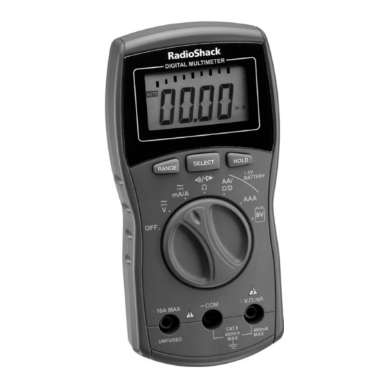
- Page 6 AUTO – Auto range mode. Bar Graph Display – 8 segments represent units for the selected function. Range – Press to select ranges. SELECT – Toggle measurement options within a function. HOLD – Press to hold all indications on the display. Function/Power dial Turn the meter on/off or select the type of measurement: • V –...
-
Page 7: Special Panel Markings
Special Panel Markings The maximum voltage that this meter can measure is 600V RMS AC or 600V 600V DC. To avoid electric shock and damage to the meter, do not connect the two input terminals (-COM and +V.Ω.mA) to any source that exceeds 600 volts with respect to ground. The maximum current that this meter can measure at this jack is 400mA DC or 400mA Caution: RISK OF ELECTRIC SHOCK! Refer to the complete operating instructions. Caution: Be extremely careful when taking high-voltage measurements. DO NOT TOUCH TERMINALS OR TEST LEAD ENDS. CAT II This equipment is rated for installation category II (3600 VA max.). 10A MAX. The maximum current you can measure at this jack is 10 amps DC/AC. This UNFUSED jack is not fuse-protected. -
Page 8: Install The Batteries
Install the Batteries Before installing batteries, turn off the multimeter and disconnect the test leads. Install three AAA batteries (not included), matching the polarity symbols (+ and -) marked inside. When appears, replace the batteries. • Dispose of batteries promptly and properly. Do not burn or bury them. • Use only fresh batteries of the required size and type. • If you do not plan to use the meter for a month or more, remove the batteries. Batteries can leak chemicals that can damage electronic parts. Connect the Test Leads 1. -
Page 9: Basic Operation
Basic Operation Range Display 400 mV ddd.d mV Selecting Ranges d.ddd V 40 V dd.dd V Set the meter to a measurement range; the unit of measure 400 V ddd.d V appears on the display. For example, mV appears in the 400 mV range. 600 V ddd V 40 mA dd.dd mA Note the position of the decimal: 400 mA ddd.d mA • If 0.000V appears, the meter is set to measure less than d.ddd A 4 volts. 10 A dd.dd A • If 000 V appears, the meter is set to measure up to 600... -
Page 10: Measuring Dc/Ac Voltage
Caution: • If you are measuring voltage or current when OF (overflow) appears, immediately disconnect the test leads from the circuit. • When measuring high-voltage circuits, do not position both test leads at once. Connect the black test lead first to the circuit’s neutral or ground lead. Then, using one hand, probe for voltages with the other test lead. This helps prevent accidentally touching a hot wire. Measuring DC/AC Voltage DO NOT try to measure voltages above 600 V DC/AC (RMS). 1. Set the function dial to V . 2. -
Page 11: Measuring Ac Voltage Riding On A Dc Source Bias
Measuring AC Voltage Riding on a DC Source Bias Warning: To avoid injury or damage to your meter, never try to measure an AC voltage on a DC source bias where the peak AC voltage exceeds 100V with respect to earth ground. 1. Set the function dial to V (DC voltage). Measure the DC voltage first to ensure that it does not exceed 100V. 2. Disconnect power from the circuit. 3. Press SELECT (AC mode). appears. -
Page 12: Measuring Dc/Ac Current
Measuring DC/AC Current 1. Disconnect power from the circuit and discharge all capacitors. 2. Rotate the function dial to mA/A . 3. Press SELECT to select DC or AC. appears for AC current measurement. 4. Break the circuit and connect the black test lead to one of the two connection points. 5. -
Page 13: Measuring Resistance
Measuring Resistance 1. Disconnect power from the circuit and discharge all capacitors. 2. Rotate the function dial to Ω . 3. Repeatedly press SELECT to select Ω, KΩ, or MΩ. 4. Connect the black test lead to one component lead. 5. -
Page 14: Checking Continuity
Checking Continuity You can check for shorted or open electrical circuits. 1. Disconnect power from the circuit and discharge all capacitors. 2. Rotate the function dial to Ω . 3. Repeatedly press SELECT until appears. 4. Connect the black test lead to one end of the circuit and the red lead to the other end. • Open appears if the circuit resistance is greater than about 50 ±10 ohms (meaning the circuit is not shorted). - Page 15 3. Press SELECT until appears. 4. Connect the black test lead to the cathode or a component pin. 5. Connect the red test lead to the anode or the other component pin, or remove one of the leads of the component from its circuit and touch the test leads across the component.
-
Page 16: Checking Batteries
Checking Batteries The meter can accurately check the following batteries under designated load conditions: • 1.5V C • 1.5V D • 1.5V AA • 1.5V AAA • 9V batteries. 1. Rotate the function dial to your desired setting. 2. Connect the black test lead to the battery’s negative (–) terminal 3. Connect the red test lead to the battery’s positive (+) terminal. • If you connect the test leads in reverse polarity, – appears on the left side of the display. Use this table to determine the battery’s charge. - Page 17 Battery Range Display Action < 0.010 volts No value appears. < 0.10 volts Replace the battery. < 1 volt Voltage and Bad appear. < 6 volts 1 – 1.1 volts AAA/AA/C/D 6 - 6.6 volts The battery is good. 1.1 – 1.5 volts Voltage and Good appear. 6.6 - 9 volts > 1.5 volts The battery is full. > 9 volts > 2 volts .OF appears > 11 volts...
-
Page 18: Additional Information
Additional Information Replacing the Fuse If the meter does not operate or “FUSE Bad” Fuse appears on the display, you might need to Installed replace the fuse. Use the supplied spare fuse or a 5 × 20mm, 500mA, 250V Cooper Bussmann S501 series fuse or equivalent sand filled ceramic fuse. 1. Turn off the meter and disconnect the test leads. 2. Use a Phillips screwdriver to open the back cover of the meter. -
Page 19: Auto Power Off
Auto Power Off Your meter conserves power by automatically turning off about 30 minutes after the last time you changed a setting (even if you are taking measurements). The meter short beeps several times and long beeps once about 1 minute, then turns off. Press any button or select another function to turn it on. To set the meter so that it does not turn off automatically, press and hold HOLD and SELECT at the same time, as you turn on the meter. PLoc appears. When you release HOLD and SELECT. -
Page 20: Specifications
Specifications DC VOLTS (Maximum Measurement: 600V) 400mV ....................± 0.5% of Reading, ±4 in Last Digit 4V – 40V – 400V ..................± 0.8% of Reading, ±4 in Last Digit 600V ....................... ± 1.0% of Reading, ±4 in Last Digit AC VOLTS (600 V RMS Maximum at 50/60Hz, Average responds, RMS calibrated, DC Coupled) 400mV, 40V – 400V – 600V ..............± 1.2% of Reading, ±5 in Last Digit 4V ......................± 0.8% of Reading, ±5 in Last Digit DC CURRENT (Maximum Measurement: 10A) 40mA – 400mA ..................± 1.2% of Reading, ±4 in Last Digit 4A – 10A ....................± 1.5% of Reading, ±4 in Last Digit AC CURRENT (Average responds, RMS calibrated, 10A maximum, DC coupled) 40mA – 400mA ..................± 1.5% of Reading, ±4 in Last Digit 4A – 10A ....................± 2.0% of Reading, ±4 in Last Digit RESISTANCE 400Ω – 4k – 40kΩ – 400kΩ – 4.0MΩ ..........± 1.2% of Reading, ±4 in Last Digit 40MΩ... - Page 21 CONTINUITY BEEPER Continuity (short) ........................... <50 ±10 Ω Open ............................... >50 ±10 Ω Open Circuit ............................ <1.6 Volts Short Circuit Current .........................<1.0 mA GENERAL Maximum Common Mode Voltage ..................600V DC/AC Range Up Detect Value ..................Overflow (>4000 Counts) Range Down Detect Value ......................380 Counts Power Source ........................3 × AAA batteries Operating Temperature ................... 32°F to 104°F (0°C to 40°C) Storage Temperature ..................-4°F to 140°F (-20°C to 60°C) Humidity ................................Maximum Relative Humidity 80% for temperatures up to 87.8°F (31°C), decreasing linearity to 50% relative humidity at 104°F (40°C) Pollution Degree ............................2 Altitude ........................
-
Page 22: Limited Warranty
FCC Information This equipment has been tested and found to comply with the limits for a Class B digital device, pursuant to Part 15 of the FCC Rules. These limits are designed to provide reasonable protection against harmful interference in a residential installation. This equipment generates, uses, and can radiate radio frequency energy and, if not installed and used in accordance with the instructions, may cause harmful interference to radio communications. - Page 23 damage; (e) transportation, shipping or insurance costs; (f) costs of product removal, installation, set-up service, adjustment or reinstallation; and (g) claims by persons other than the original purchaser. Should a problem occur that is covered by this warranty, take the product and the RadioShack sales receipt as proof of purchase date to any RadioShack store in the U.S. RadioShack will, at its option, unless otherwise provided by law (a) replace the product with the same or a comparable product, or (b) refund the purchase price. All replaced products, and products on which a refund is made, become the property of RadioShack. RADIOSHACK EXPRESSLY DISCLAIMS ALL WARRANTIES AND CONDITIONS NOT STATED IN THIS LIMITED WARRANTY. ANY IMPLIED WARRANTIES THAT MAY BE IMPOSED BY LAW, INCLUDING THE IMPLIED WARRANTY OF MERCHANTABILITY AND, IF APPLICABLE, THE IMPLIED WARRANTY OF FITNESS FOR A PARTICULAR PURPOSE, SHALL EXPIRE ON THE EXPIRATION OF THE STATED WARRANTY PERIOD.
- Page 24 ©2014 RadioShack Corporation. Printed 05C14 All rights reserved. RadioShack is a registered trademark used by RadioShack Corporation. in China 2200813...