Table of Contents
Advertisement
INSTALLATION AND
SERVICING
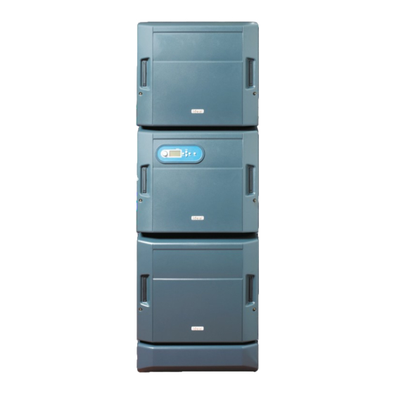
EVOMOD
250 500 750 1000
When replacing any part on this appliance, use only spare parts that you can be assured conform to the safety and performance
specification that we require. Do not use reconditioned or copy parts that have not been clearly authorised by Ideal.
For the very latest copy of literature for specification and maintenance practices visit our website www.idealcommercialboilers.com
where you can download the relevant information in PDF format.
August 2018
UIN 206810 A06
Advertisement
Table of Contents

Related Manuals for IDEAL EVOMOD 250


Summary of Contents for IDEAL EVOMOD 250
- Page 1 When replacing any part on this appliance, use only spare parts that you can be assured conform to the safety and performance specification that we require. Do not use reconditioned or copy parts that have not been clearly authorised by Ideal.
-
Page 2: Performance Data
Installation and Servicing Instructions or as otherwise recommended by Ideal Boilers in writing. If in doubt please enquire. CAUTION. To avoid the possibility of injury during the installation, servicing or cleaning of this appliance, care should be taken when handling edges of sheet steel components. -
Page 3: Table Of Contents
GENERAL CONTENTS 250, 500, 750 & 1000 Natural Gas only Boiler Assembly - exploded view ........15 Destination Countries: GB, IE Boiler Clearances ............14 Boiler Dimensions ..........7, 8, 9, 10 Commissioning and Testing ...........31 Electrical Connections ........21, 22, 23 Electrical Supply..............6 Fault Finding ..............48 Flue Installation ..............5 Gas Safety Regulations ............4... -
Page 4: Gas Safety Regulations
The Water Fittings Regulations or Water byelaws in Scotland. • The Current I.E.E. Wiring Regulations. The EVOMOD 250 comprises of a single module capable of delivering 250kW. Where no specific instructions are given, reference should be made to the relevant British Standard Code of Practice. -
Page 5: Flue Installation
Advice regarding the availability of proprietary types of flue gas supply and labelled as 'unsafe' until corrective action can be system can be obtained by contacting Ideal Boilers. taken. All joints or connections in the flue system must be impervious Terminal Position to condensate leakage. -
Page 6: Electrical Supply
Guidance Notes on Water Treatment in Central Heating Systems. roof spaces and ventilated underfloor spaces. Ideal Boilers recommend the use of Fernox Copal or MB1 The boiler must be vented. There must be no low points between or GE Betz Sentinel X100 inhibitors and associated water... - Page 7 GENERAL BOILER DIMENSIONS AND CONNECTIONS - 250 MODEL All dimensions shown in mm Installation & Servicing...
- Page 8 GENERAL BOILER DIMENSIONS AND CONNECTIONS - 500 MODEL All dimensions shown in mm Installation & Servicing...
-
Page 9: Boiler Dimensions
GENERAL BOILER DIMENSIONS AND CONNECTIONS - 750 MODEL All dimensions shown in mm Installation & Servicing... - Page 10 GENERAL BOILER DIMENSIONS AND CONNECTIONS - 1000 MODEL All dimensions shown in mm Installation & Servicing...
- Page 11 GENERAL HEADER KITS All dimensions shown in mm Installation & Servicing...
- Page 12 GENERAL HEADER KITS All dimensions shown in mm Installation & Servicing...
- Page 13 GENERAL HEADER KITS All dimensions shown in mm Installation & Servicing...
-
Page 14: Boiler Clearances
Should these conditions not apply either lower the pump position or raise the cistern above the minimum requirement specified by Ideal Boilers. isolation valves should be fitted as close to the pump as possible. -
Page 15: Boiler Assembly - Exploded View
INSTALLATION 11 SEALED SYSTEM REQUIREMENTS Working pressure 6 bar maximum. of a shutdown both visual and audible alarms may be necessary. Particular reference should be made to BS. 6644 and Guidance Expansion vessels used must comply with EN 13831 and must be sized note PM5 "Automatically controlled steam and hot water boilers"... -
Page 16: Installation
INSTALLATION 13 PACKAGING REMOVAL / REMOVAL FROM PALLET Evomod 250, 500, 750 The boiler is delivered on a wooden pallet with protective cardboard packing pieces at the front. The side panels & bottom side panels are contained within cardboard packs strapped to the sides of the boilers. The footer is contained in a cardboard box, strapped to the boiler, or placed on the flue header pallet. - Page 17 INSTALLATION 14 ASSEMBLING THE BOILER Evomod 250, 500, 750 • Use the adjustable feet to level the 2 frames & lock in place with the backing nuts. • Position the boiler in its desired position. • Remove the 3 nuts & bolts securing each spacer frame •...
- Page 18 INSTALLATION 15 ASSEMBLING THE BOILERS ..CONTINUED 3. Remove the ‘push on’ connectors & M5 screws from the front of the frame. 4. Hang the side panels over the 2 retaining pins on the back of the frame then secure at the front using 2 ‘push on’ connectors & an M5 screw per panel.
- Page 19 INSTALLATION 16 WATER AND GAS HEADER INSTALLATION The flue header is supplied as standard with the boiler (not The water and gas header system is supplied as a fully 250 model). assembled self supporting unit capable of connecting the water and gas services direct to the rear of the module/s. See table on page 5 for guidance on maximum permissible flue duct system design 500kW &...
-
Page 20: Water Connections
INSTALLATION 17 CONT'D WATER AND GAS HEADER INSTALLATION 1000kW (note - refer to diagrams in Frame 16 for reference) adjustments are available within the header assembly to help align connections. These must be secured after any 1. Assemble the 2 pairs of flue manifold T pieces (long legs adjustments. - Page 21 INSTALLATION 19 GAS CONNECTION The header gas supply pipe terminates in a Rp 1 ¼” female thread connection (250 model), a R2” male taper connection (500 & 750 models) and a R2 ½” male taper connection (1000 model) A minimum working gas pressure of 17mb must be available at the boiler inlet with the boiler firing.
-
Page 22: Electrical Connections
INSTALLATION 22 EXTERNAL WIRING 3. Connection of Optional Module Pumps Module pumps External wiring MUST be in accordance with the current I.E.E. (BS7671) Wiring Regulations. For Ireland reference should be may be connected directly to the Boiler via the Installer made to the current ETCI rules for electrical installations. - Page 23 INSTALLATION 25 INSTALLER CONNECTIONS Connection 1: Inside Installer Wiring Box (front, right of Master Module) Connection 2: Inside Master PCB Box (top, right hand side of Master Module) Header Optional Opti on al Optional Opt ional Header He ader 0-10V Sensor Header 0-10V...
-
Page 24: Wiring Diagrams
INSTALLATION 26 PICTORIAL WIRING DIAGRAM Installation & Servicing... - Page 25 INSTALLATION 27 BASIC CONTROLS DISPLAY EVOMOD USER INTERFACE Ideal Mains On When the mains to the boiler is switched on a screen similar to the following will be displayed. Initialising Please Wait U/I PCB 330.E18 Pri’ PCB 332.E08 Off Mode...
- Page 26 The kW output number in the 1st line will vary depending on the The kW output number in the 1st line will vary depending on the maximum output of the boiler maximum output of the boiler Ideal 750kW Ideal 750kW Normal Operation Normal Operation Set Flow Temp’...
- Page 27 The kW output number in the 1st line will vary depending on the The kW output number in the 1st line will vary depending on the maximum output of the boiler maximum output of the boiler Ideal 750kW Ideal 750kW Normal Operation Normal Operation Set Flow Temp’...
- Page 28 INSTALLATION 30 EVOMOD USER INTERFACE - ADVANCED OPERATING INSTRUCTIONS SETTING TO 0-10V CHANGING THE MAXIMUM FLOW TEMPERATURE SETPOINT The boiler default setting is that the maximum flow temperature Press SELECT and then hold + and - down together for more than setpoint is 80°C 5s, the following screen will be displayed This feature limits the maximum flow temperature that can be set in...
- Page 29 INSTALLATION 31 EVOMOD USER INTERFACE - ADVANCED OPERATING INSTRUCTIONS - CONT. CHANGING THE CASCADE LOGIC The boiler default setting is that the boiler will operate at maximum efficiency, this is achieved by having as many burners switched on as possible with them operating at as low an output as possible This can be changed so that as few burners are switched on as possible operating at higher outputs Press SELECT and then hold + and - down together for more than 5s, the following screen will be displayed Installer Mode...
- Page 30 INSTALLATION 32 EVOMOD WITH SWITCHED LIVE OR 0-10V CONTROL Note: that the boiler requires a 2 minute pump overrun period. It is recommended that the pump overrun functionality is achieved by connecting the pump to the boiler Header Pump The boiler warranty will be invalid if this is not provided. connections via a relay (see diagram).
-
Page 31: Commissioning And Testing
DO NOT SMOKE. 34 INITIAL LIGHTING Ideal 750kW 1. Check that the system has been filled and the boiler is not air locked - air in the boiler could damage the heat Normal Operation exchanger. - Page 32 INSTALLATION 35 EVOMOD MODULE OPERATING SEQUENCE Standby Heat Demand from Master PCB On Fan On 2 m ins Fan P r e-P u rge Module Pump On Spark Generator On Gas Valve On Standby 5s Ignition Per iod Heat Less Demand from Master Flame Detected than 5 Ignition...
- Page 33 INSTALLATION 36 EVOMOD BOILER OPERATING SEQUENCE Standby Heat Demand from Switched Live or 0-10V Input Header Pump On Heat Demand Off Demand < 50kW Temp < Set point Heat Demand Off 1 Burner On Demand > 150kW Demand > 100kW 2 Burners On Heat Demand Off Demand >...
- Page 34 INSTALLATION 37 GENERAL CHECKS c. Refill and vent the system, clear all air locks and again Make the following checks for correct operation. check for water soundness. 1. The correct operation of ANY secondary system controls d. Balance the system. should be proved.
-
Page 35: Servicing
5. Remove and inspect the fan/venturi assembly. Refer to Ideal Boilers does not accept any liability resulting from Frame 45. the use of unauthorised parts or the repair and servicing of 6. - Page 36 17. Seal adjustment screw cap with tamper proof paint. 18. If the required CO level cannot be obtained with a CO/CO ratio below 0.004 then contact Ideal Boilers Installer/Technical Help Line - 01482 498376 Offset Adjustment Screw Maximum Rate Adjustment Screw...
- Page 37 SERVICING 44 CASING REMOVAL - CONT Module front cover 2. Using the two handles pull the module cover forwards and then pull the two support brackets forward to provide a temporary hanging point for the cover, carefully place the cover on the support brackets. Alternatively, the module cover can be placed on the floor adjacent to the module.
- Page 38 SERVICING 45 REMOVAL OF FAN / VENTURI FOR INSPECTION 1. Refer to Frame 40. 2. Remove the module front cover (refer to Frame 43). 3. Disconnect the electrical connections from the Module PCB. 7. Remove the four nuts and washers retaining the fan to the burner mounting plate.
- Page 39 SERVICING 46 REMOVAL OF BURNER ASSEMBLY AND BURNER CLEANING 1. Refer to Frame 40. 2. Refer to Frame 45 for removal of fan/venturi. 3. Disconnect the ignition lead cap, earth lead and sensing lead ‘in line’ connector. 6. Carefully remove the burner, the burner can be cleaned internally only using a soft brush and/or vacuum.
- Page 40 SERVICING 47 HEAT EXCHANGER CLEANING 1. Refer to Frame 40. 2. Refer to Frame 45 for fan/venturi removal. 3. Refer to Frame 46 for burner assembly removal. 4. Inspect the exposed heat exchanger surface and if necessary clean with a suitable brush. 5.
- Page 41 SERVICING 50 GAS VALVE 1. Refer to Frame 40. 2. Remove the module front cover (refer to Frame 44). 3. Remove the electrical connections. Live Earth Neutral 6. Remove the four socket cap screws retaining the gas valve to the outlet flange. 4.
- Page 42 SERVICING 52 CONDENSATE BLOCKAGE PRESSURE SWITCH - Cont. 6. Remove the single cover fixing screw and remove the plastic cover. 7. Pull off the two electrical connections and transfer to the new switch. 8. Re-assemble in reverse order ensuring the pressure pipe is fitted to the positive (+) connection on the pressure switch.
- Page 43 SERVICING 55 FLAPPER VALVE REPLACEMENT 1. Refer to Frame 40. 2. Remove the module front cover (refer to Frame 44). 3. Remove the fan/venturi assemby (refer to Frame 45). 4. Remove the flapper valve by removing the 6 fixing screws. 5.
- Page 44 SERVICING 57 FLOW AND RETURN THERMISTOR REPLACEMENT 1. Refer to Frame 40. 6. Unscrew the flow and/or return thermistor. 2. Remove the module front cover (refer to Frame 44). 7. Fit the new thermistor/s. 3. Remove the right hand side panel (refer to Frame 15). 8.
- Page 45 SERVICING 59 FAN REPLACEMENT 1. Refer to Frame 40. 2. Remove the module front cover (refer to Frame 44). 3. Remove the fan assembly to a safe working area (Refer to Frame 45). 4. Remove the six venturi fixing screws, remove venturi and fit to new fan.
- Page 46 SERVICING 63 MASTER PCB REPLACEMENT 5. Remove the top right single fixing screw and swing the Master PCB Box out into the service position. Note: Observe all ESD Handling Procedures 6. Remove ALL plug in connections to the Master PCB Box 1.
- Page 47 SERVICING 65 HEAT EXCHANGER REPLACEMENT (MASTER & SLAVE MODULES) NB. Ignore items 5 and 6 for slave modules 1. Refer to Frame 40. 2. Remove the module front cover (refer to Frame 44). 3. Remove the right hand side panel (refer to Frame 15). 4.
-
Page 48: Fault Finding
FAULT FINDING 66 FAULT FINDING CHART - MAIN MENU Overheat Lockout Overheat Lockout Module 01 Go to Frame 68 Check System Pressure Press Reset, Overheat Lockout Check Flow Rate if Fault persists Check Pump Operation see Installation Guide Ignition Lockout Ignition Lockout Module 01 Press Reset,... - Page 49 FAULT FINDING 67 FAULT FINDING CHART - MAIN MENU CONT. Flapper Valve Fault Flapper Valve Fault Module 01 "Go to Frame 76 Check Flapper Valve Press Reset Flapper Valve Fault" Check Flap Wiring If Fault persists Check Flap Sensor see Installation Guide Module not connected Module not connected Module 01...
- Page 50 FAULT FINDING 68 OVERHEAT LOCKOUT Are the Boiler and CH/DHW system Fill and vent the system and open filled with water and are all Isolation all Isolation Valves, then Reset the Valves and Radiator Valves open? Boiler Check the Flow and Return Is the Flow/Return Differential across the boiler in excess of 35°C? Thermistors (refer to frame 74)
- Page 51 FAULT FINDING 71 FLAME LOSS Check the Detection Electrode and associated Harness for continuity, visual condition and position (refer to If the boiler is Reset, does the boiler Ignite Frame 46). Check if the Condensate Pipe is blocked. for a short time and then Extinguish Check if the Flue is blocked.
- Page 52 FAULT FINDING 73 FAN FAULT Rectify wiring & connections Does the wiring from the Fan to the PCB have secure connections at both ends and has not deteriorated? Replace main PCB Is there 230Vac at the blue and brown connections to the 3 way connection on the Fan? Replace Fan 74 FLOW THERMISTOR OR RETURN THERMISTOR OR THERMAL FUSE FAULT OR SAFETY THERMOSTAT OPEN...
- Page 53 FAULT FINDING 74A SAFETY THERMOSTAT OPEN The release of the thermostat will require the intervention of a qualified person in the boiler's maintenance; they will have to remedy the defect responsible for the unusual temperature rise and then carry out a verification (see protocol) of the heat exchanger before re-engaging the thermostat.
- Page 54 FAULT FINDING 77 MODULE NOT CONNECTED Is there 230V to the unconnected module? Replace the 230V wiring from the Master PCB to the Module PCB Replace the eBus wiring from the Does the eBus wiring from the Master PCB to the Master PCB to the Module PCB Module PCB have continuity? Replace the Module PCB...
- Page 55 FAULT FINDING 80 NO HEAT Set for On Mode (see Frame 28) Is the boiler set for On Mode? There is no Switched Live to the Boiler. Is there 230Vac at (A)? Ensure voltage is supplied to the boiler by correcting external wiring Does wiring to Header Pump have continuity and is to Rectify wiring to Header pump...
- Page 56 FAULT FINDING 81 NO DISPLAY Supply power to the boiler Is there 230Vac to the boiler at (B)? Connect the wiring from the Installer Is there 230Vac to the boiler at (C) Wiring Box to the Master PCB Box Connect the cable from the main PCB to Is the cable from the main PCB to the user interface the user interface PCB securely PCB connected securely?
- Page 57 FAULT FINDING 82 0-10V INTERFACE Set the boiler to accept a 0-10V input Is the boiler set to accept a 0-10V Input? (see Frame 27) Set the boiler to On Mode (see Frame 28) Is the boiler set to On Mode? Ensure between 2V and 10V is correctly Is a voltage of between 2V and 10V being supplied to connected to these terminals from the...
-
Page 58: Spare Parts
When replacing any part on this appliance use only spare parts that you can be assured conform to the safety and performance specification that we require. Do not use reconditioned or copy parts that have not been clearly authorised by Ideal. Failure to do so could affect safety or performance of this appliance. - Page 59 NOTES Installation & Servicing...
- Page 60 NOTES Installation & Servicing...
- Page 61 NOTES Installation & Servicing...
- Page 62 For details of courses please ring: ... 01482 498432 Ideal Boilers Ltd. pursues a policy of continuing improvement in the design and performance of its products. The right is therefore reserved to vary specification without notice.