Table of Contents
Advertisement
Quick Links
R
IVER
ADCP G
Information included herein is controlled by the Export Administration Regulations (EAR) and may
require an export license, license exception or other approval from the appropriate U.S. Government
agency before being exported from the United States or provided to any foreign person. Diversion
contrary to U.S. law is prohibited.
P
& R
RO
IO
UIDE
P
RO
© 2017 Teledyne RD Instruments, Inc. All rights reserved.
P/N 95B-6097-00 (October 2017)
Advertisement
Table of Contents
Troubleshooting

Related Manuals for Teledyne RIVERPRO


Summary of Contents for Teledyne RIVERPRO
- Page 1 UIDE P/N 95B-6097-00 (October 2017) © 2017 Teledyne RD Instruments, Inc. All rights reserved. Information included herein is controlled by the Export Administration Regulations (EAR) and may require an export license, license exception or other approval from the appropriate U.S. Government agency before being exported from the United States or provided to any foreign person.
- Page 2 Page ii EAR-Controlled Technology Subject to Restrictions Contained on the Cover Page.
-
Page 3: Table Of Contents
Computer Overview ............................. 5 Power Overview ............................6 Auto-Adaptive Water Profiling Mode ......................6 RiverPro/RioPro Options ........................6 Setting up the RiverPro/RioPro System ....................... 8 Bluetooth Connection .......................... 8 Serial Connection ..........................11 Connecting to the RiverPro/RioPro ....................12 Changing the Baud Rate in the ADCPs ................... 14 RiverPro/RioPro Recorder .......................... - Page 4 Yearly Maintenance Items ........................... 45 Maintenance Kit ........................... 45 End-Cap Removal Procedures ......................49 Transducer Head Assembly Removal ....................49 RiverPro/RioPro Re-assembly ........................50 Desiccant Bags ............................50 O-ring Inspection and Replacement ..................... 51 Transducer Head Assembly Replacement .................... 52 End-cap Replacement ..........................
- Page 5 CA – Communication Timeout ....................... 89 CB – Serial Port Control ........................90 CF – Set Control Flags........................91 CK – Save Command Parameters to Flash ..................92 CR – Restore Command Defaults ....................92 CS – Start Pinging (Go) ........................93 CState –...
- Page 6 Beam Correction Matrix Format ........................174 Reserved BIT Data Format..........................175 Checksum Data Format ..........................175 Decoding an RiverPro/RioPro Ensemble ...................... 176 Rules for the BroadBand Data Format PD0 ..................176 Recommended Data Decoding Sequence for BroadBand Data Format PD0 ........177 A - N ........................179...
- Page 7 Figure 14. I/O Cable Connector Lubrication ....................41 Figure 15. RiverPro/RioPro Compass Calibration Screen ................44 Figure 16. RiverPro/RioPro Compass Calibration Screen – Pitch/Roll ............45 Figure 17. RiverPro Assembly ........................47 Figure 18. RioPro Assembly ........................48 Figure 19.
- Page 8 RiverRay/RiverPro/RioPro Boat Wiring ..................64 Table 8: RiverPro/RioPro Specifications ....................73 Table 9: Outline Installation Drawings ....................74 Table 10: RiverPro/RioPro Input Command Summary ................81 Table 11: Serial Port Control ........................90 Table 12: Set Control Flags ........................91 Table 13: Restore Command Defaults .....................
- Page 9 XCLUSIONS AND MISSIONS This manual covers the RiverPro/RioPro ADCP hardware and firmware. For instructions on using a com- puter running the WinRiver II software, see the WinRiver II User’s Guide. For information on using the SxS Pro software, see the SxS Software User’s Guide.
- Page 10 For all your customer service needs including our emergency 24/7 technical support, call +1 (858) 842-2700 Self-Service Customer Portal Use our online customer portal at http://www.teledynemarine.com/rdi and click on the Support link to download manuals, firmware updates, software, or other Teledyne RDI documentation. Page x EAR-Controlled Technology Subject to Restrictions Contained on the Cover Page.
- Page 11 This paragraph format warns the reader of hazardous procedures (for example, activities that may cause loss of data or damage to the RiverPro/RioPro ADCP). This paragraph format tells the reader where they may find additional information.
- Page 12 OTES Page xii EAR-Controlled Technology Subject to Restrictions Contained on the Cover Page.
-
Page 13: Chapter 1 - A T A Glance
In this chapter: • RiverPro/RioPro Inventory • RiverPro/RioPro Options • System Overview • Computer Overview • Power Overview • Setting up the RiverPro/RioPro ADCP • Caring for the RiverPro/RioPro System Page 1 EAR-Controlled Technology Subject to Restrictions Contained on the Cover Page. -
Page 14: Riverpro/Riopro Inventory
Once purchased, a download link and activation code is sent. 95B-6127-00 Getting Started A printed reference card showing how to get started with the RiverPro/RioPro. A PDF version is included on the RiverPro/RioPro documentation CD. 95B-6123-00 Deployment Guide A Printed guide showing the steps needs for a successful deployment. -
Page 15: Riverpro Overview
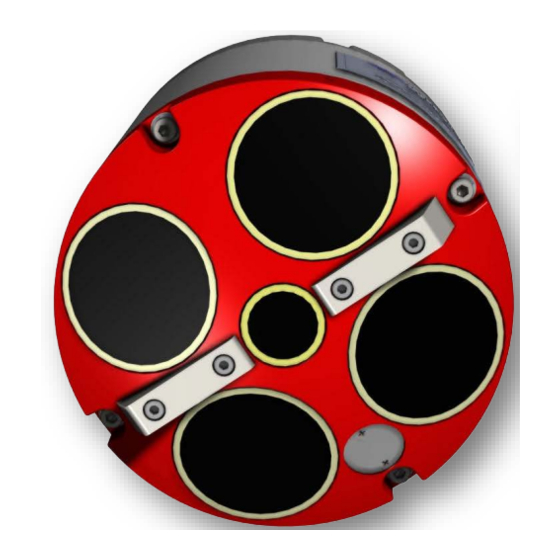
RiverPro and RioPro ADCP Guide October 2017 RiverPro Overview The RiverPro transducer assembly contains the end-cap, housing, transducer ceramics, and electronics. The standard acoustic frequencies are four 1200 kHz Janus beams and one 600 kHz vertical beam. See Outline Installation Drawings for dimensions and weights. -
Page 16: Riopro Overview
The RioPro is an upgraded 1200 kHz WorkHorse Rio Grande system that contains an updated transducer head, RiverPro electronics, and new end-cap. The system uses the original Rio Grande housing, shipping case, and I/O cable. The standard acoustic frequency is four 1200 kHz Janus beams. See the... -
Page 17: Boat Overview
RiverPro and RioPro ADCP Guide October 2017 Boat Overview The RiverRay/RiverPro/RioPro boat is designed to maintain the transducer at a constant depth in the wa- ter with minimal water flow disturbance. Figure 1. RiverRay/RiverPro/RioPro Boat Overview Computer Overview TRDI designed the RiverPro/RioPro ADCP to use a Windows® compatible computer. The computer con- trols the RiverPro/RioPro and displays its data, usually through our WinRiver II or SxS Pro programs. -
Page 18: Power Overview
RiverPro and RioPro ADCP Guide Power Overview The RiverPro/RioPro ADCP requires a DC supply between 10.5 volts and 18 volts. Either an external DC power supply or battery can provide this power. If using a battery, use the largest rated amp-hour battery as possible. - Page 19 GPS systems. GPS wiring and mounting kits are normally ordered in con- junction with new RiverPro/RioPro systems and any required boat modifications are performed at the factory. Common GPS wiring/mounting kits are shown below; additional kits and custom configurations are available –...
-
Page 20: Setting Up The Riverpro/Riopro System
RiverPro and RioPro ADCP Guide Setting up the RiverPro/RioPro System Use this section to connect the RiverPro/RioPro to a computer and establish communications. Install the RDI Tools software in order to communicate with the RiverPro/RioPro. For collecting data, install the WinRiver II, SxS Pro (optional), and Q-View (optional) software. - Page 21 RiverPro and RioPro ADCP Guide October 2017 3. Run the ParaniWin program and connect to the ADCP. With the Bluetooth modules used since August 2017 (or a repaired older unit where the Bluetooth module was replaced) select Mode 0 and you may or may not need to select Authentication (not Encryption). The Pin Code is 0000 (four zeros) and click Apply.
- Page 22 12. Click the Close button once more to exit the Peripherals Configuration Dialog. 13. Start a new measurement in WinRiver II. 14. On the Configuration Dialog, ensure the ADCP type matches the RiverPro/RioPro and the indicator next to the RiverPro/RioPro is green. Verify the blue LED on the RiverPro/RioPro ADCP is on.
-
Page 23: Serial Connection
3. Connect a battery or DC power supply to the power connectors. Verify that both the red and green LEDs light. After a few seconds the red LED should go out and the green LED will blink twice and then stay on. This indicates that the RiverPro/RioPro self-test has passed. Figure 3. -
Page 24: Connecting To The Riverpro/Riopro
October 2017 RiverPro and RioPro ADCP Guide Connecting to the RiverPro/RioPro To connect to the RiverPro/RioPro ADCP using the BBTalk software: Start BBTalk Start the BBTalk program by clicking Start, All Pro- grams, RD Instruments, RDI Tools, BBTalk. On the Connect To screen, select RiverRay. - Page 25 If the banner is not readable or visible: On the File menu, click Properties. Click the Auto Detect ADCP button. Click OK when the RiverPro/RioPro is detected. Try to wake up the RiverPro/RioPro again. Both BBTalk and the RiverPro/RioPro must use the same Baud rate.
-
Page 26: Changing The Baud Rate In The Adcps
115200 baud. The baud rate is controlled via the CB-command. The following proce- dure explains how to set the baud rate and save it in the RiverPro/RioPro. This procedure assumes using the program BBTalk that is supplied by Teledyne RD Instruments. -
Page 27: Riverpro/Riopro Recorder
Once the recorder fills up, the recorder MUST be erased before re-deploying the RiverPro/RioPro (start pinging again). If the RiverPro/RioPro is set to record data (MR1) and the recorder is full, the RiverPro/RioPro will not start pinging and will return a message. -
Page 28: Erasing Data From The Loop Recorder
October 2017 RiverPro and RioPro ADCP Guide 4. BBTalk displays current protocol status, filename being received, total size of receiving file and current number of bytes received (see Figure 5, page 16). 5. When recovery is complete, click OK. Figure 5. -
Page 29: Caring For The Riverpro/Riopro System
RiverPro and RioPro ADCP Guide October 2017 Caring for the RiverPro/RioPro System This section contains a list of items to be aware of every time the RiverPro/RioPro is handled, used, or de- ployed. Please refer to this list often. General Handling Guidelines •... - Page 30 October 2017 RiverPro and RioPro ADCP Guide OTES Page 18 EAR-Controlled Technology Subject to Restrictions Contained on the Cover Page.
-
Page 31: Chapter 2 - Installation
RiverPro and RioPro ADCP Guide October 2017 Chapter NSTALLATION In this chapter: • How to connect/disconnect the I/O cable • Cable wiring diagrams • Available mounts for the RiverPro/RioPro ADCP Page 19 EAR-Controlled Technology Subject to Restrictions Contained on the Cover Page. -
Page 32: Attaching The Boat Mounting Plate
ADCP even while it is in the shipping case. To attach the mounting plate: 1. Place the RiverPro/RioPro ADCP on a soft pad to protect the transducer face. 2. Install the mounting plate to the transducer end-cap using the six M6 bolts and flat washers. -
Page 33: Boat Assembly
4. Place the transducer into the boat. Slide the mounting plate until the rosette knob screws are in the slot. 5. Attach the ‘RiverPro/RioPro leash’ cable from the wire rope bridle to one of the mounting plate screws. Attach the support brace using the provided thumbscrews. -
Page 34: Boat Battery Connection
RiverPro and RioPro ADCP Guide Boat Battery Connection The RiverPro/RioPro system uses a 12v Lead Acid battery to provide power. The battery should be re- placed when the voltage falls below 11 VDC (measure with the cable connected and the power switch on). -
Page 35: I/O Cable And Dummy Plug
RiverPro/RioPro is in storage or is being handled. To disconnect the cable: 1. Place the RiverPro/RioPro on a soft pad to protect the transducer face. Remove the Strain Relief. 2. Release the retaining strap by pulling it over the connector. -
Page 36: Using The Cable Clips
2) The O-ring on the bottom of the end-cap connector can be damaged. 3) The molded urethane on the end-cap connector may separate from the brass insert. If the end-cap connector is damaged in any of these ways, the RiverPro/RioPro will flood. Using the Cable Clips If the retaining strap on the dummy plug or cable breaks, use the cable clips: 1. -
Page 37: Routing Cables
The cable can be easily replaced if it fails. Figure 8. Do not use Zip-Ties Directly on Cables When attaching the RiverPro/RioPro cable to a mount, do not zip-tie the cables directly to the structure. Zip-ties slowly cut through the cable’s outer jacket and cause leaks. Page 25... -
Page 38: Cable Wiring Diagram
Figure 10. Rio Grande I/O Cable Wiring Where shown, IN refers to signals going into the RiverPro/RioPro and OUT refers to signals coming out of the RiverPro/RioPro. If the RiverRay/RiverPro/RioPro cable is not available, a WorkHorse Rio Grande I/O cable can be used. -
Page 39: Mounting The Instrument
Use the following suggestions when mounting the RiverPro/RioPro ADCP: • It is desirable to rigidly mount the RiverPro/RioPro to the platform. Avoid the free spinning of the RiverPro/RioPro in this application. The RiverPro/RioPro must stay in the water at all times. -
Page 40: Over-The-Side Mounting
No matter what mounting style is used, the RiverPro/RioPro must be below the bubble layer. Bubbles will cling to the urethane faces of the RiverPro/RioPro and re- duce the range to almost nothing. Usually a mount somewhere aft of amidship is used. A stern mount will cause all sorts of problems due to propeller wake, bubbles, and turbulent water conditions. -
Page 41: In-Hull Mounting
October 2017 In-Hull Mounting The in-hull mounted RiverPro/RioPro is common when it is intended to keep the system on a single ves- sel or when over-the-side mounting is not practical for the vessel. For this type of mounting, there are is- sues of beam clearance and access. - Page 42 October 2017 RiverPro and RioPro ADCP Guide OTES Page 30 EAR-Controlled Technology Subject to Restrictions Contained on the Cover Page.
-
Page 43: Chapter 3 - Collecting Data
RiverPro and RioPro ADCP Guide October 2017 Chapter OLLECTING In this chapter: • RiverPro/RioPro Operation Overview • How to collect Real-Time data Page 31 EAR-Controlled Technology Subject to Restrictions Contained on the Cover Page. -
Page 44: Riverpro/Riopro Operation Overview
RiverPro and RioPro ADCP Guide RiverPro/RioPro Operation Overview Use the following figure and description on the next page to collect data with the RiverPro/RioPro: Inventory Verify all parts are present (see the RiverPro/RioPro Reference Card for a list of parts) -
Page 45: Glossary
Prepare for Discharge Measurement The Hydrologist arrives at the site with a RiverPro/RioPro and all of the ancillary equipment necessary to perform a discharge measurement. •... -
Page 46: Measurement Wizard
At this point the RiverPro/RioPro should be tested and the compass calibration completed; once those steps are complete it is ready to start the moving bed test. The RiverPro/RioPro is placed in the water, and the Hydrologist enters the command to start it pinging within the application. -
Page 47: Locating The Start And Stop Positions
While the RiverPro/RioPro is pinging, the Hydrologist positions the boat until the application shows that the RiverPro/RioPro is reliably collecting at least two bins of data and marks the position on the tagline for future reference. Measure the distance to the shore from the RiverPro/RioPro. The RiverPro/RioPro is positioned to the opposite bank where two bins of data are reliably collected. -
Page 48: Stationary Discharge Measurement
RiverPro/RioPro stationary at multiple locations across the channel, called verti- cals. For each location, the Hydrologist must maneuver the RiverPro/RioPro to a suitable position in the cross-section and hold that position while they collect data, typically for a minimum of 40 seconds. For... -
Page 49: Chapter 4 - Maintenance
In this chapter: • Where parts are located on the RiverPro/RioPro • How to spot problems • How to take the RiverPro/RioPro apart and put it back together • How to do periodic maintenance items on the RiverPro/RioPro Page 37... -
Page 50: Parts Location Drawings
October 2017 RiverPro and RioPro ADCP Guide Parts Location Drawings This section is a visual overview of the RiverPro/RioPro ADCP. Use the following figures to identify the parts used on the system. Figure 12. RiverPro Parts Location Page 38 EAR-Controlled Technology Subject to Restrictions Contained on the Cover Page. -
Page 51: Figure 13. Riopro Parts Location
RiverPro and RioPro ADCP Guide October 2017 Figure 13. RioPro Parts Location Page 39 EAR-Controlled Technology Subject to Restrictions Contained on the Cover Page. -
Page 52: Maintenance Schedule
To ensure continuous optimal results from the RiverPro/RioPro, TRDI recommends that every RiverPro/RioPro be returned to our factory for an inspection every two to three years. TRDI’s customer service will provide the unit with a thorough multi-point inspection and any refurbishment services needed to properly maintain the unit. -
Page 53: Periodic Maintenance Items
RiverPro and RioPro ADCP Guide October 2017 Periodic Maintenance Items These maintenance items should be done prior to using the RiverPro/RioPro. I/O Cable Connector Lubrication The I/O connectors require very little maintenance. They are designed to be used in harsh environments and thus limited amounts of dirt and grit do not affect their performance. -
Page 54: Cleaning The I/O Cable Connectors
3. Dry the transducer faces with low-pressure compressed air or soft lint-free towels. Always dry the RiverPro/RioPro before placing it in the storage case to avoid fungus or mold growth. Do not store the RiverPro/RioPro in wet or damp locations. -
Page 55: Final Storage Or Shipping Preparation
3. Dissemble the boat (if required) and place it into its own shipping container. 4. Place the transducer in the foam cutouts in the bottom of the shipping case. The RiverPro trans- ducer will fit into the shipping case with the mounting plate installed. If stored this way, remove the extra foam material that has already been pre-cut from the instrument cavity. -
Page 56: Figure 15. Riverpro/Riopro Compass Calibration Screen
RiverPro and RioPro ADCP Guide 3. Select Use Pitch/Roll? • Click No if the RiverPro/RioPro will not be subject to pitch and roll (i.e. calm water) (see Figure 15). This calibration requires two rotations (one for calibration and one for verification). -
Page 57: Yearly Maintenance Items
The O-rings, desiccant and hardware should be replaced every one to two years. Maintenance Kit Table 2 and Table 3 lists the items in the maintenance kits. These kits are required when the RiverPro/Ri- oPro has been opened. The maintenance kit includes the following tools and spare parts. -
Page 58: Table 3: Riopro/Rio Grande Maintenance Kit
October 2017 RiverPro and RioPro ADCP Guide Item # Part # Description M5WASHSPL Split-Washer, SST M5WASHSTD Flat Washer, 10MM OD, SST M5X0.8X20SHCS Socket head cap screw, 316SS M5X0.8X30SHCS Socket head cap screw, 316SS Table 3: RioPro/Rio Grande Maintenance Kit Item #... -
Page 59: Figure 17. Riverpro Assembly
RiverPro and RioPro ADCP Guide October 2017 Figure 17. RiverPro Assembly Page 47 EAR-Controlled Technology Subject to Restrictions Contained on the Cover Page. -
Page 60: Figure 18. Riopro Assembly
October 2017 RiverPro and RioPro ADCP Guide Figure 18. RioPro Assembly Page 48 EAR-Controlled Technology Subject to Restrictions Contained on the Cover Page. -
Page 61: End-Cap Removal Procedures
These signs may indicate that there is internal pressure inside the unit. If the RiverPro/RioPro flooded, there may be gas under pressure inside the housing. As a precaution, loosen the four end-cap bolts to vent the system. -
Page 62: Riverpro/Riopro Re-Assembly
• Make sure all printed circuit boards, spacers, cables, and screws have been installed. • Install one fresh bag of desiccant just before closing the RiverPro/RioPro (see Desiccant Bags). Desiccant Bags Desiccant bags are used to dehumidify the housing interior. Desiccant is essential in deployments with plastic housings. -
Page 63: O-Ring Inspection And Replacement
Defects must be less than 0.1 mm (0.004 in.). Always use new O-rings. Weak or damaged O-rings will cause the RiverPro/RioPro to flood. 2. Clean and inspect the O-ring grooves. Be sure the grooves are free of foreign matter, scratches, indentations, corrosion, and pitting. -
Page 64: Transducer Head Assembly Replacement
Use rubber bands to hold the wiring in place as necessary. If the O-ring is not in the groove or if a wire or other object is pinched, the RiverPro/RioPro will flood. 4. Examine the transducer assembly bolts and washers for corrosion; replace if necessary. Use Fig- ure 17 and Figure 18 for parts identification. -
Page 65: End-Cap Replacement
RiverPro/RioPro will flood. 5. Examine the end-cap assembly bolts and washers for corrosion; replace if necessary. Use Figure 17 and Figure 18 for parts identification. All hardware items are needed to seal the RiverPro/Ri- oPro properly. - Page 66 October 2017 RiverPro and RioPro ADCP Guide OTES Page 54 EAR-Controlled Technology Subject to Restrictions Contained on the Cover Page.
-
Page 67: Chapter 5 - Testing The River Pro /Rio Pro
RiverPro and RioPro ADCP Guide October 2017 Chapter ESTING THE IVER In this chapter, you will learn: • Testing the RiverPro/RioPro with WinRiver II or BBTalk • Test Results Page 55 EAR-Controlled Technology Subject to Restrictions Contained on the Cover Page. -
Page 68: Testing The System Using Winriver Ii
October 2017 RiverPro and RioPro ADCP Guide This chapter explains how to test the RiverPro/RioPro using the WinRiver II, SxS Pro, and BBTalk pro- grams. Test the RiverPro/RioPro: • When you first receive the RiverPro/RioPro. • Before each deployment or every six months. -
Page 69: Testing The System With Sxs Pro
4. At the end of the test, click the Stop PC2 button to end the PC2 test. Click Exit to exit the ADCP Tests dialog. The tests should be run while the RiverPro/RioPro ADCP is in water. Running the test in air will not harm the RiverPro/RioPro, but some tests may fail in air. -
Page 70: Test Results
Instrument Transformation Matrix PS3 sends information about the transducer beams. The RiverPro/RioPro uses this information in its co- ordinate-transformation calculations; for example, the output may look like this: >ps3 Last Save Time: 14/09/26,17:16:41.39... -
Page 71: Pre-Deployment Test
VBeam Offset (mm) 0 > If the RiverPro/RioPro has beam angle errors, they are reflected in the instrument transformation matrix and the Beam Directional matrix. This matrix, when multiplied by the raw beam data gives currents in the x, y, z, and e directions. - Page 72 October 2017 RiverPro and RioPro ADCP Guide OTES Page 60 EAR-Controlled Technology Subject to Restrictions Contained on the Cover Page.
-
Page 73: Chapter 6 - Troubleshooting
RiverPro and RioPro ADCP Guide October 2017 Chapter ROUBLESHOOTING In this chapter: • LED colors and troubleshooting Float wiring diagram • Page 61 EAR-Controlled Technology Subject to Restrictions Contained on the Cover Page. -
Page 74: System Status And Led Behavior
RiverPro and RioPro ADCP Guide System Status and LED Behavior The RiverPro/RioPro LED behavior is illustrated in Table 5. The blue LED indicates Bluetooth connection status. The green and red LEDs depict the system status and diagnostic information respectively. Table 5. -
Page 75: Fuse Replacement
Check Bluetooth setup on PC computer. Bluetooth connection is intermittent Out of range – The PC must be in a clear line of sight to the RiverPro/RioPro. RiverPro/RioPro internal temperature may be above 50° C. Move the RiverPro/RioPro to a cooler location and attempt to communicate again. -
Page 76: Boat Wiring Diagram
October 2017 RiverPro and RioPro ADCP Guide Boat Wiring Diagram Figure 21. RiverRay/RiverPro/RioPro Boat Wiring Diagram Table 7: RiverRay/RiverPro/RioPro Boat Wiring To GPS (J1) RiverRay I/O Connector (J2) 8pin micro/change LPMIL-8-FS Connector Pin Number Function Function Pin Number ← →... -
Page 77: Returning
TRDI ETURNING YSTEMS TO ERVICE In this chapter: • How to pack and ship the RiverPro/RioPro • How to get a RMA number • Where to send your RiverPro/RioPro for repair Page 65 EAR-Controlled Technology Subject to Restrictions Contained on the Cover Page. -
Page 78: Shipping The Riverpro/Riopro
All costs associated with customer-applied coatings will be at the customer's expense. When shipping the RiverPro/RioPro ADCP through a Customs facility, be sure to place the unit so identi- fying labels are not covered and can be seen easily by the Customs Inspector. Failure to do so could delay transit time. -
Page 79: Returning Systems To The Trdi Factory
When shipping the system to TRDI from either inside or outside the United States, the following instruc- tions will help ensure the RiverPro/RioPro ADCP arrives with the minimum possible delay. Any deviation from these instructions increases the potential for delay. -
Page 80: Returning Systems To Trdi Europe Factory
Carrier route and flight numbers for all flights the package will take Returning Systems to TRDI Europe Factory When shipping the system to TRDI Europe, the following instructions will help ensure the RiverPro/Ri- oPro ADCP arrives with the minimum possible delay. Any deviation from these instructions increases the potential for delay. - Page 81 RiverPro and RioPro ADCP Guide October 2017 Mark the package(s) as follows: To: Teledyne RD Instruments, Inc. (RMA Number) 2A Les Nertieres 5 Avenue Hector Pintus 06610 La Gaude, France Step 4 - Include Proper Customs Documentation The Customs statement must be completed. It should be accurate and truthfully contain the following in- formation.
- Page 82 October 2017 RiverPro and RioPro ADCP Guide OTES Page 70 EAR-Controlled Technology Subject to Restrictions Contained on the Cover Page.
-
Page 83: Chapter 8 - Specifications
RiverPro and RioPro ADCP Guide October 2017 Chapter PECIFICATIONS In this chapter, you will learn: • Specifications • Outline Installation Drawings Page 71 EAR-Controlled Technology Subject to Restrictions Contained on the Cover Page. - Page 84 The speed of sound in the water is another factor that linearly contributes to the RiverPro/RioPro velocity calculation. This parameter can be provided to the RiverPro/RioPro by an external source, provided as a priori information to the instrument, or calculated in real-time by the instrument itself.
-
Page 85: Table 8: Riverpro/Riopro Specifications
Bluetooth binary output at 115,200 baud. Range up to 200m. Optional Radio modem, range >30km (line of sight) Environmental Standard depth rating The RiverPro/RioPro is intended to be operated as a surface mounted system only. No depth rating is provided. Operating temperature -5° to 45°C Storage temperature -20°... -
Page 86: Outline Installation Drawing
3 For beam-averaged depth data 4 Assumes uniform water temperature and salinity profile 5 For combined tilt <+/-70° and dip angle <70° Outline Installation Drawing The following drawings show the standard RiverPro/RioPro dimensions and weights. Table 9: Outline Installation Drawings Description... -
Page 87: Figure 22. 96B-6060 Riverpro Outline Installation Drawing
RiverPro and RioPro ADCP Guide October 2017 Figure 22. 96B-6060 RiverPro Outline Installation Drawing Page 75 EAR-Controlled Technology Subject to Restrictions Contained on the Cover Page. -
Page 88: Figure 23. 967-6150 Riopro 1200 Khz Outline Installation Drawing
October 2017 RiverPro and RioPro ADCP Guide Figure 23. 967-6150 RioPro 1200 kHz Outline Installation Drawing Page 76 EAR-Controlled Technology Subject to Restrictions Contained on the Cover Page. -
Page 89: Chapter 9 - Commands
RiverPro and RioPro ADCP Guide October 2017 Chapter OMMANDS In this chapter: • How to enter commands • Data output processing • Firmware updates • Command descriptions Page 77 EAR-Controlled Technology Subject to Restrictions Contained on the Cover Page. -
Page 90: Data Communication And Command Format
Using WinRiver II or SxS Pro for real-time deployments to develop the command file will ensure that the RiverPro/RioPro is set up correctly. The commands shown in Table 10 directly affect the range of the RiverPro/RioPro, the standard deviation (accuracy) of the data, and battery usage. -
Page 91: Data Output Processing
The RiverPro/RioPro will continue to be configured from volatile memory until it receives a CR-command or until the volatile memory loses its backup power. If the RiverPro/RioPro receives a CR0 it will load into volatile memory the command set last stored in non-volatile memory (semi-permanent user settings) through the CK-command. -
Page 92: Feature Upgrades
2. Run the NGSPActivate.exe program to enable the Section-By-Section features. If this feature was ordered with the system, it will already be installed. For field upgrades, the file can be renamed by TRDI, for example to RR_SNxxx.exe where xxx is the RiverPro/RioPro ADCP’s serial number and will be e-mailed. -
Page 93: Command Summary
October 2017 Command Summary Table 10 gives a summary of the RiverPro/RioPro input commands, their format, and a brief description of the parameters they control, and the factory default command settings. When newer firmware versions are released, some commands may be modified or added. - Page 94 October 2017 RiverPro and RioPro ADCP Guide Table 10: RiverPro/RioPro Input Command Summary Command Default Description ErAsE recorder Show memory usge MN RP Set deployment name (1….6 characters) MR 0 Set recorder on/off [0=off, 1=on) Streaming download (addr, nbytes) Y-modem download...
- Page 95 RiverPro and RioPro ADCP Guide October 2017 Table 10: RiverPro/RioPro Input Command Summary Command Default Description ZB 0 Bandwidth [0=Wide (25%), 1=Narrow (6.25%)] ZC 064 Correlation Threshold (counts) [0..255] ZD 111100000 Data Out {v;c;a;p;s;*;*;*;*} ZF 020 Blanking Distance (cm) [0-500]...
-
Page 96: Command Descriptions
Setting, and description. When appropriate, we include amplifying notes and examples. If a numeric value follows the command, the RiverPro/RioPro uses it to set a processing value (time, range, percentage, processing flags). All measurement values are in metric units (mm, cm, and dm). -
Page 97: Break
Firmware Version: 56.xx Firmware Version: 56.xx > > When a break is sent, the first line of the banner indicates the RiverPro/RioPro’s communication configu- ration: • QBREAK A - RiverPro/RioPro response to a hard break on the serial RS-232 I/O cable. -
Page 98: Ol - Display Feature List
The Section-By-Section (SxS) feature allows transects to be completed by measuring at different user selected points on the river. This makes it possible to measure streams that are frozen over. Manual Profile Modes allow the RiverPro/RioPro to override the automatic profiling mode and adds additional water profiling commands (see Water Profiling Commands) Contact your local sales representative if you are interested in upgrading your system. -
Page 99: Bottom Track Commands
The RiverPro/RioPro interleaves bottom-track pings with water-track pings (see TP command). If BP = zero, the RiverPro/RioPro does not collect bottom-track data. The RiverPro/RioPro automatically extends the ensemble interval (TE) if BP x TP > TE. Page 87 EAR-Controlled Technology Subject to Restrictions Contained on the Cover Page. -
Page 100: Bx - Maximum Tracking Depth
The BX-command sets the maximum tracking depth used by the RiverPro/RioPro during bottom tracking. This prevents the RiverPro/RioPro from searching too long and too deep for the bottom, allowing a faster ping rate when the RiverPro/RioPro loses track of the bottom. -
Page 101: Control System Commands
The CA command sets the activity timeout period, in seconds. The activity timer is reset when a valid command is received. If no valid command is received within the timeout period, the RiverPro/RioPro will go to sleep or deploy itself, depending on the setting of the CT (Turnkey) command. If... -
Page 102: Cb - Serial Port Control
(see Changing the Baud Rate in the ADCPs). After valid CB parame- ters are entered, the RiverPro/RioPro responds with a “>” prompt. Then change the ex- ternal device’s communication parameters to match the RiverPro/RioPro parameters be- fore sending another command. -
Page 103: Cf - Set Control Flags
<Enter> sent to the RiverPro/RioPro is not echoed. This feature manually controls ping timing within the ensemble. Note the prompt output by the RiverPro/RioPro when ready to ping is a less-than symbol (<), to distinguish it from the normal com- mand prompt. -
Page 104: Ck - Save Command Parameters To Flash
This can happen after several months without any power applied to the system (Note that this battery will recharge as soon as power is reapplied). If the RiverPro/RioPro is stopped by removing the power while pinging, it will restart pinging and output data next time power is applied. -
Page 105: Cs - Start Pinging (Go)
Description Use CS (or the Tab key in BBTalk) to tell the RiverPro/RioPro to start pinging its trans- ducers and collecting data as programmed by the other commands. If the... -
Page 106: Cw - Output The Last Stored Ensemble
Sending the CZ-command powers down the RiverPro/RioPro. RiverPro/RioPro pro- cessing is interrupted and the RiverPro/RioPro goes in the STANDBY mode (RAM is maintained). If the RiverPro/RioPro is running a sensor test under battery power, a fully charged battery will be discharged in a few days. >cz... -
Page 107: Environmental Commands
(e.g., magnetic declination). Example The RiverPro/RioPro is mounted in place on a moving ship. Beam 3 has been rotated 45 clockwise (+45) from the ship’s centerline. Use the EA command to tell the RiverPro/Ri- oPro where beam 3 is in relation to the ship’s centerline. To convert +45 to an EA- command value, multiply the desired alignment angle in degrees by 100: EA = +45.00 ×... -
Page 108: Eb - Heading Bias
See the primer for information on speed of sound cal- culations. If the EZ Speed of Sound field = 0, the RiverPro/RioPro overrides the manually-set EC value and calculates speed of sound using the values determined by transducer depth (ED), salinity (ES), and transducer temperature (ET). -
Page 109: Ed - Depth Of Transducer
3.50 × 100 = 350 = EH00350 If the EZ Heading field = 1, the RiverPro/RioPro overrides the manually set EH value and uses heading from the transducer’s internal sensor. If the sensor is not available, the RiverPro/RioPro uses the manual EH setting. -
Page 110: Ep - Pitch (Tilt 1)
ER = -3.50 × 100 = -350 = ER-00350 If the EZ Roll field = 1, the RiverPro/RioPro overrides the manually set ER value and uses roll from the transducer’s internal tilt sensor. If the sensor is not available, the RiverPro/RioPro uses the manual ER setting. -
Page 111: Et - Temperature
EU sets the RiverPro/RioPro system orientation, up or down. If the EZ Roll field is not zero, the RiverPro/RioPro overrides the manually set EU value and uses orientation from the transducer’s internal tilt sensor. If the sensor is not available, the RiverPro/RioPro uses the manual EU setting. -
Page 112: Ex - Coordinate Transformation
2. Setting EX bit 3 (Use Tilts) to 0 collects tilt data without using it in the ship or earth- coordinate transformations. 3. Each RiverPro/RioPro uses its own beam calibration matrix to correct data for beam pointing errors (e.g., if the beams erroneously point toward 21 degrees instead of 20 degrees). -
Page 113: Figure 25. X, Y, And Z Velocities
October 2017 B e am C oor d in a t e Sy st e m s The RiverPro/RioPro can produce velocity measurements in any of the following four sets of coordinate axes by setting the command. Except for the first, they are all right-handed orthogonal systems. The user operational requirements dictate the best coordinate system to be used. -
Page 114: Figure 26. Riverpro/Riopro Coordinate Transformation
October 2017 RiverPro and RioPro ADCP Guide Figure 26. RiverPro/RioPro Coordinate Transformation The importance of the ship axis is that the attitude angles (pitch, roll, and heading) measure the orienta- tion of the ship axes relative to the earth axes, regardless of up/down orientation. The sense of internal sensors Tilt 1 (pitch) and Tilt 2 (roll) is positive for counterclockwise tilts respectively about the S and F axes, using the right-hand rule (see Figure 27). -
Page 115: Ez - Sensor Source
When a switch value is non-zero, the RiverPro/RioPro overrides the manual E-command setting and uses data from the appro- priate sensor. If no sensor is available, the RiverPro/RioPro defaults to the manual E- command setting. The following table shows how to interpret the sensor source switch settings. -
Page 116: Recorder Commands
Once the recorder fills up, the recorder MUST be erased before re-deploying the RiverPro/RioPro (start pinging again). If the RiverPro/RioPro is set to record data (MR1) and the recorder is full, the RiverPro/RioPro will not start pinging and will return a message. -
Page 117: Mm - Show Memory Usage
= 0, turn recorder off; n = 1, turn recorder on) Default Recommended Setting. Use as needed. Description Use the MR command to turn the recorder on/off. Using the recorder will slow down the RiverPro/RioPro’s ping rate. Page 105 EAR-Controlled Technology Subject to Restrictions Contained on the Cover Page. -
Page 118: Mq - Streaming Download
October 2017 RiverPro and RioPro ADCP Guide MQ – Streaming Download Purpose Downloads the recorder. Format MQ (StartAddr, nbytes) Range StartAddr: 0 to FFFFFE (Hex) nBytes: 1 to 16777216 (decimal) Default Recommended Setting. Use BBTalk to recover data (see Recovering Data from the Loop Recorder). -
Page 119: Performance And Testing Commands
Sends/displays results of a series of RiverPro/RioPro system diagnostic tests. Format Recommended Setting. Use as needed. Description These diagnostic tests check the major RiverPro/RioPro modules and signal paths. These tests check the following boards/paths. • Recorder - verifies recorder operation (this test takes several minutes to com- plete). -
Page 120: Pc - User Interactive Built-In Tests
October 2017 RiverPro and RioPro ADCP Guide PC – User Interactive Built-In Tests Purpose Sends/displays results of user-interactive RiverPro/RioPro system diagnostic tests. Format PCnnn nnn = 0, 2, 20, 4, 40 (PC0 = Help menu; see below for others) Range Recommended Setting. - Page 121 RiverPro and RioPro ADCP Guide October 2017 P C 4 – Di s p l ay Vo lt a g e Mo n it or A D C D at a The PC4 Batt (V) value is ~ 0.8 volts below the supply voltage. VDD1 and VDD3 should be within 0.01 volts of the values shown in the example data.
-
Page 122: Pd - Set Output Format
Recommended Setting. Use as needed. Description See below. P S 0 – Sy st e m C onf i g ur at i on PS0 sends the RiverPro/RioPro hardware/firmware information. For example, the output may look like this: >ps0 System:... -
Page 123: Pt - Built-In Tests
VBeam Offset (mm) 0 > If the RiverPro/RioPro needs beam angle corrections, a TRDI calibrated beam angle matrix is loaded into the instrument. This is done when the instrument is manufactured. For details, download a copy of the RiverPro/RioPro Coordinate Transformation booklet (http://www.teledynemarine.com/rdi). - Page 124 Each nibble represents the result for a particular beam (most significant nibble = beam 1, least significant nibble = beam 8) (four beam RiverPro/RioPro systems utilize the four most significant nibbles). In this example, TRDI only describes which bit is set for beam 2 for a given failure type.
- Page 125 RiverPro and RioPro ADCP Guide October 2017 H-Gain W-BW L-Gain W-BW Lag Bm1 0 1000 1000 1000 1000 1000 1000 1000 1000 H-Gain N-BW L-Gain N-BW Lag Bm1 0 1000 1000 1000 1000 1000 1000 1000 1000 H-Gain W-BW L-Gain W-BW...
- Page 126 October 2017 RiverPro and RioPro ADCP Guide RAM test...PASS > P T 13 = R OM T e st >pt13 ROM Test....PASS [ 7b5f ] > P T 14 = R e cor d er T es t >pt14 Recorder Test....PASS >...
-
Page 127: Pf - Results From Most Recent Pa Tests
RiverPro and RioPro ADCP Guide October 2017 PF – Results from most recent PA tests Purpose Outputs the results of the last PA test. Format Recommended Setting. Use as needed. Description This command gives a summary of the last PA test. -
Page 128: Sensor Control Commands
Default Recommended Setting. Use WinRiver II to calibrate the compass. The compass must be calibrated if the boat and/or mounting have changed or the RiverPro/RioPro is moved to a new location. Description Command used to display compass module information, enter calibration mode, and set compass module parameters. -
Page 129: Sf - External Nmea Menu
ISM Zero offsets Disabled, Pitch 0.000000 deg, Roll 0.000000 deg Save new values? Y|[N] Save Done SF – External NMEA Menu Purpose Sets the RiverPro/RioPro GPS input port to match the external GPS unit. Format Range n = 0, 1, 2, 3-9 Default Recommended Setting. - Page 130 Send the SF2 command to display the GPS string the instrument is receiving. If the baud rate between the GPS and the RiverPro/RioPro does not match, the GPS string will not be readable (i.e. “garbage” charac- ters). If the GPS is not connected, there is no output.
-
Page 131: Si - Internal Nmea Menu
RiverPro and RioPro ADCP Guide October 2017 SI – Internal NMEA Menu Purpose Used for Internal GPS status and diagnostic information. Format n = 0, 1, 2, 10, -1, 11, 20, 30 Range Default Recommended Setting. Use as needed. Description Use the SI command to retrieve Internal GPS status and diagnostic information. -
Page 132: Timing Commands
Recommended Setting. The default setting for this command is recommended for most applications. Description During the ensemble interval set by TE, the RiverPro/RioPro collects one automatic en- semble. If TE = 00:00:00.00, the RiverPro/RioPro starts collecting the next ensemble immediately after processing the previous ensemble. -
Page 133: Tf - Time Of First Ping
CS command (see notes). 1. If a TF command is sent to the RiverPro/RioPro, the CS command must also be sent before deploying the RiverPro/RioPro. 2. If the entry is not valid, the RiverPro/RioPro sends an error message and does not update the wake-up time. -
Page 134: Ts - Set Real-Time Clock
1. When the RiverPro/RioPro receives the carriage return after the TS command, it enters the new time into the real-time clock and sets hundredths of seconds to zero. 2. If the entry is not valid, the RiverPro/RioPro sends an error message and does not update the real-time clock. -
Page 135: Vertical Beam Range Commands
RiverPro and RioPro ADCP Guide October 2017 Vertical Beam Range Commands The following commands define the criteria used to collect the vertical beam data. The vertical beam is not available for RioPro systems. Standard Vertical Beam Range Commands This section lists the Vertical Beam commands. -
Page 136: Water Profiling Commands
WD 1110000001 ----------- Data Out {v;c;a;p;s;*;*;*;*;m} WM 0003 ----------------- Water Profiling Mode [2,3,12] W? ---------------------- Display W-Command Menu Manual Mode Water Profiling WM2 and WM12 are feature upgrades for RiverPro/RioPro systems (see Feature Upgrades). This upgrade adds the following highlighted commands. -
Page 137: Wc - Correlation Threshold
WD uses firmware switches to tell the RiverPro/RioPro the types of data to collect. The RiverPro/RioPro always collects header data, fixed and variable leader data, and check- sum data. Setting a bit to one tells the RiverPro/RioPro to collect that data type. The bits are described as follows:... -
Page 138: Wf - Blank After Transmit
WN200 Recommended Setting. Set using WinRiver. Description The range of the RiverPro/RioPro is set by the number of depth cells (WN) times the size of each depth cell (WS). Page 126 EAR-Controlled Technology Subject to Restrictions Contained on the Cover Page. -
Page 139: Wo - Number Of Subpings
WP sets the number of pings to average in each ensemble before sending/recording the data. 1. If WP = zero the RiverPro/RioPro does not collect water-profile data. 2. The RiverPro/RioPro automatically extends the ensemble interval (TE) if WP x TP > TE. WS – Bin Size Purpose Selects the volume of water for one measurement cell (bin). -
Page 140: Wv - Ambiguity Velocity
The lower the value of the WV command, the lower the single-ping standard deviation. Set the WV command based on the maximum apparent velocity (RiverPro/RioPro motion plus water speed). The following formula is used to determine the setting of the WV com- mand: WV = (Max. -
Page 141: Vertical Beam Profile Commands
Recommended Setting. The default setting for this command is recommended for most applications. Description: Narrow bandwidths allow the RiverPro to profile farther, but the standard deviation is increased by as much as 2.5 times. ZC – Vertical Beam Correlation Threshold... -
Page 142: Zd - Vertical Beam Data Out
ZD uses firmware switches to tell the RiverPro the types of data to collect and process. The RiverPro always collects header data, fixed and variable leader data, and checksum data. Setting a bit to one tells the RiverPro to collect and process that data type. The bits are described as follows:... -
Page 143: Zg - Vertical Beam Gain
Recommended Setting. The default setting for this command is recommended for most applications. Description: ZG0 tells the RiverPro to reduce receiver gain by 40 dB. This may increase data reliability in shallow-water applications where there is a high content of backscatter material. ZG1 (the default) uses the normal receiver gain. -
Page 144: Zn - Vertical Beam Number Of Bins
Recommended Setting. The default setting for this command is recommended for most applications. Description: The range of the RiverPro vertical beam is set by the number of bins (ZN) times the size of each bin (ZS). The backscatter level is also a factor in determining the range that can be effectively measured by the vertical beam. -
Page 145: Zs - Vertical Beam Bin Size
ZS010 Recommended Setting. The default setting for this command is recommended for most applications. Description: The RiverPro collects data over a number of bins. ZS sets the size of each bin in vertical centimeters. ZV – Vertical Beam Ambiguity Velocity Purpose: Sets the vertical beam radial ambiguity velocity. - Page 146 October 2017 RiverPro and RioPro ADCP Guide OTES Page 134 EAR-Controlled Technology Subject to Restrictions Contained on the Cover Page.
-
Page 147: Chapter 10 - Output Data Format
RiverPro and RioPro ADCP Guide October 2017 Chapter UTPUT ORMAT In this chapter: • PD0 output data format • Decoding an RiverPro/RioPro Ensemble Page 135 EAR-Controlled Technology Subject to Restrictions Contained on the Cover Page. -
Page 148: Pd0 Output Data Format
RiverPro and RioPro ADCP Guide PD0 Output Data Format This section shows the output data format of the RiverPro/RioPro and explains it in enough detail to help create your own data processing or analysis programs (see How to Decode an RiverPro/RioPro Ensem- ble). -
Page 149: Figure 28. Pd0 Standard Output Data Buffer Format
RiverPro and RioPro ADCP Guide October 2017 HEADER (6 BYTES + [2 x No. OF DATA TYPES]) ALWAYS OUTPUT FIXED LEADER DATA (59 BYTES) VARIABLE LEADER DATA (65 BYTES) WATER VELOCITY (2 BYTES + 8 BYTES PER DEPTH CELL) WATER CORRELATION MAGNITUDE (2 BYTES + 4 BYTES PER DEPTH CELL) -
Page 150: Header Data Format
October 2017 RiverPro and RioPro ADCP Guide Header Data Format BIT POSITIONS BYTE HEADER ID (7Fh) DATA SOURCE ID (7Fh) NUMBER OF BYTES IN ENSEMBLE SPARE NUMBER OF DATA TYPES OFFSET FOR DATA TYPE #1 OFFSET FOR DATA TYPE #2 OFFSET FOR DATA TYPE #3 ↓... -
Page 151: Table 18: Header Data Format
RiverPro and RioPro ADCP Guide October 2017 Header information is the first item sent by the RiverPro/RioPro to the output buffer. The RiverPro/Ri- oPro always sends the Least Significant Byte (LSB) first. Table 18: Header Data Format Hex Digit Binary Byte... -
Page 152: Fixed Leader Data Format
October 2017 RiverPro and RioPro ADCP Guide Fixed Leader Data Format BIT POSITIONS BYTE FIXED LEADER ID LSB 00h MSB 00h CPU F/W VER. CPU F/W REV. SYSTEM CONFIGURATION REAL/SIM FLAG LAG LENGTH NUMBER OF BEAMS NUMBER OF CELLS PINGS PER ENSEMBLE... -
Page 153: Figure 30. Fixed Leader Data Format
RiverPro and RioPro ADCP Guide October 2017 BIT POSITIONS BYTE SPARE FALSE TARGET THRESH {WA} SPARE TRANSMIT LAG DISTANCE ↓ CPU BOARD SERIAL NUMBER ↓ SYSTEM BANDWIDTH SYSTEM POWER SPARE ↓ INSTRUMENT SERIAL NUMBER BEAM ANGLE See Table 19 for a description of the fields Figure 30. - Page 154 The RiverPro/RioPro needs only three beams to calculate water-current velocities. The fourth beam provides an error velocity that determines data validity. If only three beams are available, the RiverPro/RioPro does not make this validity check. Ta- ble 24 (Percent-Good Data Format) has more information.
-
Page 155: Table 19: Fixed Leader Data Format
= USES ET FROM TRANSDUCER TEMPERATURE SENSOR NOTE: If the field = 0, or if the sensor is not available, the RiverPro/RioPro uses the manual command setting. If the field = 3, the RiverPro/RioPro uses the reading from the internal sensor or an external synchro sensor (only applicable to heading, roll, and pitch). - Page 156 / Bin 1 distance This field contains the distance to the middle of the first non-surface layer depth cell (bin). This value is dynamic and automatically set for each ping by the RiverPro/Ri- oPro. Scaling: LSD = 1 centimeter; Range = 0 to 65535 cm (2150 feet)
-
Page 157: Variable Leader Data Format
RiverPro and RioPro ADCP Guide October 2017 Variable Leader Data Format BIT POSITIONS BYTE VARIABLE LEADER ID ENSEMBLE NUMBER RTC YEAR {TS} RTC MONTH {TS} RTC DAY {TS} RTC HOUR {TS} RTC MINUTE {TS} RTC SECOND {TS} RTC HUNDREDTHS {TS}... -
Page 158: Figure 31. Variable Leader Data Format
October 2017 RiverPro and RioPro ADCP Guide BIT POSITIONS BYTE ADC CHANNEL 0 ADC CHANNEL 1 ADC CHANNEL 2 ADC CHANNEL 3 ADC CHANNEL 4 ADC CHANNEL 5 ADC CHANNEL 6 ADC CHANNEL 7 ↓ RESERVED ↓ RTC CENTURY RTC YEAR... -
Page 159: Table 20: Variable Leader Data Format
RiverPro and RioPro ADCP Guide October 2017 Variable Leader data refers to the dynamic RiverPro/RioPro data (from clocks/sensors) that change with each ping. The RiverPro/RioPro always sends Variable Leader data as output data (LSBs first). Table 20: Variable Leader Data Format... - Page 160 Contains the RiverPro/RioPro roll angle (ER-command). This value may be a man- (Tilt 2) ual setting or a reading from a tilt sensor. For up-facing RiverPro/RioPros, positive values mean that Beam #2 is spatially higher than Beam #1. For down-facing RiverPro/RioPros, positive values mean that Beam #1 is spatially higher than Beam Scaling: LSD = 0.01 degree;...
-
Page 161: Velocity Data Format
RiverPro and RioPro ADCP Guide October 2017 Velocity Data Format BIT POSITIONS BYTE LSB 00h VELOCITY ID MSB 01h DEPTH CELL #1, VELOCITY 1 DEPTH CELL #1, VELOCITY 2 DEPTH CELL #1, VELOCITY 3 DEPTH CELL #1, VELOCITY 4 DEPTH CELL #2, VELOCITY 1... -
Page 162: Table 21: Velocity Data Format
October 2017 RiverPro and RioPro ADCP Guide The RiverPro/RioPro packs velocity data for each depth cell of each beam into a two-byte, two’s-comple- ment integer [-32768, 32767] with the LSB sent first. The RiverPro/RioPro scales velocity data in millime- ters per second (mm/s). A value of –32768 (8000h) indicates bad velocity values. -
Page 163: Correlation Magnitude, Echo Intensity, Percent-Good, And Status Data Format
Correlation magnitude data give the magnitude of the normalized echo autocorrelation at the lag used for estimating the Doppler phase change. The RiverPro/RioPro represents this magnitude by a linear scale between 0 and 255, where 255 is perfect correlation (i.e., a solid target). A value of zero indicates bad cor- relation values. -
Page 164: Table 23: Echo Intensity Data Format
As the echo returns from far away depth cells, echo intensity decreases. At some point, the echo will be weak enough on any given beam to cause the RiverPro/RioPro to reject some of its depth cell data. This causes the RiverPro/RioPro to calculate velocities with three beams instead of four beams. When the RiverPro/RioPro does 3-beam solutions, it stops calculating the error velocity because it needs four beams to do this. -
Page 165: Table 24: Percent-Good Data Format
RiverPro and RioPro ADCP Guide October 2017 FIELD 3 – Percentage of more than one beam bad in bin – 0% of the velocity data were rejected because not enough beams had good data. FIELD 4 – Percentage of good 4-beam solutions – 45% of the velocity data collected during the ensemble for depth cell 60 were calculated using four beams. -
Page 166: Bottom-Track Data Format
October 2017 RiverPro and RioPro ADCP Guide Bottom-Track Data Format BIT POSITIONS BYTE LSB 00h BOTTOM-TRACK ID MSB 06h BT PINGS PER ENSEMBLE {BP} BT DELAY BEFORE RE-ACQUIRE BT CORR MAG MIN BT EVAL AMP MIN BT PERCENT GOOD MIN... -
Page 167: Figure 34. Bottom-Track Data Format
RiverPro and RioPro ADCP Guide October 2017 BIT POSITIONS BYTE BEAM#1 EVAL AMP BEAM#2 EVAL AMP BEAM#3 EVAL AMP BEAM#4 EVAL AMP BEAM#1 BT %GOOD BEAM#2 BT %GOOD BEAM#3 BT %GOOD BEAM#4 BT %GOOD ↓ Reserved BT MAX. DEPTH {BX}... -
Page 168: Table 26: Bottom-Track Data Format
33-48 17-24 BT Range/Beam #1-4 Contains the two lower bytes of the vertical range from the RiverPro/RioPro to the BT Range water bottom (or surface) as determined by each beam. This vertical range does not consider the effects of pitch and roll. When bottom detections are bad, BT Range = 0. - Page 169 155-162 78-81 BT Range MSB/Bm Contains the most significant byte of the vertical range from the RiverPro/RioPro to #1-4 the water bottom (or surface) as determined by each beam. This vertical range does not consider the effects of pitch and roll. When bottom detections are bad, BT Range=0.
-
Page 170: Surface Layer Velocity Leader Format
October 2017 RiverPro and RioPro ADCP Guide Surface Layer Velocity Leader Format BIT POSITIONS BYTE LSB 10h SURFACE LAYER LEADER ID MSB 00h SURFACE LAYER CELL COUNT SURFACE LAYER CELL SIZE SURFACE LAYER CELL 1 DISTANCE Figure 35. Surface Layer Leader Format... -
Page 171: Surface Layer Velocity Format
RiverPro and RioPro ADCP Guide October 2017 Surface Layer Velocity Format BIT POSITIONS BYTE LSB 10h VELOCITY ID MSB 01h DEPTH CELL #1, VELOCITY 1 DEPTH CELL #1, VELOCITY 2 DEPTH CELL #1, VELOCITY 3 DEPTH CELL #1, VELOCITY 4... -
Page 172: Surface Correlation Magnitude, Echo Intensity, Percent-Good, And Status Data Format
October 2017 RiverPro and RioPro ADCP Guide Table 28: Surface Layer Velocity Data Format Hex Digit Binary Byte Field Description Velocity ID Stores the surface layer velocity data identification word (10 01h). Depth Cell 1, Veloc- Stores velocity data for depth cell #1, velocity 1. -
Page 173: Table 29: Surface Correlation Magnitude Data Format
As the echo returns from far away depth cells, echo intensity decreases. At some point, the echo will be weak enough on any given beam to cause the RiverPro/RioPro to reject some of its depth cell data. This causes the RiverPro/RioPro to calculate velocities with three beams instead of four beams. When the... -
Page 174: Table 31: Surface Percent-Good Data Format
October 2017 RiverPro and RioPro ADCP Guide to do this. At some further depth cell, the RiverPro/RioPro rejects all cell data because of the weak echo. As an example, let us assume depth cell 60 has returned the following percent-good data. -
Page 175: Automatic Mode 3 Setup
RiverPro and RioPro ADCP Guide October 2017 Automatic Mode 3 Setup BIT POSITIONS BYTE ID CODE BEAM COUNT BEAM 1 SETUP BEAM 1 DEPTH BEAM 1 DATA PING COUNT BEAM 1 Ping Type BEAM 1 Cell Count BEAM 1 Cell Size... - Page 176 October 2017 RiverPro and RioPro ADCP Guide BIT POSITIONS BYTE BEAM 2 Transmit Length BEAM 2 Lag Length BEAM 2 Transmit Bandwidth BEAM 2 Receiver Bandwidth BEAM 2 Min Ping Interval BEAM 3 SETUP BEAM 3 DEPTH BEAM 3 DATA PING COUNT...
-
Page 177: Figure 38. Automatic Mode Setup Data
RiverPro and RioPro ADCP Guide October 2017 BIT POSITIONS BYTE BEAM 4 Bin 1 Mid BEAM 4 Code Reps BEAM 4 Transmit Length BEAM 4 Lag Length BEAM 4 Transmit Bandwidth BEAM 4 Receiver Bandwidth BEAM 4 Min Ping Interval Reserved Figure 38. - Page 178 October 2017 RiverPro and RioPro ADCP Guide Table 33: Automatic Mode Setup Format Hex Digit Binary Field Description Byte 65-68 33-34 Bin 1 Mid Stores the Beam 2 Bin 1 Mid in cm 69,70 Code Reps Stores the Beam 2 number of Code Reps...
-
Page 179: Firmware Status Data
RiverPro and RioPro ADCP Guide October 2017 Firmware Status Data BIT POSITIONS BYTE LSB 00 ID CODE MSB 44 VERSION ALPHA VERSION BRANCH TEST DATA TEST SWITCHES RESERVED Figure 39. Firmware Status Data Table 34: Firmware Status Format Hex Digit... -
Page 180: Vertical Beam Range Data Format
October 2017 RiverPro and RioPro ADCP Guide Vertical Beam Range Data Format BIT POSITIONS BYTE LSB 00h VERTICAL BEAM RANGE ID MSB 41h EVAL AMP RSSI AMP RANGE TO BOTTOM STATUS Figure 40. Vertical Beam Range Format Table 35: Vertical Beam Range Format... -
Page 181: Vertical Beam Profile Leader Format
RiverPro and RioPro ADCP Guide October 2017 Vertical Beam Profile Leader Format BIT POSITIONS BYTE LSB 01 VERTICAL BEAM PROFILE LEADER ID MSB 0F NUMBER OF BINS NUMBER OF PINGS PER ENSEMBLE BIN SIZE DISTANCE TO BIN 1 MIDDLE RESERVED... -
Page 182: Table 36: Vertical Beam Profile Leader Format
Stores the number of pings to average together in each ensemble (ZP – Vertical Beam Number of Pings). If ZP = 0, the RiverPro/RioPro does not collect vertical beam profile data. Scaling: LSD = 1 ping; Range = 0 to 999 pings... -
Page 183: Vertical Beam Profile Velocity Data Format
RiverPro and RioPro ADCP Guide October 2017 Vertical Beam Profile Velocity Data Format BIT POSITIONS BYTE LSB 00 VERTICAL BEAM PROFILEV ELOCITY ID MSB 0A DEPTH CELL #1, VELOCITY 1 DEPTH CELL #2, VELOCITY 1 ↓ (SEQUENCE CONTINUES FOR UP TO 200 CELLS) ↓... -
Page 184: Table 38: Vertical Beam Profile Correlation Magnitude Data Format
October 2017 RiverPro and RioPro ADCP Guide Table 38: Vertical Beam Profile Correlation Magnitude Data Format Hex Digit Binary Byte Field Description ID Code Stores the vertical beam profile correlation magnitude data identification word (LSB=00, MSB=0B). Depth Cell 1, Field 1 Stores correlation magnitude data for depth cell #1, beam #1. -
Page 185: Nmea Pd0 Message Format
RiverPro and RioPro ADCP Guide October 2017 NMEA PD0 Message Format BIT POSITIONS BYTE LSB 22 ID Code MSB 20 Msg ID Msg Size Delta Time ↓ ASCII NMEA message Figure 44. NMEA PD0 Data Message Table 42: NMEA PD0 Data Messages... -
Page 186: Beam Correction Matrix Format
October 2017 RiverPro and RioPro ADCP Guide Beam Correction Matrix Format BIT POSITIONS BYTE LSB 00 ID CODE MSB 32 Row 1 Col 1 Row 1 Col 2 Row 1 Col 3 Row 1 Col 4 Row 2 Col 1... -
Page 187: Reserved Bit Data Format
RiverPro and RioPro ADCP Guide October 2017 Table 43: Beam Correction Matrix Format Hex Digit Binary Field Description Byte ID Code Stores the Beam Correction Matrix identification word ID 0x3200h. LSB=00, MSB=32 Row 1 Col 1 Beam Calibration Matrix scaled int 2 bytes per entry for 16 entries LSB=0.0001... -
Page 188: Decoding An Riverpro/Riopro Ensemble
The format for the bytes 1-53 are now specified by changes added in support to the RiverPro/RioPro. If additional sensor data is to be added to the variable leader data then it must be added to the end of the data string (bytes 54-x as an example). -
Page 189: Recommended Data Decoding Sequence For Broadband Data Format Pd0
RiverPro and RioPro ADCP Guide October 2017 Recommended Data Decoding Sequence for Broad- Band Data Format PD0 1. Locate the header data by locating the header ID number (in the case of PD0 profile data that will be 7F7F). 2. Confirm the correct header ID by: a. - Page 190 October 2017 RiverPro and RioPro ADCP Guide OTES Page 178 EAR-Controlled Technology Subject to Restrictions Contained on the Cover Page.
-
Page 191: Appendix
RiverPro and RioPro ADCP Guide October 2017 Appendix OTICE OF OMPLIANCE In this chapter, you will learn: • China RoHS requirements • Material disclosure table Page 179 EAR-Controlled Technology Subject to Restrictions Contained on the Cover Page. -
Page 192: Date Of Manufacture
October 2017 RiverPro and RioPro ADCP Guide Date of Manufacture China RoHS requires that all Electrical and Electronic Products are marked with a Date of Manufacture. This is the starting point for the Environmental Friendly Use Period, described below. Environmental Friendly Use Period (EFUP) Per SJ/T 11364-2006 –... -
Page 193: Material Disclosure Table
RiverPro and RioPro ADCP Guide October 2017 Material Disclosure Table In accordance with SJ/T 11364-2006, the following table disclosing toxic or hazardous substances con- tained in the product is provided. Table 47. Toxic or Hazardous Substances and Elements Contained in Product 零件... - Page 194 October 2017 RiverPro and RioPro ADCP Guide OTES Page 182 EAR-Controlled Technology Subject to Restrictions Contained on the Cover Page.