
Related Manuals for Perkins 1206F-E70TTA


Summary of Contents for Perkins 1206F-E70TTA
- Page 1 SEBU8732-05 (en-us) June 2018 Operation and Maintenance Manual 1206F-E70TA and 1206F-E70TTA Industrial Engines BM (Engine) BN (Engine)
- Page 2 If a tool, procedure, work method or operating technique that is not specifically recommended by Perkins is used, you must satisfy yourself that it is safe for you and for others. You should also ensure that you are authorized to perform this work, and that the product will not be damaged or become unsafe by the operation, lubrication, maintenance or repair procedures that you intend to use.
-
Page 3: Table Of Contents
SEBU8732-05 Table of Contents Table of Contents Maintenance Section Refill Capacities..........82 Foreword ............4 Maintenance Recommendations ....99 Safety Section Maintenance Interval Schedule..... 102 Safety Messages..........6 Warranty Section General Hazard Information......9 Warranty Information........141 Burn Prevention..........13 Reference Information Section Fire Prevention and Explosion Prevention.. -
Page 4: Foreword
State of arises regarding your engine, or this manual, please California to cause cancer, birth defects, consult with your Perkins dealer or your Perkins distributor for the latest available information. and other reproductive harm. WARNING – This product can... - Page 5 Perkins distributor offers various options regarding overhaul programs. If you experience a major engine failure, there are also numerous after failure overhaul options available. Consult with your Perkins dealer or your Perkins distributor for information regarding these options.
-
Page 6: Safety Section
If a warning sign is attached to a part of the engine that is replaced, install a new warning sign on the replacement part. Your Perkins dealer or your Perkins distributor can provide new warning signs. Universal Warning 1... - Page 7 SEBU8732-05 Safety Section Safety Messages Illustration 2 g03022899 Typical example The universal warning label is installed in two positions on the engine. On the valve mechanism cover and on the intake manifold, refer to illustration Ether Warning 2 Do not use aerosol types of starting aids such as ether.
- Page 8 SEBU8732-05 Safety Section Safety Messages Illustration 4 g03023096 Typical example The ether warning label is installed on the intake manifold, refer to illustration 4 . Hand (High Pressure) 3 Contact with high pressure fuel may cause fluid penetration and burn hazards. High pressure fuel spray may cause a fire hazard.
-
Page 9: General Hazard Information
SEBU8732-05 Safety Section General Hazard Information Illustration 6 g03023097 Typical example The hand high-pressure warning label is a rap • Tampering with the engine installation or around label installed on the main injection line, refer tampering with the OEM supplied wiring can be to illustration 6 . - Page 10 • Do not attempt any repairs that are not understood. Use the proper tools. Replace any • Perkins recommend that you do not stand next to equipment that is damaged or repair the an exposed running engine unless it is necessary equipment.
- Page 11 SEBU8732-05 Safety Section General Hazard Information Pressurized Air and Water Dispose of all fluids according to local regulations and mandates. Pressurized air and/or water can cause debris and/or hot water to be blown out. This action could result in Static Electricity Hazard when personal injury.
- Page 12 Asbestos Information Perkins equipment and replacement parts that are shipped from Perkins engine company limited are asbestos free. Perkins recommends the use of only genuine Perkins replacement parts. Use the following guidelines when you handle any replacement parts Illustration 11...
-
Page 13: Burn Prevention
SEBU8732-05 Safety Section Burn Prevention Induction System DEF is not expected to produce significant adverse health effects when the recommended instructions for use are followed. • Draining DEF must be carried out in a well ventilated area. Sulfuric Acid Burn Hazard may cause serious personal injury or death. -
Page 14: Fire Prevention And Explosion Prevention
Personal injury, property damage, or engine damage could result. If the application involves the presence of combustible gases, consult your Perkins dealer and/ or your Perkins distributor for additional information about suitable protection devices. Remove all flammable combustible materials or conductive materials such as fuel, oil, and debris from the engine. - Page 15 SEBU8732-05 Safety Section Fire Prevention and Explosion Prevention Store fuels and lubricants in correctly marked containers away from unauthorized persons. Store oily rags and any flammable materials in protective containers. Do not smoke in areas that are used for storing flammable materials. Do not expose the engine to any flame.
-
Page 16: Crushing Prevention And Cutting Prevention
Do not bend high-pressure lines. Do not strike high- pressure lines. Do not install any lines that are damaged. Leaks can cause fires. Consult your Perkins dealer or your Perkins distributor for replacement parts. Replace the parts if any of the following conditions are present: •... -
Page 17: Mounting And Dismounting
SEBU8732-05 Safety Section Mounting and Dismounting Chips or other debris may fly off objects when objects are struck. Before objects are struck, ensure that no one will be injured by flying debris. i05768982 Mounting and Dismounting Do not climb on the engine or the engine aftertreatment system. -
Page 18: Before Starting Engine
SEBU8732-05 Safety Section Before Starting Engine The high-pressure fuel lines are the fuel lines that are • Do not attach any other item to the high-pressure between the high-pressure fuel pump and the high- fuel lines. pressure fuel manifold and the fuel lines that are between the fuel manifold and cylinder head. -
Page 19: Engine Starting
These engines are equipped with a glow plug starting aid in each individual cylinder that heats the intake air in order to improve starting. Some Perkins engines may have a cold starting system that is controlled by the ECM that allows a controlled flow of ether into the engine. - Page 20 SEBU8732-05 Safety Section Electrical System Grounding Practices Illustration 17 g03027396 Typical example Illustration 16 g01888534 (5) Ground to the battery Typical example (6) Ground to the engine block (7) Primary position for grounding (1) Ground to battery (2) Ground to starting motor Correct grounding for the engine electrical system is (3) Starting motor to engine block necessary for optimum engine performance and...
-
Page 21: Engine Electronics
Engine Electronics Note: Many of the engine control systems and display modules that are available for Perkins engines will work in unison with the Engine Monitoring System. Together, the two controls will provide the engine monitoring function for the specific engine application. -
Page 22: Product Information Section
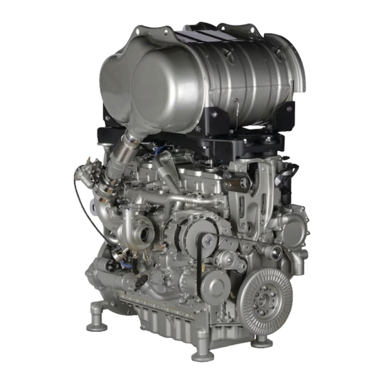
SEBU8732-05 Product Information Section General Information Product Information Section General Information i05192513 Model View Illustrations The following model views show typical features of the engine. Due to individual applications, your engine may appear different from the illustrations. 1206F-E70TA Single Turbocharged Engine with Installed Aftertreatment Illustration 18 g03393436... - Page 23 SEBU8732-05 Product Information Section Model View Illustrations 1206F-E70TTA Engine Views with Series Turbochargers Illustration 19 g03387645 Typical example (1) Rear engine lifting eye (4) Alternator (7) Back pressure valve (2) High-pressure turbocharger (5) Low-pressure turbocharger (3) Front engine lifting eye...
- Page 24 SEBU8732-05 Product Information Section Model View Illustrations Illustration 20 g03387666 Typical example (8) Secondary fuel filter (12) Flywheel housing (17) Oil level gauge (Dipstick) (9) Primary fuel filter (13) Flywheel (18) Oil drain tap (10) Crankcase breather (14) Solenoid for starting motor (19) location for the oil sampling valve (11) Engine Electronic Control Module (15) Starting motor...
- Page 25 SEBU8732-05 Product Information Section Model View Illustrations Illustration 21 g03387667 Typical example (21) NOx Reduction system (NRS) (24) Oil filler cap (27) Crankshaft damper (22) Air intake (25) Water pump (28) Belt tensioner (23) Coolant outlet (26) Coolant intake (29) Belt...
- Page 26 SEBU8732-05 Product Information Section Model View Illustrations Off Engine Components Illustration 22 g03387619 Items that can be supplied loose. (1) Clean emission module (5) NOx sensors (9) Flexible exhaust pipe assembly (2) Pump electronics tank unit (6) In-line fuel filter (9 A) Protection sleeve for flexible exhaust (3) Heated line (7) Priming/tranfer fuel pump...
- Page 27 SEBU8732-05 Product Information Section Model View Illustrations Note: Use the sleeve (9 A) for transportation only. Engine Aftertreatment System Illustration 23 g03027726 Typical example (1) Clean Emission Module (CEM) (3) Exhaust intake connection (5) Diesel Exhaust Fluid (DEF) injector (2) Lifting eyes for CEM (4) Exhaust outlet connection...
- Page 28 1206F-E70TA a single turbocharged use of Diesel Exhaust Fluid (DEF) to be injected into engine. This engine prefix is BM. The 1206F-E70TTA the system in order to lower the emissions from the is a series turbocharged engine and the prefix for this engine.
- Page 29 Counterclockwise desired engine speed. The operating rpm is dependent on the engine rating, the appli- cation, and the configuration of the throttle. Table 2 1206F-E70TTA Series Turbocharged Engine Specifications Operating Range (rpm) 900 to 2800 Number of Cylinders 6 In-Line...
- Page 30 There are three types of diagnostic codes: active, Engines logged and event. Perkins does not warrant the quality or performance Most of the diagnostic codes are logged and stored in of non-Perkins fluids and filters. the ECM. For additional information, refer to the Operation and Maintenance Manual, “Engine...
-
Page 31: Product Identification Information
Plate Locations and Film Locations (Aftertreatment System) Clean Emission Module (CEM) Illustration 26 g03046077 Perkins engines are identified by an engine serial number. An example of an engine number is BN*****U000001J. ***** The list number for the engine Type of engine... - Page 32 Typical example PETU serial plate Record the information on the CEM and PETU serial Pump Electronic Tank Unit (PETU) plates. The information will be required by your Perkins dealer or your Perkins distributor in order to identify replacement part numbers. i05193198 Emissions Certification Film The label for the emission is installed on the front gear cover.
- Page 33 SEBU8732-05 Product Information Section Reference Information Secondary Fuel Filter Element Lubrication Oil Filter Element Auxiliary Oil Filter Element Total Lubrication System Capacity Total Cooling System Capacity Air Cleaner Element Drive Belt Clean Emission Module Part Number Serial Number Pump Electronics Tank Unit Part Number Serial Number Illustration 32...
-
Page 34: Operation Section
SEBU8732-05 Operation Section Lifting and Storage Operation Section Engine and Clean Emission Module (CEM) Lifting and Storage i07432589 Product Lifting NOTICE Always inspect lifting eyebolts and all other lifting equipment for damage before performing any lifting. Never bend the eyebolts and the brackets. Never perform product lifting if components are damaged. - Page 35 SEBU8732-05 Operation Section Product Lifting Illustration 35 g03419909 Typical example (3) Lifting eyes for PETU Refer to illustration 35 for the location of the lifting eyes to lift the PETU. Illustration 34 g03051677 Typical example (2) Lifting eyes for the CEM Refer to illustration 34 for the location of the lifting eyes to lift the CEM.
- Page 36 Product Storage (Engine and Aftertreatment) Perkins are not responsible for damage which may occur when an engine is in storage after a period in service. Your Perkins dealer or your Perkins distributor can assist in preparing the engine for extended storage...
- Page 37 Allow at least 2 minutes after the engine has stopped before you turn the Ensure that the cooling system is filled with Perkins battery disconnect switch to OFF. Disconnecting the ELC, or an antifreeze that meets “ASTM D6210”...
- Page 38 SEBU8732-05 Operation Section Engine and Aftertreatment Removal from Storage DEF has a limited life, refer to table 3 for the time and temperature range. DEF that is outside this range MUST be replaced. On removal from storage the DEF quality in the tank must be tested with a refractometer.
-
Page 39: Features And Controls
SEBU8732-05 Operation Section Features and Controls Features and Controls Intake manifold pressure – The intake manifold pressure sensor checks the rated pressure in the engine manifold. i05416516 Fuel rail pressure – The fuel rail pressure sensor Alarms and Shutoffs measures the high pressure or low pressure in the fuel rail. - Page 40 DEF injector. Any warning should be investigated immediately, contact your Perkins dealer or your Perkins Distributor . The system is equipped with an override NOTICE option. Once the override option has been used and...
- Page 41 SEBU8732-05 Operation Section Selective Catalytic Reduction Warning System • Inducement Engine derates, vehicle speed • At Level 3 cycling the keyswitch will give 20 limits, or other actions intended to prompt the minutes override at full power, before the operator to repair or maintain the emission control shutdown or idle is triggered.
- Page 42 The stop lamp will be on solid Contact your Perkins dealer or your Perkins Distributor at level 1 warning, do not let the fault develop. Table 5 World-Wide Reduced Performance Setting Category 2 Fault (Non-Tampering Dosing and Interruption)
- Page 43 Emission malfunction lamp will be on solid lamp will flash lamp will flash lamp will flash The stop lamp will be on solid Contact your Perkins dealer or your Perkins Distributor at level 1 warning, do not let the fault develop.
- Page 44 The stop lamp will activate Contact your Perkins dealer or your Perkins Distributor at level 1 warning, do not let the fault develop. Table 8 World-Wide Reduced Time Setting Category 2 Fault (Non-Tampering Dosing Interruption)
- Page 45 The stop lamp will activate Contact your Perkins dealer or your Perkins Distributor at level 1 warning, do not let the fault develop. World-Wide DEF Level Warnings Two options are available but only one option will be enabled.
- Page 46 Determine and correct the cause of any significant change in the readings. Consult your Perkins dealer or your Perkins distributor for assistance. Some engine applications are equipped with Indicator Lamps.
- Page 47 3. Inspect the cooling system for leaks. If necessary, consult your Perkins dealer or your Perkins distributor for assistance.
- Page 48 SEBU8732-05 Operation Section Monitoring System The lamps will illuminate for 2 seconds in order to check that the lamps are functioning when the keyswitch is turned to the ON position. If any of the lamps stay illuminated, or a lamp fails to be illuminated the reason should be investigated immediately.
- Page 49 1. One or more of the shutdown values for diagnostic code. the engine protection strategy has been Contact your Perkins dealer or your Perkins exceeded. distributor. 2. A serious active diagnostic code has been detected.
- Page 50 SEBU8732-05 Operation Section Sensors and Electrical Components The default setting for an overspeed is 3000 rpm. The ECM will cut the power to the electronic unit injectors, until the rpm drops below 200 rpm of the overspeed setting. A diagnostic fault code will be logged into the ECM memory and a warning lamp will indicate a diagnostic fault code.
- Page 51 SEBU8732-05 Operation Section Sensors and Electrical Components Engine Components Illustration 41 g03389319 Typical example (1) Coolant Temperature Sensor (6) Inlet Manifold Air Temperature Sensor (13) Primary Speed/Timing Sensor (2) Injector Connector for Number One and (7) Inlet Manifold Air Pressure Sensor (14) Starter Solenoid Two Injectors (8) Glow Plug Connection...
- Page 52 SEBU8732-05 Operation Section Sensors and Electrical Components Illustration 42 g03389322 Typical example (20) Wastegate Regulator (22) Temperature Sensor for the NRS (25) Back Pressure Valve (21) Control Valve for the NOx Reduction (23) Intake Pressure for the NRS System (NRS) (24) Differential Pressure for the NRS...
- Page 53 SEBU8732-05 Operation Section Sensors and Electrical Components Illustration 43 g03389323 Typical example (26) Alternator (27) Secondary Speed/Timing sensor (28) Exhaust Temperature Sensor...
- Page 54 SEBU8732-05 Operation Section Sensors and Electrical Components Illustration 44 g03393046 Typical example (29) Water in Fuel Switch (30) Inlet Air Temperature Some applications do not require a diagnostic connector (9) installed in the engine wiring harness. The Inlet air temperature sensor (30) will be installed in the induction system between the air cleaner and the inlet manifold.
- Page 55 SEBU8732-05 Operation Section Sensors and Electrical Components Illustration 46 g03393011 Typical example (9) Diagnostic connector (10) Electronic Control Module (11) Atmospheric Pressure Sensor (Barometric Pressure sensor) (12) Oil pressure sensor Illustration 47 g03392999 Typical example (13) Primary Speed/Timing Sensor...
- Page 56 SEBU8732-05 Operation Section Sensors and Electrical Components Illustration 48 g03393000 Typical example (14) Starter Solenoid (16) Starter Relay (15) Starting Motor (17) Oil Level Switch Illustration 49 g03393004 Typical example (18) Fuel Temperature Sensor (19) Solenoid for High-Pressure Fuel Pump...
- Page 57 SEBU8732-05 Operation Section Sensors and Electrical Components Illustration 50 g03393005 Typical example (20) Wastegate Regulator (22) Temperature Sensor for the NRS (24) Differential Pressure for the NRS (21) Control Valve for NRS (23) Intake Pressure for the NRS...
- Page 58 SEBU8732-05 Operation Section Sensors and Electrical Components Illustration 51 g03393010 Typical example (25) Back Pressure valve (26) Alternator...
- Page 59 SEBU8732-05 Operation Section Sensors and Electrical Components Illustration 52 g03393006 Typical example (27) Secondary Speed/Timing sensor (28) Exhaust Temperature Sensor Aftertreatment Components...
- Page 60 SEBU8732-05 Operation Section Sensors and Electrical Components Illustration 53 g03393078 Clean Emissions Module (CEM) Illustration 54 g03393624 (1) Clean Emission Module (2) Gas Intake Temperature Sensor (3) Soot Sensor Antenna (4) Location for NOx Sensing Element (5) Soot Sensor Antenna (6) Diesel Exhaust Fluid Injector (7) Temperature Sensor Connector (8) Identification Module...
- Page 61 SEBU8732-05 Operation Section Sensors and Electrical Components Illustration 55 g03393632 (2) Gas Intake Temperature Sensor (4) Location for NOx Sensing Element (6) Diesel Exhaust Fluid Injector (3) Soot Sensor Antenna (5) Soot Sensor Antenna Illustration 56 g03393634 (7) Temperature Sensor Connector (9) Gas Temperature Sensor before (8) Identification Module Selective Catalytic Reduction...
- Page 62 SEBU8732-05 Operation Section Sensors and Electrical Components Soot and NOx Sensors Illustration 57 g03393956 (10) Soot Sensor (11) NOx Sensors The location of the soot sensor (10) and NOx sensor (11) will depend on the application. Pump Electronic Tank Unit (PETU) Illustration 58 g03393959 (1) DEF manifold...
- Page 63 SEBU8732-05 Operation Section Sensors and Electrical Components Note: The DEF manifold (1) contains DEF heater, DEF level sensor, DEF temperature sensor, and DEF quality sensor.
- Page 64 SEBU8732-05 Operation Section Sensors and Electrical Components Heated Line Illustration 59 g03393960 Typical example (7) Heated line...
-
Page 65: Engine Diagnostics
The sequence of flashes represents the system diagnostic message. Count the first sequence of flashes in Perkins Electronic Engines have the capability to order to determine the first digit of the flash code. perform a self-diagnostics test. When the system... - Page 66 SEBU8732-05 Operation Section Engine Operation with Intermittent Diagnostic Codes Note: If the customer has selected “DERATE” and if The electronic service tool is required in order to alter the configuration parameters. there is a low oil pressure condition, the Electronic Control Module (ECM) will limit the engine power System Configuration Parameters until the problem is corrected.
- Page 67 SEBU8732-05 Operation Section Configuration Parameters Table 13 System Configuration Parameters Configuration Parameters Record Engine Serial Number Factory Installed Aftertreatment #1 Identification Number DPF #1 Soot Loading Sensing System Configuration Code Limp Home Engine Speed Ramp Rate System Operating Voltage Configuration Rating Number CAN Communication Protocol Write Security Engine Emissions Operator Inducement Progress Configuration...
- Page 68 SEBU8732-05 Operation Section Configuration Parameters (Table 14, contd) Engine Idle Shutdown Delay Time Engine Idle Shutdown Ambient Temperature Override Enable Status High Soot Load Aftertreatment Protection Enable Status Air Shutoff Throttle Lock Feature Installation Status PTO Mode Throttle Lock Engine Set Speed #1 Throttle Lock Engine Set Speed #2 Throttle Lock Increment Speed Ramp Rate Throttle Lock Decrement Speed Ramp Rate...
- Page 69 SEBU8732-05 Operation Section Configuration Parameters (Table 14, contd) Engine Cooling Fan Maximum Air Flow Coolant Temperature Engine Cooling Fan Minimum Air Flow Coolant Temperature Engine Cooling Fan Control Transmission Oil Temperature Input Enable Status Engine Cooling Fan Maximum Air Flow Transmission Oil Temperature Engine Cooling Fan Minimum Air Flow Transmission Oil Temperature Engine Cooling Fan Control Hydraulic Oil Temperature Input Enable Status Engine Cooling Fan Maximum Air Flow Hydraulic Oil Temperature...
-
Page 70: Engine Starting
SEBU8732-05 Operation Section Engine Starting Engine Starting i05360375 Cold Weather Starting i04935860 Before Starting Engine Do not use aerosol types of starting aids such as Perform the required daily maintenance and other ether. Such use could result in an explosion and periodic maintenance before the engine is started. - Page 71 SEBU8732-05 Operation Section Starting the Engine 5. Repeat step 2 through step 4 if the engine fails to Note: The operating period of the warning light for the glow plugs will change due to the temperature of start. the engine. Note: After starting, the engine may be held at low speed for a duration between 1 and 25 seconds to NOTICE...
- Page 72 SEBU8732-05 Operation Section After Starting Engine 5. Immediately after the engine is started, disconnect the jump-start cables in reverse order. Improper jump start cable connections can cause After jump starting, the alternator may not be able to an explosion resulting in personal injury. recharge fully batteries that are severely discharged.
-
Page 73: Engine Operation
SEBU8732-05 Operation Section Engine Operation Engine Operation The DPF may require the exhaust gas temperature to rise in order to remove the soot. If necessary, the back pressure valve operates in order to create the rise in temperature. In some applications, the i04907268 operation of the back pressure valve will make the Engine Operation... - Page 74 Fuel Conservation Practices The efficiency of the engine can affect the fuel economy. Perkins design and technology in manufacturing provides maximum fuel efficiency in all applications. Follow the recommended procedures in order to attain optimum performance for the life of the engine.
-
Page 75: Cold Weather Operation
Perkins Diesel Engines can operate effectively in cold weather. During cold weather, the starting and • Install the correct specification of engine lubricant the operation of the diesel engine is dependent on before the beginning of cold weather. - Page 76 For these reasons, when the engine is started, the 240 V dc. The output can be 750/1000W. Consult engine must be operated until the coolant your Perkins dealer or your Perkins distributor for temperature is 80° C (176° F) minimum. Carbon more information.
- Page 77 SEBU8732-05 Operation Section Radiator Restrictions The Water Temperature Regulator and Consult with your Perkins dealer or your Perkins distributor for the recommended breather Insulated Heater Lines components for operation from −25° to -40°C (−13° to -72.°F). The engine is equipped with a water temperature regulator.
- Page 78 SEBU8732-05 Operation Section Fuel Related Components in Cold Weather Properties of the diesel fuel can have a significant i05359588 effect on the engine cold start capability. It is critical Fuel Related Components in that the low temperature properties of diesel fuel are acceptable for the minimum ambient temperature the Cold Weather engine is expected to see in the operation.
- Page 79 SEBU8732-05 Operation Section Diesel Exhaust Fluid in Cold Weather For more information about fuel heaters (if equipped), refer to the OEM information. i05769085 Diesel Exhaust Fluid in Cold Weather Due to the freezing point of Diesel Exhaust Fluid (DEF) the aftertreatment system is equipped with electrically heated DEF lines.
-
Page 80: Engine Stopping
SEBU8732-05 Operation Section Engine Stopping Engine Stopping Note: There may be regulations that define the requirements for the operator and/or support personnel to be present when the engine is running. i05406628 Stopping the Engine Leaving the machine unattended when the engine is running may result in personal injury or death. - Page 81 SEBU8732-05 Operation Section After Stopping Engine • Allow the engine to cool. Check the coolant level. • Check the coolant for correct antifreeze protection Contact with high pressure fuel may cause fluid and the correct corrosion protection. Add the penetration and burn hazards. High pressure fuel correct coolant/water mixture, if necessary.
-
Page 82: Maintenance Section
This conversion will reduce the emission of the Specifications. engine. Table 15 Specification Engine Refill Capacities DEF that is used in Perkins engines must meet the Compartment or System Minimum Maximum ISO specification 22241-1 for quality. The ISO specification 22241-1 requirements are met by many 13.5 L 16.5 L... - Page 83 • SAE Society Of Automotive Engineers Inc. • ACEA Association des Constructers Perkins recommend that all DEF taken from storage European Automobiles. should be checked to ensure the DEF meets ISO standard 22241-1. • ECF-3 Engine Crankcase Fluid...
- Page 84 Use oil “EMA Recommended Guideline on Diesel Engine analysis also to determine the oil change interval that Oil”. In addition to Perkins definitions, there are other is optimum. definitions that will be of assistance in purchasing lubricants.
- Page 85 Aftermarket Oil Additives allows technicians to determine the amount of deterioration of the oil during use. This analysis Perkins does not recommend the use of aftermarket also allows technicians to verify the performance additives in oil. The use of aftermarket additives is...
- Page 86 Contact your local Perkins distributor for the most up-to-date recommendations. Diesel Fuel Requirements Perkins is not in a position to continuously evaluate and monitor all worldwide distillate diesel fuel specifications that are published by governments and technological societies.
- Page 87 SEBU8732-05 Maintenance Section General Fuel Information Table 19 "Perkins Specification for Distillate Diesel Fuel" Property UNITS Requirements “ASTM”Test “ISO/Other”Test Aromatics %Volume 35% maximum “D1319” “ISO 3837” %Weight 0.01% maximum “D482” “ISO 6245” Carbon Residue on 10% %Weight 0.35% maximum “D524”...
- Page 88 “BS 2869: 2010 CLASS A2 or EU equivalent” “EU Off-Road Diesel fuel. Acceptable from 2011 MUST have less than 10 PPM sulfur level” All the fuels must comply with the specification in the table for the Perkins Specification Distillate Diesel Fuel.
- Page 89 CFR engine. (59 °F). Refer to “ISO 5165” for the test method. Perkins recommends a density of 841 kg/m Cetane numbers more than 45 are normally expected obtain the correct power output. Lighter fuels are from current diesel fuel. However, a cetane number acceptable but these fuels will not produce the rated of 40 may be experienced in some territories.
- Page 90 0.52 mm (0.0205 inch) will Protection Agency (EPA) and European Certification lead to reduced service life and premature failure of fuels. Perkins does not certify engines on any other the fuel system. fuel. The user of the engine has the responsibility of using the correct fuel that is recommended by the Fuel additives can enhance the lubricity of a fuel.
- Page 91 Test should include acid number • Perkins recommend the use of oil analysis to (EN14104), oxidation stability (EN 15751 commonly check the quality of the engine oil if biodiesel fuel know as the Rancimant test), and sediment is used.
- Page 92 “Operation and Maintenance Manual” Fluid Recommendations If biodiesel or biodiesel blends of fuel are to be used, Perkins require the use of Perkins fuel cleaner. The Fuel for Cold-Weather Operation use of the fuel is to remove deposits within the fuel system that is created with the use of biodiesel.
- Page 93 Never add coolant to an overheated engine. Engine damage could result. Allow the engine to cool first. • Perkins recommends the use of bulk fuel filter / coalescer units which clean the fuel of both particulate contamination and water in a single...
- Page 94 SEBU8732-05 Maintenance Section Fluid Recommendations Table 21 NOTICE If the engine is to be stored in, or shipped to an area Acceptable Water with below freezing temperatures, the cooling system Property Maximum Limit must be either protected to the lowest outside tem- perature or drained completely to prevent damage.
- Page 95 American Society for Testing and • Heavy-duty diesel engines Materials • Automotive applications The following two coolants are used in Perkins diesel engines: The anti-corrosion package for ELC is different from the anti-corrosion package for other coolants. ELC is Preferred – Perkins ELC an ethylene glycol base coolant.
- Page 96 Perkins ELC and operate the engine (SCA). ensure that the thermostat opens. Stop the engine and allow to cool. When using Perkins ELC, do not use standard SCA's or SCA filters. 5. Drain the cooling system. NOTICE ELC Cooling System Cleaning...
- Page 97 SCA that is required when the cooling ness of the ELC and shortens the ELC service life. system is initially filled. Use only Perkins Products for premixed or concen- trate coolants. Failure to follow these recommenda- Table 25...
- Page 98 SEBU8732-05 Maintenance Section Fluid Recommendations Table 28 Example Of The Equation For Adding The SCA To The Heavy- Duty Coolant For Maintenance Total Volume of the Multiplication Amount of SCA Cooling System (V) Factor that is Required 15 L (4 US gal) ×...
-
Page 99: Maintenance Recommendations
The engine can have the ability to auto start. Ensure a chassis frame or rail. Consult the OEM of the equip- that the power supply is isolated before any service ment or your Perkins dealer regarding welding on a or repair is performed. chassis frame or rail. - Page 100 SEBU8732-05 Maintenance Section Welding on Engines with Electronic Controls 4. Disconnect all electronic components from the wiring harnesses. Include the following components: • Electronic components for the driven equipment • ECM • Sensors • Electric operated fuel pump • Electronically controlled valves •...
- Page 101 • The temperature of the fluid in the engine coolant/antifreeze Refer to the standards for the engine or consult your Perkins distributor to determine if the engine is operating within the defined parameters. Severe service operation can accelerate component wear. Engines that operate under severe conditions...
-
Page 102: Maintenance Interval Schedule
SEBU8732-05 Maintenance Section Maintenance Interval Schedule “ Engine Air Cleaner Element - Replace” ..118 i07229305 Maintenance Interval Schedule “ Fuel Filter (In-Line) - Replace” ....128 “... - Page 103 SEBU8732-05 Maintenance Section Maintenance Interval Schedule “ Injector (Diesel Exhaust Fluid) - Replace” ..135 Every 6000 Service Hours or 3 Years “ Coolant Extender (ELC) - Add” ....110 Every 10 000 Service Hours “...
-
Page 104: Battery - Replace
Aftercooler Core - Clean/Test Alternator - Inspect (Air-To-Air Aftercooler) Perkins recommends a scheduled inspection of the alternator. Inspect the alternator for loose The air-to-air aftercooler is OEM installed in many connections and correct battery charging. Check the applications. Please refer to the OEM specifications ammeter (if equipped) during engine operation in for information that is related to the aftercooler. -
Page 105: Battery Or Battery Cable - Disconnect
SEBU8732-05 Maintenance Section Battery Electrolyte Level - Check The battery cables or the batteries should not be All lead-acid batteries contain sulfuric acid which can burn the skin and clothing. Always wear a removed with the battery cover in place. The bat- face shield and protective clothing when working tery cover should be removed before any servic- on or near batteries. -
Page 106: Belt Tensioner - Check
SEBU8732-05 Maintenance Section Belt - Inspect 2. Disconnect the negative battery terminal. Ensure • Inspect the belt for cracks, splits, glazing, grease, displacement of the cord and evidence of fluid that the cable cannot contact the terminal. When contamination. four 12 V batteries are involved, 2 negative connections must be disconnected. -
Page 107: Coolant (Deac) - Change
SEBU8732-05 Maintenance Section Coolant (DEAC) - Change i05197133 Coolant (DEAC) - Change • DEAC Diesel Engine Antifreeze Coolant Clean the cooling system and flush the cooling system before the recommended maintenance interval if the following conditions exist: • The engine overheats frequently. •... - Page 108 1. Flush the cooling system with clean water and a 1. Fill the cooling system with the coolant/antifreeze. suitable cleaning agent in order to remove any debris. Refer to your Perkins dealer or distributor Refer to this Operation and Maintenance Manual, for suitable cleaning agents.
- Page 109 Coolant (ELC) - Change NOTICE Perkins ELC must be using with an extender in order to achieve 12000 hours operation. For more informa- tion on a suitable extender contact your Perkins deal- er or Perkins distributor.
-
Page 110: Coolant Level - Check
Allow the water to drain. Flush the cooling system with In order for Perkins ELC to achieve 12000 hours an clean water. Install the connection hose. extender must be added at 6000 hours. For a suitable extender, contact your Perkins dealer or 6. -
Page 111: Def Filler Screen - Clean
SEBU8732-05 Maintenance Section Crankshaft Vibration Damper - Inspect i03634651 NOTICE When any servicing or repair of the engine cooling Crankshaft Vibration Damper - system is performed, the procedure must be per- formed with the engine on level ground. This proce- Inspect dure will allow you to check accurately the coolant level. - Page 112 SEBU8732-05 Maintenance Section DEF Manifold Filters - Replace i06940972 DEF Manifold Filters - Replace NOTICE Ensure that the engine is stopped before any servic- ing or repair is performed. NOTICE Care must be taken to ensure that Diesel Exhaust Fluid (DEF) for the system are contained during per- formance of inspection, maintenance, testing, adjust- ing, and repair of the product.
- Page 113 SEBU8732-05 Maintenance Section DEF Manifold Filters - Replace Illustration 74 g03806578 Illustration 75 g03806580 2. Remove band clamp (2) from filter base (1). 3. Remove filter (3) from filter base (1).
- Page 114 SEBU8732-05 Maintenance Section DEF Manifold Filters - Replace Illustration 76 g03806581 Illustration 78 g06159487 1. Note the location of clamp (2). The clamp (2) must be between the marked location (A). 2. Loosen clamp (2) and remove outer filter (3) from DEF tank header (1) and discard outer filter (3).
-
Page 115: Diesel Exhaust Fluid - Fill
SEBU8732-05 Maintenance Section Diesel Exhaust Fluid - Fill 6. Install the retaining plate (6) and install screws (7). Tighten screws (7) to a torque of 1.1 N·m (9.8 lb in). 7. Install new outer filter (3) onto DEF tank header (1). -
Page 116: Diesel Exhaust Fluid Filter - Replace
SEBU8732-05 Maintenance Section Diesel Exhaust Fluid Filter - Replace 4. The opening on the DEF tank (2) is a special diameter. Ensure that the correct nozzle is used when filling the DEF tank. 5. Check the cleanliness of DEF cap and install the DEF cap. -
Page 117: Diesel Exhaust Fluid Tank - Flush
SEBU8732-05 Maintenance Section Diesel Exhaust Fluid Tank - Flush i06730803 Diesel Exhaust Fluid Tank - Flush Illustration 83 g06215916 Typical example 3. Use supplied tool (5) to remove filter element (2) from DEF pump assembly (1). 4. Install new filter element (2) into DEF pump assembly (1). -
Page 118: Engine - Clean
If the DEF tank has been fill with another fluid other rear of the connectors. Avoid electrical components than DEF, then contact your Perkins distributor. such as the alternator, the starter, and the ECM. Protect the fuel injection pump from fluids to wash the i02151646 engine. - Page 119 Engine Air Cleaner Element - Replace Servicing the Air Cleaner Elements Note: The air filter system may not have been provided by Perkins. The procedure that follows is for a typical air filter system. Refer to the OEM information for the correct procedure.
-
Page 120: Engine Air Cleaner Service Indicator - Inspect
SEBU8732-05 Maintenance Section Engine Air Cleaner Service Indicator - Inspect 6. Install end cover (4) to air cleaner body (2) and • Check the movement of the yellow core when the engine is accelerated to the engine rated speed. secure end cover. If necessary, reset the air The yellow core should latch at the greatest service indicator, refer to this Operation and vacuum that is attained. -
Page 121: Replace
Description”. Within that section, refer to the title Place a container under the breather assembly. “Aftermarket Products and Perkins Engines”. 2. Rotate the top cap (1) counterclockwise into the The breather element can be serviced from the top unlocked position. - Page 122 SEBU8732-05 Maintenance Section Engine Crankcase Breather Element - Replace 4. Install a new filter element into the breather body (3). Ensure the correct position of the element, refer to illustration 90 . Align position (A) on the top cap to position (B) on the filter element. Illustration 89 g03090963 3.
- Page 123 SEBU8732-05 Maintenance Section Engine Crankcase Breather Element - Replace Illustration 92 g02346498 Typical example (X) Alignment mark (Y) Alignment mark 1. Ensure that the outside body of the breather assembly is clean and free from damage. Place a Illustration 93 g03090968 container under the breather.
-
Page 124: Engine Oil Level - Check
Note: The engine mounts may not have been supplied by Perkins. Refer to the OEM information for 1. Maintain the oil level between the mark (L) and the further information on the engine mounts and the mark (H) on the engine oil dipstick. -
Page 125: Engine Oil Sample - Obtain
Perkins recommends using a sampling valve in order Hot oil and hot components can cause personal to obtain oil samples. The quality and the consistency injury. - Page 126 Engine Oil sample - Obtain for more information. cations. Use of an oil filter that is not recommended by Perkins could result in severe damage to the en- If the engine is operated infrequently less than 500 gine bearings, crankshaft, and so forth. As a result of...
-
Page 127: Fan Clearance - Check
SEBU8732-05 Maintenance Section Fan Clearance - Check 2. Start the engine and run the engine at “LOW IDLE” for 2 minutes. Perform this procedure to ensure that the lubrication system has oil and that the oil filters are filled. Inspect the oil filter for oil leaks. 3. -
Page 128: Fuel Filter (In-Line) - Replace
SEBU8732-05 Maintenance Section Fuel Filter (In-Line) - Replace Illustration 99 g03414037 Typical example The gap (A) must be checked in the vertical position i05814842 and in the horizontal position. Fuel Filter (In-Line) - Replace In the vertical position the gap can be checked at the vertically top position or at the vertically bottom position. -
Page 129: Fuel System - Prime
SEBU8732-05 Maintenance Section Fuel System - Prime i05774864 NOTICE Ensure that the engine is stopped before any servic- Fuel System - Prime ing or repair is performed. The location of the in-line fuel filter will depend on the application that the engine has been installed. Note: Refer to Systems Operation, Testing, and Adjusting, “Cleanliness of Fuel System Components”... -
Page 130: Fuel System Primary Filter (Water Separator)
SEBU8732-05 Maintenance Section Fuel System Primary Filter (Water Separator) Element - Replace After the engine has stopped, you must wait for 10 minutes in order to allow the fuel pressure to be purged from the high-pressure fuel lines before any service or repair is performed on the engine fuel lines. - Page 131 SEBU8732-05 Maintenance Section Fuel System Primary Filter (Water Separator) Element - Replace 9. Rotate the filter element (5) counterclockwise and remove the filter element . Clean the filter bowl. Install the New Filter Element Illustration 102 g03858640 Typical example Illustration 103 g03086798 Typical example 1.
-
Page 132: Fuel System Primary Filter/Water Separator - Drain
SEBU8732-05 Maintenance Section Fuel System Primary Filter/Water Separator - Drain 5. The secondary filter element must be replaced at the same time as the primary filter element. Also, the in-line filter must be changed. Refer to the Operation and Maintenance Manual , “Fuel System Filter - Replace”. - Page 133 SEBU8732-05 Maintenance Section Fuel System Secondary Filter - Replace Refer to Systems Operation, Testing, and Adjusting, “Cleanliness of Fuel System Components” for detailed information on the standards of cleanliness that must be observed during ALL work on the fuel system. Remove the Element 1.
-
Page 134: Hoses And Clamps - Inspect/Replace
SEBU8732-05 Maintenance Section Fuel Tank Water and Sediment - Drain 3. Do not use a tool in order to install the filter Open the drain valve on the bottom of the fuel tank in order to drain the water and the sediment. Close the assembly. - Page 135 SEBU8732-05 Maintenance Section Injector (Diesel Exhaust Fluid) - Replace Inspect all hoses for leaks that are caused by the following conditions: Pressurized System: Hot coolant can cause seri- • Cracking ous burns. To open the cooling system filler cap, stop the engine and wait until the cooling system •...
-
Page 136: Radiator - Clean
Repeat the cleaning, if necessary. Inspect the fins for damage. Bent fins may be opened The radiator is not usually supplied by Perkins. The with a “comb”. Inspect these items for good condition: following text describes a typical cleaning procedure Welds, mounting brackets, air lines, connections, for the radiator. -
Page 137: Turbocharger - Inspect
SEBU8732-05 Maintenance Section Turbocharger - Inspect Engine Installed with Single i04922217 Turbocharger Turbocharger - Inspect Hot engine components can cause injury from burns. Before performing maintenance on the en- gine, allow the engine and the components to cool. NOTICE Turbocharger bearing failures can cause large quan- tities of oil to enter the air intake and exhaust sys- tems. -
Page 138: Walk-Around Inspection
SEBU8732-05 Maintenance Section Walk-Around Inspection 5. Install the air intake pipe and the exhaust outlet 4. Check for obvious heat discoloration of the pipe to the turbocharger housing. Ensure that all turbocharger. Check for any loose bolts or any clamps are installed correctly and that all clamps missing bolts. - Page 139 Remove and Install”. For more information, consult clean fuel enters the fuel system. your Perkins dealer or your Perkins distributor. • Inspect the wiring and the wiring harnesses for • Inspect the lubrication system for leaks at the front...
-
Page 140: Water Pump - Inspect
SEBU8732-05 Maintenance Section Water Pump - Inspect • Inspect the ground strap for a good connection and for good condition. • Disconnect any battery chargers that are not protected against the current drain of the starting motor. Check the condition and the electrolyte level of the batteries, unless the engine is equipped with a maintenance free battery. -
Page 141: Warranty Section
(“emission-related components”), are: For a detailed explanation of the Emission Control Warranty, contact your authorized Perkins dealer or a. Designed, built, and equipped so as to conform, your authorized Perkins distributor. at the time of sale, with applicable emission... -
Page 142: Reference Information Section
Maintenance records are a key element of a maintenance program that is correctly managed. Accurate maintenance records can help your Perkins dealer to fine-tune the recommended maintenance intervals in order to meet the specific operating situation. This should result in a lower engine operating cost. - Page 143 SEBU8732-05 Reference Information Section Maintenance Log i05204675 Maintenance Log Table 29 Engine Model Customer Identifier Arrangement Number Serial Number Service Quantity Of Service Item Date Authorization Hours Fuel...
- Page 144 Why buy an Extended Service Contract? 1. No surprises - total protection from unexpected repair cost (parts, labor, and travel). 2. Enjoy longer lasting product support from Perkins global network. 3. Genuine Perkins parts ensure continued engine performance. 4. Highly trained technicians carry out all repairs.
-
Page 145: Index
SEBU8732-05 Index Section Index Flush ............110 Coolant Extender (ELC) - Add .......110 After Starting Engine ........72 Coolant Level - Check ........110 After Stopping Engine ........80 Crankshaft Vibration Damper - Inspect..111 Aftercooler Core - Clean/Test (Air-To-Air Viscous Damper ......... 111 Aftercooler) .......... - Page 146 SEBU8732-05 Index Section Replace the Oil Filter ......... 126 Fuel Tanks ........... 78 Engine Oil Level - Check....... 124 Fuel System - Prime........129 Engine Oil Sample - Obtain......125 Fuel System Primary Filter (Water Obtain the Sample and the Analysis ..125 Separator) Element - Replace.....
- Page 147 Reference Material (Extended Service 1206F-E70TA Single Turbocharged Engine Contract)............144 with Installed Aftertreatment ...... 22 Reference Materials ........142 1206F-E70TTA Engine Views with Series Refill Capacities..........82 Turbochargers..........23 Cooling System..........82 Engine Aftertreatment System ....27 Lubrication System ........82 Off Engine Components ......
- Page 148 SEBU8732-05 Index Section Starting the Engine ........71 Starting with Jump Start Cables (Do Not Use This Procedure in Hazardous Locations that have Explosive Atmospheres) ..........71 Stopping the Engine ........80 Delayed Engine Shutdown (if Equipped) ..80 System Pressure Release....... 99 Coolant System ...........
- Page 149 Product and Dealer Information Note: For product identification plate locations, see the section “Product Identification Information” in the Operation and Maintenance Manual. Delivery Date: Product Information Model: Product Identification Number: Engine Serial Number: Transmission Serial Number: Generator Serial Number: Attachment Serial Numbers: Attachment Information: Customer Equipment Number: Dealer Equipment Number:...
- Page 150 SEBU8732 ©2018 Perkins Engines Company Limited All Rights Reserved June 2018...