
Related Manuals for Perkins 1204E-E44TA


Summary of Contents for Perkins 1204E-E44TA
- Page 1 SEBU8605-01 May 2011 Operation and Maintenance Manual 1204E-E44TA and 1204E-E44TTA Industrial Engines MK (Engine) ML (Engine)
-
Page 2: Important Safety Information
These changes can affect the service that is given to the product. Obtain the complete and most current information before you start any job. Perkins dealers or Perkins distributors have the most current information available. When replacement parts are required for this product Perkins recommends using Perkins replacement parts. -
Page 3: Table Of Contents
SEBU8605-01 Table of Contents Table of Contents Maintenance Interval Schedule ......80 Warranty Section Foreword ..............4 Warranty Information ........... 113 Safety Section Reference Information Section Safety Messages ............ 5 Reference Materials ..........117 General Hazard Information ........7 Index Section Burn Prevention ............ -
Page 4: Foreword
They assist with developing the skills and Perkins authorized personnel. Your Perkins dealer techniques required to operate the engine more or your Perkins distributor offers a variety of options efficiently and economically. Skill and techniques regarding overhaul programs. If you experience... -
Page 5: Safety Section
Replace any warning sign that is damaged or missing. If a warning sign is attached to a part of the engine that is replaced, install a new warning sign on the replacement part. Your Perkins distributor can provide new warning signs. (1) Universal Warning... - Page 6 SEBU8605-01 Safety Section Safety Messages g02406137 Illustration 2 (1) Universal Warning (2) Hand (High Pressure) Contact with high pressure fuel may cause fluid penetration and burn hazards. High pressure fu- el spray may cause a fire hazard. Failure to fol- low these inspection, maintenance and service in- structions may cause personal injury or death.
-
Page 7: General Hazard Information
SEBU8605-01 Safety Section General Hazard Information g01154809 Illustration 5 Typical example i03566024 General Hazard Information g02406178 Illustration 4 (2) Hand (High Pressure) The warning label for the Hand (High Pressure) (2) is a wrap around label that is installed on the high-pressure fuel line. - Page 8 SEBU8605-01 Safety Section General Hazard Information • • If the engine is not running, do not release the For initial start-up of a new engine or for starting an secondary brake or the parking brake systems engine that has been serviced, make provisions to unless the vehicle is blocked or unless the vehicle stop the engine if an overspeed occurs.
-
Page 9: Containing Fluid Spillage
SEBU8605-01 Safety Section General Hazard Information • Do not wear loose clothing or jewelry that can snag on controls or on other parts of the engine. • Ensure that all protective guards and all covers are secured in place on the engine. •... -
Page 10: Burn Prevention
Dispose of Waste Properly Perkins replacement parts that are shipped from Perkins are asbestos free. Perkins recommends the use of only genuine Perkins replacement parts. Use the following guidelines when you handle any replacement parts that contain asbestos or when you handle asbestos debris. -
Page 11: Fire Prevention And Explosion Prevention
If the application involves the presence of combustible Oils gases, consult your Perkins dealer and/or your Perkins distributor for additional information about Hot oil and hot lubricating components can cause suitable protection devices. - Page 12 SEBU8605-01 Safety Section Fire Prevention and Explosion Prevention Store fuels and lubricants in correctly marked containers away from unauthorized persons. Store oily rags and any flammable materials in protective containers. Do not smoke in areas that are used for storing flammable materials. Do not expose the engine to any flame.
-
Page 13: Crushing Prevention And Cutting Prevention
Before objects are struck, ensure that no one will be injured by flying debris. Leaks can cause fires. Consult your Perkins dealer or your Perkins distributor for replacement parts. i04016709 Replace the parts if any of the following conditions... - Page 14 SEBU8605-01 Safety Section High Pressure Fuel Lines g02067853 Illustration 14 (1) High-pressure line (4) High-pressure line (7) Fuel transfer line that is high pressure (2) High-pressure line (5) High-pressure fuel manifold (rail) (3) High-pressure line (6) High-pressure line The high-pressure fuel lines are the fuel lines that Do not loosen the high-pressure fuel lines in order are between the high-pressure fuel pump and the to remove air from the fuel system.
-
Page 15: Before Starting Engine
These engines are equipped with a glow plug starting aid in each individual cylinder that heats the intake air in order to improve starting. Some Perkins engines may have a cold starting system that is controlled by the ECM that allows a controlled flow of ether into the engine. -
Page 16: Engine Stopping
SEBU8605-01 Safety Section Engine Stopping Grounding Practices i02234873 Engine Stopping Stop the engine according to the procedure in the Operation and Maintenance Manual, “Engine Stopping (Operation Section)” in order to avoid overheating of the engine and accelerated wear of the engine components. Use the Emergency Stop Button (if equipped) ONLY in an emergency situation. -
Page 17: Engine Electronics
Note: Many of the engine control systems and display or the OEM wiring installation can be dangerous modules that are available for Perkins Engines will and could result in personal injury or death and/or work in unison with the Engine Monitoring System. -
Page 18: Product Information Section
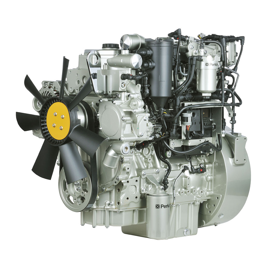
SEBU8605-01 Product Information Section Model Views Product Information Section Model Views i04231649 Model View Illustrations The following model views show typical features of the engine and the aftertreatment system. Due to individual applications, your engine, or your aftertreatment may appear different from the illustrations. - Page 19 SEBU8605-01 Product Information Section Model Views g02409512 Illustration 18 (14) Rear lifting eye (18) Starting motor (22) Flywheel (15) High-pressure turbocharger (19) Oil drain plug (23) NRS cooler (16) Low-pressure turbocharger (20) Exhaust outlet (17) Back pressure valve (21) Flywheel housing...
- Page 20 SEBU8605-01 Product Information Section Model Views g02409862 Illustration 19 (24) Belt (27) Thermostat housing (30) Crankshaft pulley (25) Air intake (28) Water pump (31) Belt tensioner (26) Coolant outlet connection (29) Coolant inlet connection (32) Alternator...
- Page 21 SEBU8605-01 Product Information Section Model Views 1204E-E44TA g02407436 Illustration 20 (1) Front lifting eye (5) Primary fuel filter (9) Oil filter (2) Crankcase breather (6) Fuel priming pump (10) Oil sampling valve (3) NOx reduction system (NRS) (7) Fuel strainer (11) High-pressure fuel pump (4) Secondary fuel filter...
- Page 22 SEBU8605-01 Product Information Section Model Views g02407536 Illustration 21 (12) Rear lifting eye (16) Oil drain valve (20) Flywheel (13) Oil gauge (dipstick) (17) Oil drain plug (21) Exhaust outlet (14) Turbocharger (18) Back pressure valve (22) NRS cooler (15) Starting motor (19) Flywheel housing...
- Page 23 SEBU8605-01 Product Information Section Model Views g02407537 Illustration 22 (23) Oil filler (27) Water pump (31) Alternator (24) Air intake (28) Coolant intake connector (32) Belt (25) Outlet connection for coolant (29) Rear lifting eye (26) Thermostat housing (30) Belt tensioner...
-
Page 24: Engine Description
1 cylinder is the front cylinder. • 1204E-E44TA (MK) • 1204E-E44TTA (ML) The 1204E-E44TA (MK) engine is equipped with a single turbocharger. The 1204E-E44TTA (ML) engine is equipped with series turbochargers. An engine that is equipped with series turbochargers have a low-pressure turbocharger and a high-pressure turbocharger. -
Page 25: Electronic Engine Features
(B) Inlet valves • System diagnostics Table 1 • Aftertreatment low temperature regeneration 1204E-E44TA and 1204E-E44TTA Engine Specifications For more information on electronic engine features, Operating Range (rpm) 800 to 2200 refer to the Operation and Maintenance Manual, “Features and Controls” topic (Operation Section). -
Page 26: Aftertreatment System
flow of lubrication oil to Engines the engine if the oil filter element should become plugged. Perkins does not warrant the quality or performance of non-Perkins fluids and filters. Engine efficiency, efficiency of emission controls, and engine performance depend on adherence to proper When auxiliary devices, accessories, or consumables operation and maintenance recommendations. -
Page 27: Product Identification Information
This information will be required by your depending on the application. Perkins distributor. The information is essential in order to be emissions complaint. g02109493 Illustration 26 Module Arrangement Exhaust Plate... -
Page 28: Reference Numbers
Illustration 27 Information for the following items may be needed to order parts. Locate the information for your engine. Perkins engines are identified by an engine serial Record the information in the appropriate space. number. Make a copy of this list for a record. Keep the information for future reference. -
Page 29: Emissions Certification Film
SEBU8605-01 Product Information Section Product Identification Information Drive Belt _________ ___________________________________________ Engine Aftertreatment System Part Number _________ _______________________________________ Serial Number _________ _____________________________________ i04274850 Emissions Certification Film An emission label is installed on the front gear cover. Note: A second emission label will be supplied with the engine. -
Page 30: Operation Section
Product Lifting fixtures obsolete. If alterations are made, ensure (Engine) that correct lifting devices are provided. Consult your Perkins dealer or your Perkins distributor for information regarding fixtures for correct engine lifting. g01097527 Illustration 30 NOTICE Never bend the eyebolts and the brackets. - Page 31 SEBU8605-01 Operation Section Lifting and Storage Industrial Open Power Unit g02488437 Illustration 31 Typical example (1) Location of front lifting eye (2) Location of rear lifting eye...
-
Page 32: Condition For Storage
The engine must be stored in a water proof building. The building must be kept at a constant temperature. Engines that are filled with Perkins ELC will have coolant protection to an ambient temperature of −36° C (−32.8° F). The engine must not be subjected to extreme variations in temperature and humidity. - Page 33 Operation Section Lifting and Storage 4. Remove the drive belt from the engine. Sealed Coolant System Ensure that the cooling system is filled with Perkins ELC, or an antifreeze that meets “ASTM D6210” specification. Open Cooling System Ensure that all cooling drain plugs have been opened.
-
Page 34: Gauges And Indicators
Determine and correct the cause of any significant If the engine is operating above the normal range, change in the readings. Consult your Perkins reduce the engine load. If high coolant temperatures distributor for assistance. -
Page 35: Indicator Lamps
SEBU8605-01 Operation Section Gauges and Indicators • Oil pressure Service Hour Meter – The gauge indicates • total operating hours of the engine. Intake temperature • Intake pressure Indicator Lamps • Atmospheric pressure There is four indicator lamps that are available. •... -
Page 36: Features And Controls
SEBU8605-01 Operation Section Features and Controls Features and Controls Programmable Options and Systems Operation i04340829 Monitoring System If the Warning/Derate/Shutdown mode has been selected and the warning indicator activates, bring the engine to a stop whenever possible. De- pending on the application, special precautions should be taken to avoid personal injury. - Page 37 Maintenance Manual, “ Monitoring System (Table for Indicator Lamps)”. For each of the programmed modes, refer to Troubleshooting Guide, “Indicator Lamps” for more information on Indicator Lamps. For more information or assistance for repairs, consult your Perkins distributor or your Perkins dealer.
-
Page 38: Monitoring System
SEBU8605-01 Operation Section Features and Controls i04201172 Monitoring System (Table for the Indicator lamps) Note: When in operation the amber warning lamp has three states, solid, flashing, and fast flashing. The sequence is to give a visual indication of the importance of the warning. - Page 39 SEBU8605-01 Operation Section Features and Controls i04215952 Sensors and Electrical Components (Aftertreatment) The illustration within the section shows the typical locations of the sensors and other electrical components on the industrial engine. Specific engine aftertreatment systems may appear different due to the application.
- Page 40 SEBU8605-01 Operation Section Features and Controls g02411637 Illustration 34 (1) Coolant Temperature Sensor (7) Primary Speed/Timing sensor (13) Inlet Pressure Sensor for the NOx (2) Fuel Pressure Sensor (Fuel Rail (Crankshaft Position Sensor) Reduction System (NRS) Pressure Sensor) (8) Diagnostic Connector (14) Outlet Pressure Sensor for the NRS (3) Intake Manifold Air Temperature Sensor (9) Oil Pressure Sensor...
- Page 41 SEBU8605-01 Operation Section Features and Controls g02411837 Illustration 35 (17) Back Pressure Valve (19) Secondary Speed/Timing Sensor (21) Water in Fuel Switch (18) Alternator (Camshaft Position Sensor) (22) Oil Level Switch (if Equipped) (20) Starting Motor (23) Electric Priming Pump g02413838 Illustration 36 (1) Coolant Temperature Sensor...
- Page 42 SEBU8605-01 Operation Section Features and Controls g02413839 Illustration 37 (6) Atmospheric Pressure Sensor (7) Primary Speed/Timing sensor (8) Diagnostic Connector (Barometric Pressure Sensor) (Crankshaft Position Sensor) (9) Oil Pressure Sensor g02413840 Illustration 38 (10) Fuel Temperature Sensor (12) Wastegate Regulator (14) Outlet Pressure Sensor for the NRS (11) Solenoid for the High Pressure Fuel (13) Inlet Pressure Sensor for the NOx...
- Page 43 SEBU8605-01 Operation Section Features and Controls g02414076 Illustration 39 (15) Control Valve for the NRS (16) Temperature Sensor for the NRS (17) Back Pressure Valve g02414077 Illustration 40 (18) Alternator (19) Secondary Speed/Timing Sensor (20) Starting Motor (Camshaft Position Sensor)
-
Page 44: Engine Shutoffs And Engine Alarms
SEBU8605-01 Operation Section Features and Controls g02414506 Illustration 41 (21) Water in Fuel Switch (22) Oil Level Switch (if Equipped) (23) Electric Priming Pump • Types and locations of the shutoff i04372832 Engine Shutoffs and Engine • Conditions which cause each shutoff to function Alarms •... - Page 45 SEBU8605-01 Operation Section Features and Controls Intake manifold pressure – The intake manifold i03554501 pressure sensor checks the rated pressure in the Overspeed engine manifold. Fuel rail pressure – The fuel rail pressure sensor checks for high pressure or low pressure in the fuel •...
-
Page 46: Engine Diagnostics
Self-Diagnostics Use the “DIAGNOSTIC” lamp or an electronic service tool to determine the diagnostic flash code. Perkins electronic engines have the capability to perform a self-diagnostics test. When the system Use the following procedure to retrieve the flash detects an active problem, a diagnostic lamp codes if the engine is equipped with a “DIAGNOSTIC”... -
Page 47: Fault Logging
SEBU8605-01 Operation Section Engine Diagnostics (Table 3, contd) (Table 3, contd) Fuel rail pressure sensor out of range 8 V DC Supply voltage out of range Programmed parameter fault erratic, Fuel temperature sensor out of range intermittent, or incorrect 5 Volt Sensor DC Power Supply #2 Engine coolant temperature sensor out of range out of range... -
Page 48: Configuration Parameters
SEBU8605-01 Operation Section Engine Diagnostics i03554534 i01902995 Engine Operation with Active Engine Operation with Intermittent Diagnostic Codes Diagnostic Codes If a diagnostic lamp illuminates during normal engine If a diagnostic lamp illuminates during normal engine operation, the system has identified a situation that operation and the diagnostic lamp shuts off, an is not within the specification. -
Page 49: Customer Specified Parameters
SEBU8605-01 Operation Section Engine Diagnostics Table 4 System Configuration Parameters Configuration Parameters Record Full Load Setting Full Torque Setting Rating Engine Serial Number Factory Installed Aftertreatment Identification Number DPF Soot Loading Sensing System Configuration Code Limp Home Engine Speed Ramp Rate ECM Software Release Date Customer Specified Parameters Customer specified parameters allow the engine to... - Page 50 SEBU8605-01 Operation Section Engine Diagnostics (Table 5, contd) Air Filter Restriction Switch Installation Status Air Filter Restriction Switch Configuration System Operating Voltage Configuration Minimum Ambient Air Temperature Maximum Ambient Air Temperature Shutdown Enable Status Shutdown Delay Time Ambient Temperature Override Enable Status Air Shutoff Intermediate Engine Speed Engine Fan Control...
- Page 51 SEBU8605-01 Operation Section Engine Diagnostics (Table 5, contd) Maximum Air Flow Auxiliary #2 Temperature Minimum Air Flow Auxiliary #2 Temperature Reversing Feature Reverse Operation Early Termination Enable Status Manual Purge Suspend Purge Purge Cycle Interval Purge Cycle Duration Coolant Level Switch Air Filter Restriction Switch Installation Status Air Filter Restriction Switch Configuration Water in Fuel Switch Installation Status...
-
Page 52: Engine Starting
SEBU8605-01 Operation Section Engine Starting Engine Starting i04084389 Starting the Engine i03648917 Before Starting Engine Note: Do not adjust the engine speed control during start-up. The electronic control module (ECM) will control the engine speed during start-up. S/N: MK11-Up Starting the Engine Perform the required daily maintenance and other periodic maintenance before the engine is started. -
Page 53: Starting With Jump Start Cables
SEBU8605-01 Operation Section Engine Starting Startability will be improved at temperatures below 7. Operate the engine at low load until all systems −18 °C (0 °F) from the use of a jacket water heater reach operating temperature. Check the gauges or extra battery capacity. -
Page 54: After Starting Engine
SEBU8605-01 Operation Section Engine Starting 3. Connect one negative end of the jump start cable i02330138 to the negative cable terminal of the electrical After Starting Engine source. Connect the other negative end of the jump start cable to the engine block or to the chassis ground. -
Page 55: Engine Operation
SEBU8605-01 Operation Section Engine Operation Engine Operation Engine Operation and a DPF During normal engine operation, the operator of the engine may notice the lack of black smoke from the i03858430 exhaust system. Engine Operation Passive regeneration is the process that is used by the DPF in order to remove soot from the DPF. -
Page 56: Fuel Conservation Practices
Fuel Conservation Practices The efficiency of the engine can affect the fuel economy. Perkins design and technology in manufacturing provides maximum fuel efficiency in all applications. Follow the recommended procedures in order to attain optimum performance for the life of the engine. -
Page 57: Engine Stopping
SEBU8605-01 Operation Section Engine Stopping Engine Stopping i03648931 After Stopping Engine i02334873 Stopping the Engine Note: Before you check the engine oil, do not operate the engine for at least 10 minutes in order to allow the engine oil to return to the oil pan. NOTICE Stopping the engine immediately after it has been working under load, can result in overheating and ac-... - Page 58 SEBU8605-01 Operation Section Engine Stopping • Check the coolant for correct antifreeze protection and the correct corrosion protection. Add the correct coolant/water mixture, if necessary. • Perform all required periodic maintenance on all driven equipment. This maintenance is outlined in the instructions from the OEM.
-
Page 59: Cold Weather Operation
“Starting with Jump Start Cables.” for instructions. Recommendations from your Perkins dealer or Viscosity of the Engine Lubrication your Perkins distributor are based on past proven practices. The information that is contained in this section provides guidelines for cold-weather operation. -
Page 60: Idling The Engine
240 V dc. The output can be 750/1000W. Consult temperature is 80° C (176° F) minimum. Carbon your Perkins dealer or your Perkins distributor for deposits on the valve stems will be kept at a minimum more information. - Page 61 Operation Section Cold Weather Operation Note: Do not restrict the air flow. Restriction of i02685960 the air flow can damage the fuel system. Perkins Fuel and the Effect from Cold discourages the use of all air flow restriction Weather devices such as radiator shutters. Restriction of the air flow can result in the following: high exhaust...
-
Page 62: Fuel Filters
SEBU8605-01 Operation Section Cold Weather Operation i02323237 Fuel Related Components in Cold Weather Fuel Tanks Condensation can form in partially filled fuel tanks. Top off the fuel tanks after you operate the engine. Fuel tanks should contain some provision for draining water and sediment from the bottom of the tanks. -
Page 63: Maintenance Section
SEBU8605-01 Maintenance Section Refill Capacities Maintenance Section Refill Capacities i04262329 Refill Capacities Lubrication System The refill capacities for the engine crankcase reflect the approximate capacity of the crankcase or sump plus standard oil filters. Auxiliary oil filter systems will require additional oil. Refer to the OEM specifications for the capacity of the auxiliary oil filter. -
Page 64: General Coolant Information
SEBU8605-01 Maintenance Section Refill Capacities Table 7 Engine Refill Capacities Liters Compartment or System Engine Engine Engine Only 9 L (1.97 Imp gal) 9.4 L (2.07 Imp gal) External System Per OEM Single Turbocharger Series Turbochargers The External System includes a radiator or an expansion tank with the following components: heat exchanger and piping. Refer to the OEM specifications. -
Page 65: Coolant Recommendations
American _________ _________________________________ • Society for Testing and Materials Plugging of radiators, coolers, and small passages The following two coolants are used in Perkins diesel Glycol engines: Glycol in the coolant helps to provide protection Preferred – Perkins ELC against the following conditions: Acceptable –... -
Page 66: Elc Cooling System Maintenance
Heavy-duty spark ignited gas engines Do not use standard supplemental coolant additive (SCA). • Heavy-duty diesel engines When using Perkins ELC, do not use standard SCA's • Automotive applications or SCA filters. The anti-corrosion package for ELC is different from the anti-corrosion package for other coolants. - Page 67 Perkins recommends the use of a 9. Fill the cooling system with the Perkins Premixed refractometer for checking the glycol concentration. ELC. A hydrometer should not be used.
-
Page 68: General Lubricant Information
Use the equation that is in Table 14 to determine the the Association des Constructers European amount of SCA that is required, if necessary: Automobilesand (ACRA) is recognized by Perkins. For detailed information about this system, see the Table 14 latest edition of the “API publication No. -
Page 69: Engine Oil
“EMA Recommended Guideline on Diesel Engine order to monitor the condition of the engine oil. Use Oil”. In addition to Perkins definitions, there are other oil analysis also in order to determine the oil change definitions that will be of assistance in purchasing interval that is optimum. -
Page 70: Aftermarket Oil Additives
This analysis allows technicians to determine the amount of Perkins does not recommend the use of aftermarket deterioration of the oil during use. This analysis additives in oil. It is not necessary to use aftermarket... -
Page 71: General Information
Contact your local Perkins distributor for the most up-to-date recommendations. Diesel Fuel Requirements Perkins is not in a position to continuously evaluate and monitor all worldwide distillate diesel fuel specifications that are published by governments and technological societies. - Page 72 Do not treat the fuel without consulting the fuel supplier. Some additives are not compatible. These additives can cause problems in the fuel system. Engines that are manufactured by Perkins are Note: The owner and the operator of the engine has certified with the fuel that is prescribed by the United...
- Page 73 “BS 2869: 2010 CLASS A2 or EU equivalent ” “EU Off Road Diesel fuel. Acceptable from 2011 MUST have less than 10 PPM sulfur level” All the fuels must comply with the specification in the table for the Perkins Specification Distillate Diesel Fuel.
-
Page 74: Diesel Fuel Characteristics
CFR engine. (59 °F). Refer to “ISO 5165” for the test method. Perkins recommends a density of 841 kg/m in order Cetane numbers in excess of 45 are normally to obtain the correct power output. Lighter fuels are expected from current diesel fuel. - Page 75 Environmental the fuel system. Protection Agency (EPA) and European Certification fuels. Perkins does not certify engines on any other Fuel additives can enhance the lubricity of a fuel. fuel. The user of the engine has the responsibility...
- Page 76 Perkins strongly recommended that seasonally • Perkins recommend the use of oil analysis in order operated engines have the fuel systems, including to check the quality of the engine oil if biodiesel fuel tanks, flashed with conventional diesel fuel fuel is used.
- Page 77 30 hours of engine operation. For maximum results, continue to use the fuel cleaner for up to 80 hours. Perkins fuel cleaner can be used on an on-going basis with no adverse impact on engine or fuel system durability.
-
Page 78: Maintenance Recommendations
Allow the cooling system pressure cap onto a chassis frame or rail. Consult the OEM of the to cool. Remove the cooling system pressure cap equipment or your Perkins dealer regarding welding slowly in order to relieve pressure. on a chassis frame or rail. - Page 79 SEBU8605-01 Maintenance Section Maintenance Recommendations 2. Ensure that the fuel supply to the engine is turned off. 3. Disconnect the negative battery cable from the battery. If a battery disconnect switch is provided, open the switch. 4. Disconnect all electronic components from the wiring harnesses.
-
Page 80: Maintenance Interval Schedule
SEBU8605-01 Maintenance Section Maintenance Interval Schedule Every 1500 Service Hours i04238330 Maintenance Interval Schedule Engine Crankcase Breather Element - Replace ... 93 Every 2000 Service Hours Aftercooler Core - Inspect ........81 When Required Alternator - Inspect ..........81 Battery - Replace ..........81 Engine Mounts - Inspect ........ -
Page 81: Battery - Replace
Aftercooler Core - Clean/Test Alternator - Inspect (Air-To-Air Aftercooler) Perkins recommends a scheduled inspection of the alternator. Inspect the alternator for loose The air-to-air aftercooler is OEM installed in many connections and correct battery charging. Check the applications. Please refer to the OEM specifications ammeter (if equipped) during engine operation in for information that is related to the aftercooler. -
Page 82: Battery Or Battery Cable - Disconnect
SEBU8605-01 Maintenance Section Battery Electrolyte Level - Check The battery cables or the batteries should not be All lead-acid batteries contain sulfuric acid which removed with the battery cover in place. The bat- can burn the skin and clothing. Always wear a face tery cover should be removed before any servic- shield and protective clothing when working on or ing is attempted. -
Page 83: Every 500 Service Hours Belt - Inspect
SEBU8605-01 Maintenance Section Belt - Inspect • 3. Remove the positive connection. Inspect the belt for cracks, splits, glazing, grease, displacement of the cord and evidence of fluid 4. Clean all disconnected connection and battery contamination. terminals. The belt must be replaced if the following conditions 5. -
Page 84: Every 3000 Service Hours Or 2 Years Cooling System Coolant (Commercial Heavy-Duty) - Change
This procedure will also help in avoiding the risk for reuse in engine cooling systems. The full distillation of introducing an air lock into the coolant system. procedure is the only method acceptable by Perkins to reclaim the coolant. For information regarding the disposal and the recycling of used coolant, consult your Perkins dealer or your Perkins distributor. -
Page 85: Every 12 000 Service Hours Or 6 Years Cooling System Coolant (Elc) - Change
SEBU8605-01 Maintenance Section Cooling System Coolant (ELC) - Change Flush 4. Maintain the coolant level at the maximum mark that is correct for your application. 1. Flush the cooling system with clean water in order to remove any debris. 2. Close the drain cock or install the drain plugs. Close the drain cock or install the drain plug on the radiator. - Page 86 Loosen the cooling system for reuse in engine cooling systems. The full distillation pressure cap slowly in order to relieve the pres- procedure is the only method acceptable by Perkins to sure. reclaim the coolant. 1. Stop the engine and allow the engine to cool.
-
Page 87: Cooling System Coolant Level - Check
(1.3 US gal) per minute, in order to avoid air locks. Note: The cooling system may not have been provided by Perkins. The procedure that follows is for typical cooling systems. Refer to the OEM Cooling system air locks may result in engine damage. -
Page 88: Cooling System Supplemental Coolant Additive (Sca) - Test/Add
SEBU8605-01 Maintenance Section Cooling System Supplemental Coolant Additive (SCA) - Test/Add 3. Pour the correct coolant mixture into the tank. Refer to the Operation and Maintenance Manual, “Refill Capacities and Recommendations” for Pressurized System: Hot coolant can cause seri- information on the correct mixture and type of ous burns. -
Page 89: Add The Sca, If Necessary
SEBU8605-01 Maintenance Section Driven Equipment - Check Add the SCA, If Necessary 4. Clean the cooling system filler cap and inspect the gasket. If the gasket is damaged, discard the old filler cap and install a new filler cap. If the gasket NOTICE is not damaged, use a suitable pressurizing pump Do not exceed the recommended amount of sup-... -
Page 90: Engine Air Cleaner Element (Dual Element) - Clean/Replace
Servicing the Air Cleaner Elements Note: The air filter system may not have been provided by Perkins. The procedure that follows is for a typical air filter system. Refer to the OEM information for the correct procedure. -
Page 91: Cleaning The Primary Air Cleaner Elements
SEBU8605-01 Maintenance Section Engine Air Cleaner Element (Dual Element) - Clean/Replace 2. The secondary air cleaner element should be Visually inspect the primary air cleaner element removed and discarded for every three cleanings before cleaning. Inspect air cleaner elements for of the primary air cleaner element. -
Page 92: Engine Air Cleaner Element (Single Element)
SEBU8605-01 Maintenance Section Engine Air Cleaner Element (Single Element) - Inspect/Replace Vacuum Cleaning i02152042 Engine Air Cleaner Vacuum cleaning is a good method for removing Element (Single Element) - accumulated dirt from the dirty side (outside) of a primary air cleaner element. Vacuum cleaning is Inspect/Replace especially useful for cleaning primary air cleaner elements which require daily cleaning because of a... -
Page 93: Engine Air Precleaner - Check/Clean
SEBU8605-01 Maintenance Section Engine Air Precleaner - Check/Clean i02343354 Engine Air Precleaner - Check/Clean g00103777 Illustration 57 Typical service indicator Observe the service indicator. The air cleaner element should be cleaned or the air cleaner element should be replaced when one of the following conditions occur: g00287039 Illustration 58... - Page 94 For information on aftermarket products, refer to Operation and Maintenance Manual, “Engine Description”. Within that section, refer to the title “Aftermarket Products and Perkins Engines”. g01884135 Illustration 60 (B) Alignment position 4. Remove the old seal (4) and install a new seal.
-
Page 95: Check The System
Engine Mounts - Inspect Note: The engine mounts may not have been supplied by Perkins. Refer to the OEM information for further information on the engine mounts and the correct bolt torque. Inspect the engine mounts for deterioration and for correct bolt torque. -
Page 96: Engine Oil Sample - Obtain
filter head or the oil sampling valve is positioned on the cylinder block. Perkins recommends using a sampling valve in order to obtain oil samples. The quality and the consistency of the samples are better when a sampling valve is used. -
Page 97: Engine Oil And Filter - Change
fications. Use of an oil filter that is not recommended Failure to follow this recommended procedure will by Perkins, could result in severe damage to the en- cause the waste particles to be recirculated through gine bearings, crankshaft, etc., as a result of the larger the engine lubrication system with the new oil. - Page 98 SEBU8605-01 Maintenance Section Engine Oil and Filter - Change Horizontal Oil Filter g02131364 Illustration 65 g02132333 Illustration 66 2. Clean sealing surface (1). 1. Place a suitable container below the oil filter 3. Apply clean engine oil to O ring seal (2) for the assembly.
-
Page 99: Fan Clearance - Check
SEBU8605-01 Maintenance Section Fan Clearance - Check 4. Remove the engine oil level gauge in order to check the oil level. Maintain the oil level between NOTICE “L” and “H” marks on the engine oil level gauge. Do not fill the oil filters with oil before installing them. Do not fill the crankcase above the “H”... -
Page 100: Fuel System - Prime
SEBU8605-01 Maintenance Section Fuel System - Prime g02479476 Illustration 68 Typical example Adjustment of the cover will change the clearance (gap) between the edge of the cover and the tip of NOTICE the fan blade. Ensure that the cover is centralized to Do not crank the engine continuously for more than the fan. -
Page 101: Fuel System Primary Filter/Water Separator
SEBU8605-01 Maintenance Section Fuel System Primary Filter (Water Separator) Element - Replace 1. Ensure that the fuel system is in working order. Note: Refer to Systems Operation, Testing, Check that the fuel supply valve (if equipped) is in and Adjusting, “Cleanliness of Fuel System the “ON”... -
Page 102: Install The Element
System Filter - Replace”. In-line Strainer The fuel system has an in-line strainer installed before the electric priming pump. Perkins recommended that the in-line strainer be replaced when required. The location of the in-line strainer will depend on the application. -
Page 103: Fuel System Secondary Filter - Replace
SEBU8605-01 Maintenance Section Fuel System Primary Filter/Water Separator - Drain 3. Install a suitable tube onto drain (3). Open i03980098 the drain valve (2). Rotate the drain valve Fuel System Primary counterclockwise. Two full turns are required. Filter/Water Separator - Drain Loosen vent screw (1). - Page 104 SEBU8605-01 Maintenance Section Fuel System Secondary Filter - Replace g02546439 g02546456 Illustration 73 Illustration 74 Typical example Typical example 3. Make a temporary Mark (A) across the filter before 7. Rotate the filter element counterclockwise and the assembly is removed. Install a suitable tube remove the filter element (5).
-
Page 105: Drain
SEBU8605-01 Maintenance Section Fuel Tank Water and Sediment - Drain 3. Do not use a tool in order to install the filter Open the drain valve on the bottom of the fuel tank assembly. Tighten the assembly by hand. Install in order to drain the water and the sediment. -
Page 106: Replace The Hoses And The Clamps
The coolant system and the hoses for the coolant the proper inspection procedure in order to avoid system are not usually supplied by Perkins. The a fluid penetration hazard. Refer to Operation and following text describes a typical method of replacing Maintenance Manual, “General hazard Information”. -
Page 107: Radiator - Clean
Slowly reduce the engine speed to low idle and then stop the engine. Use a light The radiator is not usually supplied by Perkins. The bulb behind the core in order to inspect the core for following text describes a typical cleaning procedure cleanliness. -
Page 108: Severe Service Application - Check
Frequent hot shutdowns Refer to the standards for the engine or consult your • Operating at excessive loads Perkins dealer or your Perkins distributor in order to determine if the engine is operating within the defined • Operating at excessive speeds parameters. -
Page 109: Single Turbocharger
Refer to the Systems Operation, Testing and Adjusting Manual, “Electric Starting System - Test” for more information on the checking procedure and for specifications or consult your Perkins dealer or your Perkins distributor for assistance. i04293330 Turbocharger - Inspect Hot engine components can cause injury from burns. -
Page 110: Walk-Around Inspection
SEBU8605-01 Maintenance Section Walk-Around Inspection Engine Install with High Pressure 4. Check for obvious heat discoloration of the turbocharger. Check for any loose bolts or any and Low Pressure Turbochargers missing bolts. Check for damage to the oil supply line and the oil drain line. Check for cracks in the housing of the turbocharger. -
Page 111: High Pressure Fuel Lines
SEBU8605-01 Maintenance Section Walk-Around Inspection • Inspect the breather tube (1) for damage. Ensure that Inspect the piping for the air intake system and the the outlet (2) is clean and free from any obstructions. elbows for cracks and for loose clamps. Ensure Ice can cause obstructions in adverse weather that hoses and tubes are not contacting other conditions. -
Page 112: Water Pump - Inspect
SEBU8605-01 Maintenance Section Water Pump - Inspect • Inspect the wiring and the wiring harnesses for loose connections and for worn wires or frayed wires. Check for any loose tie-wraps or missing tie-wraps. • Inspect the ground strap for a good connection and for good condition. -
Page 113: Warranty Section
Federal Emission Control Warranty As a condition of reimbursement, replaced parts and receipted invoices must be presented at a place of business of a Perkins distributor or your Perkins dealer or other establishment authorized by Perkins Engine Company limited Emissions Warranty... -
Page 114: Warranty Statement
The costs in order to investigate complaints which control system on your engine for the duration of time are not caused by a defect in Perkins Engine listed below provided, there has not been any abuse, Company limited material or Perkins Engine neglect or improper maintenance of your engine or Company limited workmanship. -
Page 115: Emissions Warranty Information
The costs in order to investigate complaints which and receipted invoices must be presented at a are not caused by a defect in Perkins Engines place of business of a Perkins distributor or your Company Limited material or Perkins Engines Perkins dealer or other establishment authorized Company Limited workmanship. - Page 116 Fuel injectors can smoke problems in the field, additives are not recommended for general use. The engines should be tested by an authorized Perkins distributor/dealer . be certified without smoke depressants according to federal smoke regulations.
-
Page 117: Reference Information Section
To purchase an Extended Service Contract, is quick and simple! Contact your local Perkins Distributor Section now and the distributor can provide you with a quote in minutes. You can locate your nearest Perkins Distributor by visiting: Reference Materials www.perkins.com... -
Page 118: Index
Engine Crankcase Breather Element - Replace..93 Check the System..........95 Engine Description ..........24 California Emission Control Warranty Statement .. 114 Aftermarket Products and Perkins Engines ..26 Emissions Warranty .......... 114 Aftertreatment System ........26 Cold Weather Operation........59 Electronic Engine Features........ - Page 119 Fuel and the Effect from Cold Weather ....61 Maintenance Section ..........63 Fuel Conservation Practices........56 Model View Illustrations......... 18 1204E-E44TA............. 21 Fuel Related Components in Cold Weather ..62 Fuel Filters ............62 1204E-E44TTA ..........18 Fuel Heaters ............62 Engine Aftertreatment System ......
- Page 120 SEBU8605-01 Index Section Warranty Section ..........113 Product Storage (Engine and Aftertreatment) ..32 Condition for Storage ......... 32 Water Pump - Inspect ........... 112 Welding on Engines with Electronic Controls ..78 Radiator - Clean ..........107 Radiator Pressure Cap - Clean/Replace ..... 107 Reference Information Section ......
- Page 121 Product and Dealer Information Note: For product identification plate locations, see the section “Product Identification Information” in the Operation and Maintenance Manual. Delivery Date: Product Information Model: Product Identification Number: Engine Serial Number: Transmission Serial Number: Generator Serial Number: Attachment Serial Numbers: Attachment Information: Customer Equipment Number: Dealer Equipment Number:...
- Page 122 ©2011Perkins Engines Company Limited Printed in UK All Rights Reserved...