
Related Manuals for Perkins 1204EA-E44TA


Summary of Contents for Perkins 1204EA-E44TA
- Page 1 M0135751 (en-us) August 2022 Operation and Maintenance Manual 1204EA-E44TA Industrial Engine SV (Engine)
- Page 2 If a tool, procedure, work method or operating technique that is not specifically recommended by Perkins is used, you must satisfy yourself that it is safe for you and for others. You should also ensure that you are authorized to perform this work, and that the product will not be damaged or become unsafe by the operation, lubrication, maintenance or repair procedures that you intend to use.
-
Page 3: Table Of Contents
M0135751 Table of Contents Table of Contents Maintenance Section Refill Capacities..........65 Foreword ............4 Maintenance Recommendations ....82 Safety Section Maintenance Interval Schedule....... 85 Safety Messages..........6 Warranty Section General Hazard Information......8 Warranty Information........116 Burn Prevention..........11 Reference Information Section Fire Prevention and Explosion Prevention.. -
Page 4: Foreword
State of arises regarding your engine, or this manual, please California to cause cancer, birth defects, consult with your Perkins dealer or your Perkins distributor for the latest available information. and other reproductive harm. WARNING – This product can... - Page 5 Perkins distributor offers various options regarding overhaul programs. If you experience a major engine failure, there are also numerous after failure overhaul options available. Consult with your Perkins dealer or your Perkins distributor for information regarding these options.
-
Page 6: Safety Section
Replace any warning sign that is damaged or missing. If a warning sign is attached to a part of the engine that is replaced, install a new warning sign on the replacement part. Your Perkins distributor can provide new warning signs. Universal Warning (1) - Page 7 M0135751 Safety Section Safety Messages Illustration 2 g06761420 Typical example (1) Universal Warning (2) Hand (High Pressure) Hand (High Pressure) (2) Contact with high pressure fuel may cause fluid penetration and burn hazards. High pressure fuel spray may cause a fire hazard. Failure to follow these inspection, maintenance and service in- structions may cause personal injury or death.
-
Page 8: General Hazard Information
M0135751 Safety Section General Hazard Information • If the engine is not running, do not release the secondary brake or the parking brake systems unless the vehicle is blocked or unless the vehicle is restrained. • Wear a hard hat, protective glasses, and other protective equipment, as required. - Page 9 M0135751 Safety Section General Hazard Information • For initial start-up of a new engine or for starting • Do not wear loose clothing or jewelry that can an engine that has been serviced, make snag on controls or on other parts of the engine. provisions to stop the engine if an overspeed •...
- Page 10 Perkins equipment and replacement parts comply with applicable regulations and requirements where Fuel originally sold. Perkins recommends the use of only genuine Perkins replacement parts. The removal of sulfur and other compounds in ultra- low sulfur diesel fuel (ULSD fuel) decreases the...
-
Page 11: Burn Prevention
• Wear an approved respirator if there is no other good hygiene, and adhering to safe work practices way to control the dust. when handling the equipment or parts. Perkins also recommends the following: • Comply with applicable rules and regulations for the work place. - Page 12 M0135751 Safety Section Burn Prevention Cooling system conditioner contains alkali. Alkali can cause personal injury. Do not allow alkali to contact the skin, the eyes, or the mouth. Contact with high pressure fuel may cause fluid penetration and burn hazards. High pressure fuel Oils spray may cause a fire hazard.
-
Page 13: Fire Prevention And Explosion Prevention
Use of gloves is recommended. If the application involves the presence of combustible gases, consult your Perkins distributor Engine and Aftertreatment System for additional information about suitable protection devices. Do not touch any part of an operating engine or Remove all flammable materials such as fuel, oil, and engine aftertreatment system. - Page 14 M0135751 Safety Section Fire Prevention and Explosion Prevention Contact with high pressure fuel may cause fluid Avoid static electricity risk when fueling. Ultra- penetration and burn hazards. High pressure fuel low sulfur diesel fuel (ULSD fuel) poses a greater spray may cause a fire hazard. Failure to follow static ignition hazard than earlier diesel formula- these inspection, maintenance and service in- tions with a higher sulfur contents.
-
Page 15: Crushing Prevention And Cutting Prevention
Do not climb on the engine or the engine Repair any lines that are loose or damaged. Leaks aftertreatment system. The engine and can cause fires. Consult your Perkins distributor for aftertreatment system have not been designed with repair or for replacement parts. - Page 16 M0135751 Safety Section High Pressure Fuel Lines Illustration 13 g06401872 (1) High-pressure line (4) High-pressure line (7) Fuel transfer line that is high pressure (2) High-pressure line (5) High-pressure fuel manifold (rail) (3) High-pressure line (6) High-pressure line The high-pressure fuel lines are the fuel lines that are Do not check the high-pressure fuel lines with the between the high-pressure fuel pump and the high- engine or the starting motor in operation.
-
Page 17: Before Starting Engine
M0135751 Safety Section Before Starting Engine • Do not operate the engine with a fuel leak. If there Do not bypass the automatic shutoff circuits. Do not disable the automatic shutoff circuits. The circuits are is a leak, do not tighten the connection, to stop the provided in order to help prevent personal injury. -
Page 18: Engine Stopping
M0135751 Safety Section Engine Stopping Grounding Practices These engines are equipped with a glow plug starting aid in each cylinder which heats the intake air to improve starting. i02234873 Engine Stopping Stop the engine according to the procedure in the Operation and Maintenance Manual, “Engine Stopping (Operation Section)”... -
Page 19: Engine Electronics
M0135751 Safety Section Engine Electronics The connections for the grounds should be tight and free of corrosion. The engine alternator must be grounded to the negative “-” battery terminal. The wire used must be adequate to handle the full charging current of the alternator. The power supply connections and the ground connections for the engine electronics should always be from the isolator to the battery. - Page 20 However, the monitoring system and the engine monitoring control will be similar for all engines. Note: Many of the engine control systems and display modules that are available for Perkins engines will work in unison with the Engine Monitoring System. Together, the two controls will provide the engine monitoring function for the specific engine application.
-
Page 21: Product Information Section
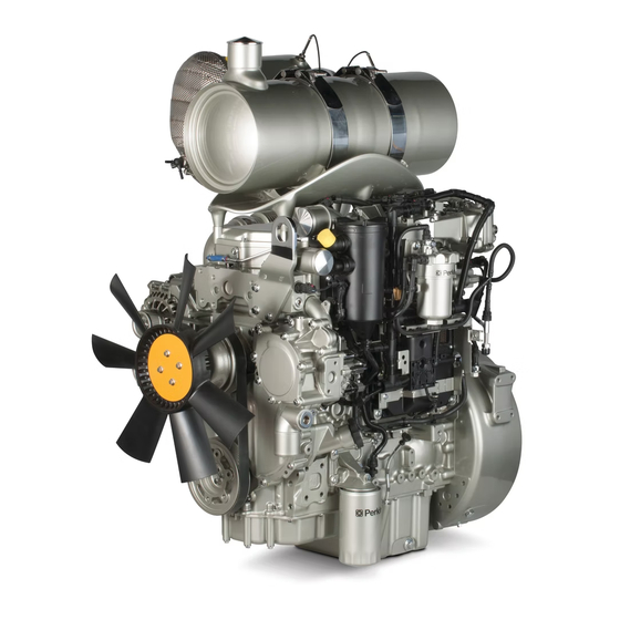
The following model views show typical features of the engine and the aftertreatment system. Due to individual applications, your engine, and your aftertreatment may appear different from the illustrations. 1204EA-E44TA Turbocharged Engine Illustration 16 g06763005 Typical example (1) Front lifting eye... - Page 22 M0135751 Product Information Section Model View Illustrations Illustration 17 g06763018 Typical example (4) NOx Reduction system (14) Refrigerant Compressor (19) Flywheel housing (10) Belt (15) Turbocharger (20) Exhaust Back Pressure Regulator (11) Rear lifting eye (16) Starter motor (EBPR) (12) Oil level gauge (dipstick) (17) Oil drain valve (13) Alternator (18) Flywheel...
- Page 23 M0135751 Product Information Section Model View Illustrations Illustration 18 g06763020 Typical example (21) Exhaust Back Pressure Regulator (22) Oil filler (24) Tensioner (EBPR) (23) Crankcase breather (25) Idler pulley Aftertreatment Systems For a general description of the aftertreatment refer to this Operation and Maintenance Manual, “Product Description”...
- Page 24 M0135751 Product Information Section Model View Illustrations Clean Emissions Module (CEM) - combined DPF and DOC, Illustration 19 g06763089 Typical example (1) Flexible exhaust pipe (3) DOC and DPF combined aftertreatment (4) Aftertreatment mounting bracket (2) Inlet for Exhaust gas system (5) Outlet for Exhaust gas...
- Page 25 M0135751 Product Information Section Model View Illustrations Off Engine Components Illustration 20 g06763426 Typical example (1) Temperature sensor (3) Fuel Filters (5) Flexible exhaust connection pipe (2) Soot sensor module (4) Inlet Air Temperature Sensor (6) Clean Emissions Module (CEM) Emissions-Related Components for China Non-Road IV The following model views show approximate...
- Page 26 M0135751 Product Information Section Model View Illustrations Illustration 22 g07116060 Typical example (B) Position of the DOC and DPF marking Illustration 25 g07116056 Typical example (E) Position of the ECM marking Illustration 23 g07168650 Typical example (C) Position of the turbocharger marking Illustration 26 g07168783 Typical example...
- Page 27 Stroke 127 mm (4.99 inch) Product Description Power Single turbocharger charge cooled 110 kW (147 hp) The 1204EA-E44TA is a single turbocharged engine. Aspiration Single Turbocharged charge cooled • Combined Diesel Oxidation Catalyst (DOC) and Compression Ratio 16.5:1 Diesel Particulate Filter (DPF) Displacement 4.4 L (268.504 cubic inch)
- Page 28 The aftertreatment system is approved for use by Perkins. To be emission-compliant, only the • Injection timing control approved Perkins aftertreatment system or approved components must be used on a Perkins engine. • System diagnostics Clean Emission Module (CEM) • Low temperature regeneration...
- Page 29 Aftermarket Products and Perkins Engines Perkins does not warrant the quality or performance of non-Perkins fluids and filters. When auxiliary devices, accessories, or consumables (filters, additives, catalysts) which are made by other manufacturers are used on Perkins products, the Perkins warranty is not affected simply because of such use.
-
Page 30: Product Identification Information
Plate Locations and Film Locations Illustration 31 g01094203 Engine Aftertreatment system Illustration 30 g06762035 Location of serial number plate Perkins engines are identified by an engine serial number. An example of an engine number is Illustration 32 g06762026 ST*****U000001W. Typical example • ST... - Page 31 Engine aftertreatment system identification plate Record all the information on the serial plate for your aftertreatment system. The information will be required by your Perkins distributors. i05673571 Emissions Certification Film The label for the emission is installed on the front gear cover.
- Page 32 M0135751 Product Information Section Reference Information Lubrication Oil Filter Element Auxiliary Oil Filter Element Total Lubrication System Capacity Total Cooling System Capacity Air Cleaner Element Drive Belt Aftertreatment Systems Clean Emission Module Part Number Clean Emission Module Serial Number...
-
Page 33: Operation Section
There are several different designs of lifting eyes. The following sections give examples of lifting eyes on the engine, engine, and aftertreatment and factory installed radiator. Consult your Perkins distributor for information regarding fixtures for proper engine lifting. Illustration 36 g06761744... - Page 34 The engine must be stored in a water proof building. The building must be kept at a constant temperature. Engines that are filled with Perkins ELC will have coolant protection to an ambient temperature of −36° C (−32.8° F). The engine must not be subjected to extreme variations in temperature and humidity.
- Page 35 Operation and Maintenance Manual, “Fluid recommendations”. 4. Remove the drive belt from the engine. Sealed Coolant System Ensure that the cooling system is filled with Perkins ELC, or an antifreeze that meets “ASTM D6210” specification. Open Cooling System Ensure that all cooling drain plugs have been opened.
-
Page 36: Features And Controls
M0135751 Operation Section Features and Controls Features and Controls NRS temperature – The pre-NRS valve and post- NRS valve temperature is monitored by the ECM. Intake manifold pressure – The intake manifold i08745820 pressure sensor checks the rated pressure in the Alarms and Shutoffs engine manifold. - Page 37 Determine and correct the cause of any significant procedures: change in the readings. Consult your Perkins 1. Reduce the load and the engine rpm. distributor for assistance. 2. Determine if the engine must be shut down Some engine applications are equipped with Indicator Lamps.
- Page 38 M0135751 Operation Section Monitoring System Engine - Electrical Preheat – This • Event codes indicator comes “ “ ON” ” to show that the • Coolant temperature glow plug preheat is active. The engine should be set to “ “ RUN” ” only after indicator lamp •...
- Page 39 1. One or more of the shutdown values for diagnostic code. the engine protection strategy has been exceeded. Contact your Perkins distributor. 2. A serious active diagnostic code has been detected. If installed, the audible warning will sound. After a short time period, the engine may shut down.
- Page 40 M0135751 Operation Section Sensors and Electrical Components An overspeed is detected by the speed/timing sensors. The default setting for an overspeed is 3000 rpm. The ECM will cut the power to the electronic unit injectors, until the rpm drops below 200 rpm of the overspeed setting.
- Page 41 M0135751 Operation Section Sensors and Electrical Components (5) Temperature Sensor for the NOx (7) Crankshaft Speed/Timing sensor (10) Suction Control Valve Reduction System (NRS) (8) Engine Oil Pressure Sensor (6) Electronic Control Module (ECM) (9) Fuel Temperature Sensor Illustration 39 g06777377 Typical example of close up views of sensor locations on the left side of the engine (1) Fuel pressure sensor (Fuel Rail Pressure...
- Page 42 M0135751 Operation Section Sensors and Electrical Components Illustration 40 g06777399 Typical example (12) NRS temperature sensor (13) NRS valve including a position sensor (14) NRS differential pressure sensor...
- Page 43 M0135751 Operation Section Sensors and Electrical Components Illustration 41 g06777695 Typical example of the sensor locations on the right side of the engine (15) Exhaust Back Pressure Regulator (16) Coolant temperature sensor (18) Camshaft speed/timing sensor (EBPR) (17) Refrigerant compressor (if equipped)
- Page 44 M0135751 Operation Section Sensors and Electrical Components Sensor Locations for the Clean Emissions Module (CEM) Illustration 42 g06731627 Typical example of the sensors and components on the Clean Emissions Module (CEM) (1) Soot sensor antenna (3) Diesel Oxidation Catalyst (DOC) inlet (5) Soot load sensor module (2) Diesel Oxidation Catalyst (DOC) inlet temperature sensor...
-
Page 45: Engine Diagnostics
A flashing YELLOW lamp indicates a 3-digit code for the engine. The sequence of flashes represents the system diagnostic message. Count the first Perkins Electronic Engines have the capability to perform a self-diagnostics test. When the system sequence of flashes in order to determine the first digit of the flash code. - Page 46 M0135751 Operation Section Engine Operation with Intermittent Diagnostic Codes System Configuration Parameters Operation of the engine and performance of the engine can be limited as a result of the active diagnostic code that is generated. Acceleration rates System configuration parameters affect the may be significantly slower.
- Page 47 M0135751 Operation Section Configuration Parameters (Table 3, contd) Factory Installed Aftertreatment #1 Identification Number DPF #1 Soot Loading Sensing System Configuration Code Limp Home Engine Speed Ramp Rate System Operating Voltage Configuration Rating Number CAN Communication Protocol Write Security Engine Emissions Operator Inducement Progress Configuration Engine Emissions Operator Inducement Regulation Configuration Customer Specified Parameters Customer specified parameters allow the engine to...
- Page 48 M0135751 Operation Section Configuration Parameters (Table 4, contd) Throttle Lock Feature Installation Status PTO Mode Throttle Lock Engine Set Speed #1 Throttle Lock Engine Set Speed #2 Throttle Lock Increment Speed Ramp Rate Throttle Lock Decrement Speed Ramp Rate Throttle Lock Engine Set Speed Increment Throttle Lock Engine Set Speed Decrement Monitoring Mode Shutdowns Monitoring Mode Derates...
- Page 49 M0135751 Operation Section Configuration Parameters (Table 4, contd) Engine Cooling Fan Minimum Air Flow Transmission Oil Temperature Engine Cooling Fan Control Hydraulic Oil Temperature Input Enable Status Engine Cooling Fan Maximum Air Flow Hydraulic Oil Temperature Engine Cooling Fan Minimum Air Flow Hydraulic Oil Temperature Engine Cooling Fan Control Auxiliary #1 Temperature Input Enable Status Engine Cooling Fan Maximum Air Flow Auxiliary #1 Temperature Engine Cooling Fan Minimum Air Flow Auxiliary #1 Temperature...
-
Page 50: Engine Starting
M0135751 Operation Section Engine Starting Engine Starting i07677844 Cold Weather Starting i03648917 Before Starting Engine Do not use aerosol types of starting aids such as Perform the required daily maintenance and other ether. Such use could result in an explosion and periodic maintenance before the engine is started. - Page 51 M0135751 Operation Section Starting the Engine 5. Repeat step 2 through step 4 if the engine fails to 3. When the warning light for the glow plugs is start. extinguished, turn the keyswitch to the START position to engage the electric starting motor and Note: After starting, the engine may be held at low crank the engine.
- Page 52 M0135751 Operation Section After Starting Engine Note: The engine ECM must be powered before the starting motor is operated or damage can occur. Improper jump start cable connections can cause 4. Start the engine in the normal operating an explosion resulting in personal injury. procedure.
- Page 53 M0135751 Operation Section After Starting Engine Note: Gauge readings should be observed and the data should be recorded frequently while the engine is operating. Comparing the data over time will help to determine normal readings for each gauge. Comparing data over time will also help detect abnormal operating developments.
-
Page 54: Engine Operation
M0135751 Operation Section Engine Operation Engine Operation Carbon Dioxide (CO ) Emissions Emissions regulations require that the value of the emissions be reported to the end user. For this i08748815 engine, 684.7 g/kWh was determined to be the CO Engine Operation value during the EU type approval process. - Page 55 Any warning should be investigated immediately. • Safe Harbor Mode (China NR4) Safe Harbor Contact your Perkins distributor if further assistance Mode is a 30 minute engine run time period. Once is required. in level 2 severe inducement, the operator can perform a key cycle and the engine will enter Safe The system is equipped with a safe harbor mode.
- Page 56 M0135751 Operation Section Engine Operation NOTICE It is essential to take prompt action to rectify any in- correct operation, use, or maintenance of the emis- sions NOx reduction system, particulate control system in accordance with the rectification measures indicated by the warnings listed on the following pages.
- Page 57 Contact your Perkins distributor at level 1 warning, do not let the fault develop. The emission malfunction lamp will be on solid or flashing depending on customer display configuration in the application. Additional escalated annunciation used by customer to indicate inducement level if the emission lamp is configured to on solid at level 2 (mild) and level 2 (Severe).
- Page 58 M0135751 Operation Section Fuel Conservation Practices Fuel expands when it is warmed up. The fuel may overflow from the fuel tank. Inspect fuel lines for leaks. Repair the fuel lines, as needed. • Be aware of the properties of different fuels. Use only the recommended fuels.
-
Page 59: Cold Weather Operation
Perkins Diesel Engines can operate effectively in cold weather. During cold weather, the starting and • Install the correct specification of engine lubricant the operation of the diesel engine depends on the before the beginning of cold weather. - Page 60 240 V ac. The output can be between 600W and deposit on the valve stems will be kept at a minimum. 750W. Consult your Perkins dealer or your Perkins The free operation of the valves and the valve distributor for more information.
- Page 61 M0135751 Operation Section Radiator Restrictions The Water Temperature Regulator and Consult with your Perkins dealer or your Perkins distributor for the recommended breather Insulated Heater Lines components for operation from −25° to -40°C (−13° to -72.°F). The engine is equipped with a water temperature regulator.
- Page 62 M0135751 Operation Section Fuel Related Components in Cold Weather Following properties are used to define fuels low Fuel tanks should contain some provision for draining temperature capability: water and sediment from the bottom of the tanks. Some fuel tanks use supply pipes that allow water •...
-
Page 63: Engine Stopping
M0135751 Operation Section Engine Stopping Engine Stopping i05784249 After Stopping Engine i06832774 Stopping the Engine Note: Before you check the engine oil, do not operate the engine for at least 10 minutes. This period will allow the engine oil to return to the oil pan. NOTICE Stopping the engine immediately after it has been working under load, can result in overheating and ac-... - Page 64 M0135751 Operation Section After Stopping Engine Pressurized System: Hot coolant can cause seri- ous burns. To open the cooling system filler cap, stop the engine and wait until the cooling system components are cool. Loosen the cooling system pressure cap slowly in order to relieve the pressure.
-
Page 65: Maintenance Section
M0135751 Maintenance Section Refill Capacities Maintenance Section Refill Capacities i08748818 Refill Capacities Lubrication System The refill capacities for the engine crankcase reflect the approximate capacity of the crankcase or sump plus standard oil filters. Auxiliary oil filter systems will require additional oil. Refer to the Original Equipment Manufacture (OEM) specifications for the capacity of the auxiliary oil filter. - Page 66 “EMA Recommended Guideline on Diesel Engine is left behind as the soot is burnt. This matter will Oil”. In addition to Perkins definitions, there are other eventually block the filter, causing loss of definitions that will be of assistance in purchasing performance and increased fuel consumption.
- Page 67 Note: API FA-4 oil is designed for use in selected on-highway applications and is NOT designed to support off-road applications, including Perkins Engines. DO NOT use API FA-4 oil for Perkins engines. These engine oils are not approved by Perkins and these engine oils must not be used: CC, CD, CD-2, CF-4, CG-4, CH-4, and CI-4.
- Page 68 Water, additives, and glycol. properties of the used oil sample. This analysis allows technicians to determine the amount of Refer to Perkins Diesel Engines Fluids deterioration of the oil during use. This analysis Recommendations, M0113102 for additional also allows technicians to verify the performance information that relates to coolant.
- Page 69 Until such standard/ • Plugging of radiators, coolers, and small passages specifications are published and evaluated by Perkins, use of PDO, glycerine, or other alternative Glycol coolants are not recommended in Perkins diesel engines.
- Page 70 Do not use a commercial coolant/antifreeze that only contains organic corrosion inhibitors and antifoam meets the ASTM D3306 specification. This type of agents with low amounts of nitrite. Perkins ELC has coolant/antifreeze is made for light automotive been formulated with the correct amount of these applications.
- Page 71 6. Fill the cooling system with the Perkins Premixed Clean water is the only cleaning agent that is ELC. Operate the engine. Ensure that all coolant required when ELC is drained from the cooling valves open then stop the engine.
- Page 72 Equation For Adding The SCA To The Heavy-Duty Coolant At regulations. Flush the system with a 5 to 10 The Initial Fill percent solution of Perkins ELC. Fill the system V × 0.07 = X with the Perkins ELC. V is the total volume of the cooling system.
- Page 73 • Fill the system with new coolant. Diesel Fuel Requirements i09605800 Fluid Recommendations Perkins is not in a position to continuously evaluate and monitor all worldwide distillate diesel fuel (General Fuel Information) specifications that are published by governments and technological societies.
- Page 74 M0135751 Maintenance Section General Fuel Information NOTICE The footnotes are key part of the "Perkins Specifica- tion for Distillate Diesel Fuel" Table. Read ALL of the footnotes. Table 17 "Perkins Specification for Distillate Diesel Fuel" Property UNITS Requirements “ASTM”Test “ISO/Other”Test...
- Page 75 Environmental Protection Agency of the United NOTICE States. In Europe, sulfur free diesel fuels with sulphur Operating with fuels that do not meet the Perkins rec- content less than 0.0010 percent (10 PPM) (mg/kg)) ommendations can cause the following effects: Start-...
- Page 76 10 PPM sulfur level” “GB 19147-2016” “Chinese diesel fuel” All the fuels must comply with the specification in the table for the Perkins Specification Distillate Diesel Fuel. Diesel Fuel Characteristics Cetane number affect engine cold start ability, exhaust emissions, combustion noise, and altitude performance.
- Page 77 The fluids lubricity describes the ability of the fluid to reduce the friction between surfaces that are Perkins recommends kinematic viscosities of 1.4 and under load. This ability reduces the damage that is 4.5 mm2/sec that is delivered to the fuel injection caused by friction.
- Page 78 Protection Agency (EPA) and European Certification emissions control strategies utilized in many of the fuels. Perkins does not certify engines on any other industrial latest engine designs may lead to a fuel. The user of the engine has the responsibility of...
- Page 79 EN 15751. If the test shows that the fuel has specification “CENTS 15940”. The fuel should also degraded, fuel tank must be drained and engine meet requirements described in table 17 , Perkins flashed by running with the fresh high-quality diesel Specification for Distillate Diesel Fuel, EN590, or fuel.
- Page 80 If biodiesel or biodiesel blends of fuel are to be used, lubricity section of this “Operation and Maintenance Perkins require the use of Perkins fuel cleaner. The Manual” Fluid Recommendations use of the fuel is to remove deposits within the fuel system that is created with the use of biodiesel.
- Page 81 500 ppm water or less. • Perkins recommends the use of bulk fuel filter / coalescer units which clean the fuel of both particulate contamination and water in a single pass.
-
Page 82: Maintenance Recommendations
Consult the OEM of the equip- To relieve the pressure from the coolant system, turn ment or your Perkins dealer regarding welding on a chassis frame or rail. off the engine. Allow the cooling system pressure cap to cool. - Page 83 M0135751 Maintenance Section Welding on Engines with Electronic Controls 1. Stop the engine. Turn the switched power to the OFF position. 2. Ensure that the fuel supply to the engine is turned off. 3. Disconnect the negative battery cable from the battery.
- Page 84 • The temperature of the fluid in the engine • Frequent hot shutdowns Refer to the standards for the engine or consult your Perkins distributor to determine if the engine is • Operating at excessive loads operating within the defined parameters.
-
Page 85: Maintenance Interval Schedule
M0135751 Maintenance Section Maintenance Interval Schedule “ Radiator - Clean“ ......111 i08746648 Maintenance Interval Schedule Every 1000 Service Hours “... -
Page 86: Battery - Replace
Aftercooler Core - Clean/Test Alternator - Inspect (Air-To-Air Aftercooler) Perkins recommends a scheduled inspection of the alternator. Inspect the alternator for loose The air-to-air aftercooler is OEM installed in many connections and correct battery charging. Check the applications. Please refer to the OEM specifications ammeter (if equipped) during engine operation in for information that is related to the aftercooler. -
Page 87: Battery Or Battery Cable - Disconnect
M0135751 Maintenance Section Battery Electrolyte Level - Check The battery cables or the batteries should not be All lead-acid batteries contain sulfuric acid which can burn the skin and clothing. Always wear a removed with the battery cover in place. The bat- face shield and protective clothing when working tery cover should be removed before any servic- on or near batteries. -
Page 88: Belt - Inspect
M0135751 Maintenance Section Belt - Inspect 3. Remove the positive connection. • Inspect the belt for cracks, splits, glazing, grease, displacement of the cord and evidence of fluid 4. Clean all disconnected connection and battery contamination. terminals. The belt must be replaced if the following conditions 5. -
Page 89: Clean Emissions Module Support - Inspect
M0135751 Maintenance Section Clean Emissions Module Support - Inspect Ensure that the belt tensioner (2) is securely NOTICE installed. Visually inspect the belt tensioner for When any servicing or repair of the engine cooling damage. Check that the pulley on the tensioner system is performed, the procedure must be per- rotates freely and that the bearing is not loose. - Page 90 Coolant (Commercial Heavy-Duty) - Change 1. Flush the cooling system with clean water and a suitable cleaning agent to remove any debris. Refer to your Perkins dealer or distributor for suitable cleaning agents. 2. Install connection hose. Clean the drain plugs.
-
Page 91: Coolant (Elc) - Change
M0135751 Maintenance Section Coolant (ELC) - Change Drain 2. Start and run the engine at low idle. Increase the engine rpm to high idle. Operate the engine to open the engine thermostat. This operation will allow any air in the system to be purged. Decrease the engine speed to low idle. -
Page 92: Coolant Level - Check
Decrease the engine speed to low idle. Stop the For information regarding the disposal and the engine. recycling of used coolant, consult your Perkins dealer 3. Maintain the coolant level at the maximum mark or Perkins distributor. that is correct for your application. - Page 93 M0135751 Maintenance Section Cooling System Supplemental Coolant Additive (SCA) - Test/Add Use a Coolant Conditioner Test Kit to check the concentration of the SCA. Add the SCA, If Necessary NOTICE Do not exceed the recommended amount of supple- mental coolant additive concentration. Excessive supplemental coolant additive concentration can form deposits on the higher temperature surfaces of the cooling system, reducing the engine's heat transfer...
-
Page 94: Engine - Clean
Note: The air filter system may not have been hazard. Keep the engine clean. Remove debris and provided by Perkins. The procedure that follows is for fluid spills whenever a significant quantity accumu- a typical air filter system. Refer to the OEM lates on the engine. -
Page 95: Engine Air Cleaner Service Indicator - Inspect
M0135751 Maintenance Section Engine Air Cleaner Service Indicator - Inspect • Check the pre-cleaner (if equipped) and the dust 5. Install the end cap (1) to the main body (2). Check bowl daily for accumulation of dirt and debris. and if necessary, reset the service indicator (4). Remove any dirt and debris, as needed. -
Page 96: Engine Air Precleaner - Check/Clean
Operation and Maintenance Manual, “Product wing nut (1). Description”. Within that section, refer to the title “Aftermarket Products and Perkins Engines”. Note: When the engine is operated in dusty conditions, more frequent cleaning is required. Do not tap or strike the air cleaner element. - Page 97 M0135751 Maintenance Section Engine Crankcase Breather Element (Emission Related Component) - Replace Illustration 57 g06623961 Illustration 58 g01884135 Typical example (B) Alignment position Note: The cut away from section (5) in the cap allows 1. Ensure that dirt cannot enter the breather access to the seal.
-
Page 98: Engine Oil Level - Check
Any engine mount that shows deterioration should be replaced. Refer to the OEM information for the recommended torques. When the engine mounts are supplied by Perkins the maintenance procedure will be supplied in the Disassembly and Assembly manual for your engine. -
Page 99: Engine Oil Sample - Obtain
Do not allow hot oil or hot components to valve is positioned on the cylinder block. contact the skin. Perkins recommends using a sampling valve in order to obtain oil samples. The quality and the consistency of the samples are better when a sampling valve is NOTICE used. - Page 100 Engine Oil sample - Obtain for more information. cations. Use of an oil filter that is not recommended by Perkins could result in severe damage to the en- If the engine is operated infrequently less than 500 gine bearings, crankshaft, as a result of the larger...
- Page 101 M0135751 Maintenance Section Engine Oil and Filter - Change Illustration 63 g02131364 Illustration 64 g02132333 Typical example Typical example 2. Clean sealing surface (1). 1. Place a suitable container below the oil filter assembly. Remove the drain plug (1) and allow the 3.
-
Page 102: Fan Clearance - Check
M0135751 Maintenance Section Fan Clearance - Check 6. Install the new oil filter. Spin on the oil filter (4) until 4. Remove the engine oil level gauge to check the oil the O ring contacts the sealing surface (2). Then level. - Page 103 M0135751 Maintenance Section Fan Clearance - Check Illustration 66 g03609316 Typical example • A is the fan tip clearance 7. Fan tip clearance at position (2) and (3) must be 14 ± 2 mm (0.55 ± 0.079 inch). 1. Set the fan tip clearance at position (1) to 16 mm (0.63 inch).
-
Page 104: Fuel System - Prime
M0135751 Maintenance Section Fuel System - Prime Illustration 67 g03609316 • A is the fan tip clearance Ensure that all adjustments and repairs are performed by authorized personnel that have had the 1. Set the fan tip clearance at position (1) to correct training. -
Page 105: Fuel System Primary Filter/Water Separator
5 minutes. Ensure that stalled every 250 service hours. For more information the fuel system is free from leaks. consult your Perkins distributor. Note: Operating the engine for this period will help ensure that the fuel system is free of air.DO NOT... - Page 106 M0135751 Maintenance Section Fuel System Primary Filter (Water Separator) Element - Replace Install the New Filter Element 3. Install a suitable tube onto drain (2). Open the drain valve (1). Rotate the drain valve fully counterclockwise. Two full turns are required. 4.
-
Page 107: Drain
M0135751 Maintenance Section Fuel System Primary Filter/Water Separator - Drain 6. The secondary filter element (if equipped) must be replaced at the same time as the primary filter element. Refer to the Operation and Maintenance Manual, “Fuel System Secondary Filter - Replace”. i07385529 Fuel System Primary Filter/ Water Separator - Drain... - Page 108 If the engine is operated at alti- tudes greater than 3000m, new fuel filters must be in- stalled every 250 service hours. For more information consult your Perkins distributor. Remove the Element 1. Turn the fuel supply valve (if equipped) to the OFF position before performing this maintenance.
-
Page 109: Fuel Tank Water And Sediment - Drain
M0135751 Maintenance Section Fuel Tank Water and Sediment - Drain Install the Element 6. Prime the fuel system. Refer to the Operation and Maintenance Manual, “Fuel System - Prime” for more information. i02348492 Fuel Tank Water and Sediment - Drain NOTICE Care must be taken to ensure that fluids are con- tained during performance of inspection, mainte-... -
Page 110: Hoses And Clamps - Inspect/Replace
M0135751 Maintenance Section Hoses and Clamps - Inspect/Replace Some fuel tanks use supply pipes that allow water Check for the following conditions: and sediment to settle below the end of the fuel supply pipe. Some fuel tanks use supply lines that •... -
Page 111: Radiator - Clean
Direct the air in the opposite direction of the air flow. Hold the nozzle approximately 6 mm Perkins recommends a scheduled inspection of the (0.25 inch) away from the fins. Slowly move the air starting motor. If the starting motor fails, the engine nozzle in a direction that is parallel with the tubes. -
Page 112: Turbocharger - Inspect
Refer to the Systems Operation, Testing and Adjusting Manual, “Electric Starting System - Test” for more information on the checking procedure and for specifications consult your Perkins dealer or your Perkins distributor for assistance. i08746477 Turbocharger - Inspect Hot engine components can cause injury from burns. -
Page 113: Walk-Around Inspection
Remove the water pump. Refer to Disassembly and Assembly, “Water Pump - Remove and Install”. For more information, consult your Perkins dealer or your Perkins distributor. Illustration 77 g02137093 • Inspect the lubrication system for leaks at the front... -
Page 114: Water Pump - Inspect
M0135751 Maintenance Section Water Pump - Inspect Belts for multiple groove pulleys must be replaced as • Check the condition of the gauges. Replace any matched sets. If only one belt is replaced, the belt will gauges that are cracked. Replace any gauge that carry more load than the belts that are not replaced. - Page 115 M0135751 Maintenance Section Water Pump - Inspect Note: If engine coolant enters the engine lubricating system the lubricating oil and the engine oil filter must be replaced. This will remove any contamination that is caused by the coolant and this will prevent any irregular oil samples.
-
Page 116: Warranty Section
1 through Tier 4 marine auxiliary engines < 37 kW, Warranty supplement - Emission warranty parts but excluding locomotive and other marine available at the Perkins engines website. Consult engines) operated and serviced in the state of your authorized Perkins distributor to determine if... -
Page 117: Reference Information Section
Maintenance records are a key element of a maintenance program that is correctly managed. Accurate maintenance records can help your Perkins dealer to fine-tune the recommended maintenance intervals in order to meet the specific operating situation. This should result in a lower engine operating cost. - Page 118 M0135751 Reference Information Section Maintenance Log i05204675 Maintenance Log Table 19 Engine Model Customer Identifier Arrangement Number Serial Number Service Quantity Of Service Item Date Authorization Hours Fuel...
- Page 119 Why buy an Extended Service Contract? 1. No surprises - total protection from unexpected repair cost (parts, labor, and travel). 2. Enjoy longer lasting product support from Perkins global network. 3. Genuine Perkins parts ensure continued engine performance. 4. Highly trained technicians carry out all repairs.
-
Page 120: Index
M0135751 Index Section Index Fill ..............92 Flush ............92 After Starting Engine ........52 Coolant Level - Check ........92 After Stopping Engine ........63 Cooling System Supplemental Coolant Aftercooler Core - Clean/Test (Air-To-Air Additive (SCA) - Test/Add......93 Aftercooler) ............ - Page 121 M0135751 Index Section Engine Operation with Active Diagnostic Fuel System Secondary Filter - Replace ..107 Codes ............45 Install the Element ........109 Engine Operation with Intermittent Remove the Element ......... 108 Diagnostic Codes .......... 46 Fuel Tank Water and Sediment - Drain ..109 Engine Starting..........
- Page 122 Maintenance Records ........117 Cooling System..........65 Maintenance Section........65 Lubrication System ........65 Model View Illustrations ........21 1204EA-E44TA Turbocharged Engine ..21 Aftertreatment Systems ....... 23 Safety Messages..........6 Emissions-Related Components for China Ether Warning ..........7 Non-Road IV ..........25 Hand (High Pressure) (2) ......
- Page 123 M0135751 Index Section Water Pump - Inspect........114 Welding on Engines with Electronic Controls ............82...
- Page 125 Product and Dealer Information Note: For product identification plate locations, see the section “Product Identification Information” in the Operation and Maintenance Manual. Delivery Date: Product Information Model: Product Identification Number: Engine Serial Number: Transmission Serial Number: Generator Serial Number: Attachment Serial Numbers: Attachment Information: Customer Equipment Number: Dealer Equipment Number:...
- Page 126 M0135751 ©2022 Perkins Engines Company Limited All Rights Reserved August 2022...