Kenwood KCA-BT100 Service Manual
Bluetooth hands free box
Hide thumbs
Also See for KCA-BT100:
- Instruction manual (144 pages) ,
- Instruction manual (12 pages) ,
- Instruction manual (22 pages)
Table of Contents
Advertisement
Quick Links
Download this manual
See also:
Instruction Manual
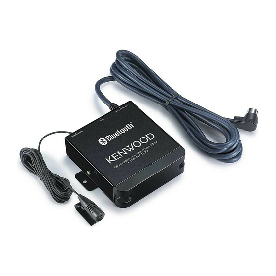
Bluetooth HANDS FREE BOX
KCA-BT100
SERVICE MANUAL
About removing the 2 hexagonal head screws :
"TORX T8 Screwdriver" is necessary.
Magic tape
(H30-0600-04)
Screw set
(N99-1789-05)
© 2006-11 PRINTED IN JAPAN
B53-0472-00 ( N ) 955
Cord with DIN connector
(E30-6645-05)
Microphone (3m)
(W01-1676-05)
This product uses Lead Free solder.
Advertisement
Table of Contents

Related Manuals for Kenwood KCA-BT100


Summary of Contents for Kenwood KCA-BT100
- Page 1 Bluetooth HANDS FREE BOX KCA-BT100 SERVICE MANUAL © 2006-11 PRINTED IN JAPAN B53-0472-00 ( N ) 955 Cord with DIN connector (E30-6645-05) About removing the 2 hexagonal head screws : “TORX T8 Screwdriver” is necessary. Magic tape Microphone (3m) Screw set...
-
Page 2: Block Diagram
KCA-BT100 BLOCK DIAGRAM ROM CORRECTION (NOT USED) (LX-BUS I/F) E2PROM FLASH SW5V Lch2 AGND2 BU5V CLK1 Rch2 MAIN DATAH1 u-COM MUTE2 DATAC1 REQH1 CLK2 REQC1 PON2 DATAH2 DATAC2 CHCON1 REQH2 RSTN REQC2 MUTEN CHCON2 BEEP RESET2 IC13 BU5V MIC INPUT 3.3V... -
Page 3: Microcomputer's Terminal Description
KCA-BT100 COMPONENTS DESCRIPTION Ref. No. Application / Function Operation / Condition / Compatibility Changer CONT Vc=L: Head unit is used, Vc=H: Head unit is not used BU DET BU ON: Vc=L, BU OFF: Vc=H BU5V AVR Q16’s Vb=H: 5V ON... -
Page 4: Main Μ-Com: Ic3 On X32- (Processor Unit)
KCA-BT100 MICROCOMPUTER’S TERMINAL DESCRIPTION Pin No. Pin Name Application Processing / Operation / Description RESET Reset input L: Reset REQH0 Communication request input from head unit L: Communication request is found BUDET Detection input of momentary power down H: Detection of momentary power down... - Page 5 KCA-BT100 MICROCOMPUTER’S TERMINAL DESCRIPTION Pin No. Pin Name Application Processing / Operation / Description LX MUTE Mute request to master unit L: Mute ON, H: Mute OFF LX REQ S Communication request to master unit Pull-down (GND) ROM SCL E2PROM clock for ROM correction Pull-up (B.U.)
-
Page 6: Test Mode
KCA-BT100 TEST MODE How to enter the test mode Flash ROM check function Set the connected head unit to the test mode to enter the To check connection of the external flash ROM. test mode. • How to enter the test mode Set Lo level at pin 23 of the main µ-com (IC3) and then... -
Page 7: Replacing Parts
• After parts or Processor Unit (X32-) is replaced, connect Therefore, Bluetooth RF Module (A1) and Main µ-COM (IC3) Bluetooth compatible cell phone to KCA-BT100, and check cannot be replaced. Hands-free calls. When Bluetooth RF Module (A1) or Main µ-COM (IC3) has •... - Page 8 KCA-BT100 PC BOARD (COMPONENT SIDE VIEW) PROCESSOR UNIT X32-5852-70 (J76-0207-12) CP16 CP17 CP15 CP14 CP23 IC10 IC13 IC11 MICROPHONE DISPLAY 5L INTERFACE SELECT X32-5852-70 Ref. No. Address Ref. No. Address IC10 IC11 IC13 Refer to the schematic diagram for the values of resistors and capacitors.
- Page 9 KCA-BT100 PC BOARD (FOIL SIDE VIEW) PROCESSOR UNIT X32-5852-70 (J76-0207-12) SW3.3V S-BOOTE ROMWR RESET SW5V CNVSS B.U5V RFTEST TXDI BOOTE MCLK RXDO MTXD SRTS CTSO MRXD CP13 IC12 ESD-GND X32-5852-70 Ref. No. Address IC12 Refer to the schematic diagram for the values of resistors and capacitors.
- Page 10 KCA-BT100 PROCESSOR UNIT (X32-5852-70) 780058GC653A DISPLAY 30620FCP4W2GP SELECT S-80835CNNB-G TC74LVX08FT TC7WT126FU-F AK2301A TP15 MBM29F800TA70 5.0V BA33BC0WFP IC10 SI-8050JDNF CP12 IC11 TC4066BFT(N) IC12,13 NJM4580V-ZB Q1-3 DTC124EUA Q5,9,16 2SC4081 2SB1184 LX DATA S DTC144EUA LX DATA M UMG2N LX CLK CPH3105-E BYTE...
- Page 11 KCA-BT100 from 5L INTERFACE (CHANGER) AUDIO GND SW 4.7K CP18 CP19 47 10u16 10u16 10u16 CP20 47 10u16 MAIN u-COM 5.0V VCC2 TP33 CP21 47 ANALOG SW IC11 8.0V TP34 I/O1 O/I1 CONT1 R71 47 TP35 CP22 47 O/12 4.0V...
-
Page 12: Exploded View
KCA-BT100 EXPLODED VIEW M2.6x8 : N09-6431-05 : N89-2605-43 : N89-2605-48 About removing the screw “A” which is a hexagonal head screw : “TORX T8 Screwdriver” is necessary. (X32-) About replacing “10” : This is a part which is only for service. -
Page 13: Parts List
KCA-BT100 PARTS LIST New parts Parts without Parts No. are not supplied. Les articles non mentionnes dans le Parts No. ne sont pas fournis. Teile ohne Parts No. werden nicht geliefert. Desti- Desti- Ref. No. Parts No. Description Ref. No. - Page 14 KCA-BT100 PARTS LIST PROCESSOR UNIT (X32-5852-70) Desti- Desti- Ref. No. Parts No. Description Ref. No. Parts No. Description nation nation RK73GB2A472J CHIP R 4.7K J 1/10W UDZS9.1B ZENER DIODE RK73GB2A104J CHIP R 100K J 1/10W RB160L-40 DIODE RK73PB2H1R0J CHIP R...
- Page 15 KCA-BT100 PARTS LIST CAPACITORS 2 2 0 • Capacitor value CC45 Color* 010 = 1pF 0 = 22pF 1 = Type ... ceramic, electrolytic, etc. 4 = Voltage rating 100 = 10pF 2 = Shape ... round, square, etc. 5 = Value...
-
Page 16: Specifications
Operating voltage (11~16V allowable) ..............14.4V Current consumption ....................0.2A Dimension (W x H x D) ..............95 x 30 x 105 mm Weight ........................ 0.35kg KENWOOD follows a policy of continuous advancements in development. For this reason specifications may be changed without notice.