Table of Contents
Advertisement
®
Installation, Operation and Maintenance Manual
Please read and save these instructions for future reference. Read carefully before attempting to assemble, install,
operate or maintain the product described. Protect yourself and others by observing all safety information. Failure
to comply with instructions could result in personal injury and/or property damage!
General Safety Information
Only qualified personnel should install this unit.
Personnel should have a clear understanding of these
instructions and should be aware of general safety
precautions. Improper installation can result in electric
shock, possible injury due to coming in contact with
moving parts, as well as other potential hazards. Other
considerations may be required if high winds or seismic
activity are present. If more information is needed,
contact a licensed professional engineer before moving
forward.
1. Follow all local electrical and safety codes, as well
as the National Electrical Code (NEC), the National
Fire Protection Agency (NFPA), where applicable.
Follow the Canadian Electrical Code (CEC) in
Canada.
2. The rotation of the wheel is critical. It must be free
to rotate without striking or rubbing any stationary
objects.
3. Motor must be securely and adequately grounded.
4. Do not spin fan wheel faster than the maximum
cataloged fan rpm. Adjustments to fan speed
significantly affects motor load. If the fan RPM is
changed, the motor current should be checked to
make sure it is not exceeding the motor nameplate
amps.
5. Do not allow the power cable to kink or come in
contact with oil, grease, hot surfaces, or chemicals.
Replace cord immediately if damaged.
6. Verify that the power source is compatible with the
equipment.
7. Never open blower access doors while the fan is
running.
®
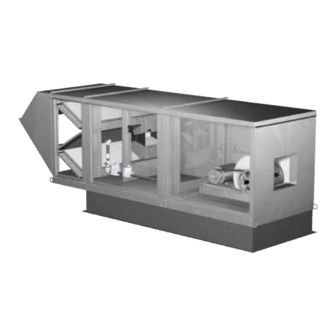
Direct Spark Ignition Make-Up Air
DANGER
Always disconnect power before working on or near a
unit. Lock and tag the disconnect switch or breaker to
prevent accidental power up.
CAUTION
When servicing the unit, motor may be hot enough
to cause pain or injury. Allow motor to cool before
servicing.
FOR YOUR SAFETY
If you smell gas:
1. Open windows.
2. Do not touch electrical switches.
3. Extinguish any open flame.
4. Immediately call your gas supplier.
FOR YOUR SAFETY
The use and storage of gasoline or other
flammable vapors and liquids in open
containers in the vicinity of this appliance is
hazardous.
WARNING
Improper installation, adjustment, alteration,
service or maintenance can cause
property damage, injury or death. Read the
installation, operating and maintenance
instructions thoroughly before installing or
servicing this equipment.
Direct Spark Ignition Make-Up Air
Document 470652
Model DG and DGX
1
Advertisement
Table of Contents

Related Manuals for Greenheck DG


Summary of Contents for Greenheck DG
- Page 1 Document 470652 Model DG and DGX Direct Spark Ignition Make-Up Air ® Installation, Operation and Maintenance Manual Please read and save these instructions for future reference. Read carefully before attempting to assemble, install, operate or maintain the product described. Protect yourself and others by observing all safety information. Failure...
- Page 2 If damaged, immediately contact your Greenheck Representative. The fan should be placed on a level surface to prevent Any physical damage to the unit after acceptance is not water from leaking into the unit.
-
Page 3: Table Of Contents
Table of Contents Installation of Indoor Unit 1. Install Hangers Installation Clearance to Combustibles/Service Clearances ..3 Install threaded hangers from ceiling supports. When Indoor Unit ....... . . 3 locating hangers, allow enough room to open access Unit Arrangement DB / HZ / UB . -
Page 4: Unit Arrangement Db / Hz / Ub
Installation of Arrg. DB / HZ / UB 3. Apply Sealant Apply an appropriate sealant around the perimeter of 1. Install Curb and/or Equipment/Leg Support(s) the curb and duct adapter(s) to isolate fan vibration and Position curb and/or equipment/leg support(s) on the prevent water penetration. -
Page 5: Roof Mounted Unit - Arrangement Dbc
Installation of Roof Mounted Unit NOTE Arrangement DBC The use of a duct adapter is recommended on a downblast (DBC) arrangement to align the ductwork 1. Install Curb/Equipment Support(s) with the supply unit. The duct adapter is only a guide Position curb/equipment support(s) on the roof and is not to be used as a support for the ductwork. -
Page 6: Optional Evaporative Cooler Module
Installation of Evaporative Cooling 7. Install Supply Unit Use a crane and a set of spreader bars hooked to Module (optional) the factory lifting lugs to lift and center the unit on the extension/equipment support(s). NOTE Use self-tapping sheet metal screws to fasten the unit Small evaporative coolers ship attached to the base to the extension/equipment support(s). -
Page 7: Electrical Wiring
Installation of Electrical Wiring 1. Determine the Size of the Main Power Lines The unit’s nameplate states the voltage and the unit’s MCA. The main power lines to the unit should be sized IMPORTANT accordingly. The nameplate is located on the outside of Before connecting power to the unit, read and the unit on the control panel side. -
Page 8: Direct Gas Piping
Installation of Direct Gas Piping 1. Determine the Supply Gas Requirements The unit’s direct gas nameplate states the requirements for the gas being supplied to the unit. The direct gas IMPORTANT nameplate is located on the outside of the unit on the All gas piping must be installed in accordance control center side. -
Page 9: Optional Evaporative Cooler Piping
Installation Evaporative Cooler 4. Pipe the Optional Vent Line If an optional vent line is located between the safety Piping (optional) shutoff valves, it must be piped to the outdoors. Evaporative Cooling with Recirculating Pump WARNING Supply Line Reference the National Fuel Gas Code for additional vent line requirements. - Page 10 Installation Evaporative Cooler 1. Install the Water Supply Line Supply line opening requirements vary by unit size Piping (optional) continued and arrangement and are field-supplied. Connect the water supply line to the float valve through the supply Evaporative Cooling with Auto Drain and Fill line opening in the evaporative cooling unit.
-
Page 11: Optional Water Wizard
1/2 inch 383086 8210G34 Line Open DGX-H32 (12.7 mm) the terminal strip in the unit’s control center. Drain (<9000 cfm) DG-H30 3/4 inch NOTE 383088 8210G9 Supply Closed (19.05 mm) DGX-H32 The Water Wizard™ start-up must be completed for (≥9000 cfm) -
Page 12: Optional Direct Expansion (Dx) Coil Piping
Installation of Direct Expansion (DX) NOTE Coil Piping (optional) If a hot gas bypass kit was provided by others, refer to the manufacturer’s instructions. IMPORTANT 3. Install Suction Line Guidelines for the installation of direct expansion Install suction line(s) from the compressor to the suction cooling coils have been provided to ensure proper connection(s) which are stubbed through the side of the performance and longevity of the coils. -
Page 13: Optional Chilled Water Coil Piping
Installation of Chilled Water Coil 7. Evacuate and Charge the Coil Use a vacuum pump to evacuate the coil and any Piping (optional) interconnecting piping that has been open to the atmosphere. Measure the vacuum in the piping using a IMPORTANT micron gauge located as far from the pump as possible. -
Page 14: Optional Building Pressure Control
Installation of Building Pressure Installation of Dirty Filter Switch Control (optional) (optional) To adjust the switch, the unit must be running with 1. Mount Pressure Tap all of the access doors in place, except for the Using the factory provided bracket, mount the pressure compartment where the switch is located (exhaust tap to the outside of intake compartment). -
Page 15: Blower
Start-Up - Blower 3. Check for Vibration Check for unusual noise, vibration or overheating of the Refer to the Start-Up Checklist in the Reference bearings. Reference the Troubleshooting section for section before proceeding further! corrective actions. Pre Start-Up Check IMPORTANT Rotate the fan wheel by hand and make sure no parts Excessive vibration may be experienced during are rubbing. - Page 16 Start-Up - Direct Gas IMPORTANT Proper air velocity over the burner is critical on direct IMPORTANT fired gas units. If the air velocity is not within the unit For proper unit function and safety, follow the start-up specifications, the unit will not operate efficiently, procedure in the exact order that it is presented.
- Page 17 4. Set the Low Fire Time Delay IMPORTANT Set the low fire time delay to 75% of its maximum setting. Setting the maximum firing rate during mild weather See below for the location of the time delay setting. conditions may cause the high limit to trip out during NOTE extreme conditions requiring manual resetting.
- Page 18 7. Set the Unit’s Operating Temperature Maxitrol SC25S - The SC25S is an analog signal converter that will change a 0-10 VDC or a 4-20 mA Set the operating temperature. The operating control signal provided by an owner-supplied Building temperature setting depends on which Maxitrol Management System into an output level capable of controller is used.
-
Page 19: Optional Evaporative Cooling Recirculating
Start-Up - Evaporative Cooling 7. Set the Optional Auto Drain and Fill This system will automatically drain the sump tank and Recirculating (optional) fill it with fresh water at the field-adjustable intervals, typically once every 24 hours. This flushes mineral 1. -
Page 20: Optional Water Wizard
Water Pressure Option setting. Size (inches) (in. wg) Use the Up and Down keys to adjust the Minimum DG-10 ⁄ Cooling Temperature as needed. Press the Enter key DG-20 to save the Minimum Cooling Temperature setting and DG-30 return to the Program Menu. -
Page 21: Optional Water Wizard
NOTE CAUTION The Freeze Temperature is preset to the factory The sump drain line must be clear and draining to a recommended 45ºF. Steps 9-11 should only safe location before using Flow Test Mode. be completed if the Freeze Temperature needs CAUTION adjustment. -
Page 22: Optional Vav Units
Check Operation - VAV Units Building Pressure Control BLOWER - a variable frequency drive is EXHAUST (optional) (OPTIONAL) SUPPL Y controlled according to input MAIN V AL VES HEA T from a pressure sensing device. NOTE Turn both knobs to the upper DIRTY FIL TERS Blower Start-Up, Steps 1-5 should be performed most pressure setting. -
Page 23: Optional Recirculating Units
Check Operation - Recirculating Building Pressure Control - a BLOWER modulating spring return actuator EXHAUST Units (optional) (OPTIONAL) SUPPL Y is used to control the return air MAIN V AL VES HEA T amounts. The return air damper NOTE modulates from fully open to fully DIRTY FIL TERS Blower Start-Up, steps 1-5 should be performed closed based on a signal from a... -
Page 24: Direct Gas
Operation - Electrical Electrical Sequence • Power passes to terminal TH on the Flame Safeguard (FSG) which begins it’s sequence 1. Exhaust Fan Contact (S1) Closed (optional) (see Direct Gas Burner Sequence) • Power passes to N.C. exhaust overload contact 4. -
Page 25: Troubleshooting
Troubleshooting Blower Does Not Operate Proper supply power at main disconnect Check Main Voltage (See Blower Start-Up Step #1) Main Disconnect (DS1) Off (Turn Main Disconnect DS1 On) Primary Fuses Blown (Replace Fuses) 24 VAC between terminals R and X? Main Transformer (TR1) Defective (Replace Transformer) 24 VAC between... -
Page 26: Motor Overamps
Troubleshooting Motor Overamps Air volume too high? Adjust drives or increase external static pressure as needed. (Reference Blower Start-Up – Step #5) Actual static pressure lower than design? Adjust drives to reduce blower RPM. (Reference Blower Start-Up – Step #5) Blower rotation correct? Reverse blower rotation. -
Page 27: Insufficient / Too Much Airflow
Troubleshooting Insufficient Airflow Damper(s) not fully opened? Adjust damper linkage(s), or replace faulty actuator(s). (Damper actuators may take a few minutes to open) System static losses too high? Reduce losses by improving ductwork. Blower speed too low? Adjust drives as needed. (Reference Blower Start-Up –... -
Page 28: Excessive Noise Or Vibration
Troubleshooting Excessive Noise or Vibration Belts worn or loose? Replace worn belts or tighten loose belts. (Reference V-Belt Drives in the Maintenance section) Sheaves aligned? Align sheaves. (Reference V-Belt Drives in the Maintenance section) Wheel(s) unbalanced? Clean and/or balance wheel(s). Bearings worn or need lubrication? Replace worn bearings or lubricate bearings as needed. -
Page 29: Direct Gas Heater Does Not Operate
Troubleshooting Heater Does Not Operate Does not attempt to light (No visible spark) 24 VAC between terminals W1 and X? Heat Switch (S4) Off (Turn Heat Switch (S4) On) Heat Switch Not Wired (Wire Heat Switch (S4)) 115 VAC between terminals 102 and 101? Primary Fuses Blown (Replace Fuses) - Page 30 Troubleshooting Heater Does Not Operate Attempts to light, but no flame (Visible spark) Is the low fire set properly (Direct Gas Start-Up Step #6) Adjust the low fire setting (Reference Direct Gas Start-Up Step #6) Check inlet gas pressure. (Direct Gas Start-Up Step #1) Gas pressure between the minimum and maximum shown on the direct gas label?
-
Page 31: Optional Evaporative Cooling
Troubleshooting Evaporative Cooler does not Operate (Recirculating pump) Supply fan must be on for cooler to operate 24 VAC between terminals Cool switch (S4) off Y1 and X (Turn cool switch (S4) on) Cool switch not wired (Wire cool switch (S4)) 24 VAC between terminal A2 on Cooling Relay (RC) and X Optional inlet air sensor (TS4) holding... -
Page 32: Optional Water Wizard
Troubleshooting Water Wizard™ — Improper Water Supply 4. Exit Program Mode After 15 seconds of idle time the controller will NOTE automatically exit Program Mode If the water supply is too low, the media will continuously appear dry. NOTE If the water supply is too high, the media will be saturated and excessive water will be draining from the sump tank. -
Page 33: Routine
Maintenance - Routine Snow Accumulation CAUTION Clear snow away from roof mounted units. Keep the Lock-out the gas and the electrical power to the snow clear of the intake and access doors. unit before performing any maintenance or service Wheels operations to this unit. - Page 34 Motors Evaporative Coolers Motor maintenance is generally limited to cleaning and The media should be periodically brushed lightly with lubrication (where applicable). a soft bristle brush in an up and down motion while flushing with water. This aids in reducing the amount of Cleaning should be limited to exterior surfaces only.
-
Page 35: Fall
Maintenance - Fall Winterizing Chilled Water Coils Start-Up During the winter, chilled water coils need to be Repeat the Blower Start-Up Step #5 and Direct Gas protected against freezing. Manufacturer recommends Start-Up Steps #1, #2 and #3. This will ensure that the protecting the coils by either blowing-out the coils or by gas and air are set properly before the heating season flushing the coils. -
Page 36: Gas Train Layout
Reference Typical Gas Train Layout with Direct Spark Ignition This is a typical gas train. The gas train in your unit may be different. Burner Differential Pressure Sensor (Airflow Switch) to Burner Modulating Combination Shut-Off Low Gas Pressure Valve Valve/Regulator Switch (optional) Burner Manual Shut-Off Valve... -
Page 37: Control Center Layout
Reference Control Center Layout 1. Supply Motor Starter — 24 volt magnetic contacts 18. Flame Safeguard/Spark Generator — monitors for starting supply motor. flame, shuts down unit when unsafe conditions are detected. 2. Supply Overload — provides electronic overload protection to supply motor. 19. -
Page 38: Start-Up Check List
Reference - Start-Up Checklist Start-Up Direct Gas Unit Model Number ________________________________ (e.g. DGX-120-H32) Refer to Direct Gas Start-Up section for further detail. o Check supply gas pressure Unit Serial Number _________________________________ (e.g. 10111000) _________ Maximum _________ Minimum Start-Up Date _____________________________________ _________ Actual Start-Up Personnel Name __________________________ o Set optional High Gas Pressure Switch... -
Page 39: Maintenance Log
Maintenance Log Date ___________________Time _____________ AM/PM Date ___________________Time _____________ AM/PM Notes: ___________________________________________ Notes: ___________________________________________ _________________________________________________ _________________________________________________ _________________________________________________ _________________________________________________ _________________________________________________ _________________________________________________ _________________________________________________ _________________________________________________ Date ___________________Time _____________ AM/PM Date ___________________Time _____________ AM/PM Notes: ___________________________________________ Notes: ___________________________________________ _________________________________________________ _________________________________________________ _________________________________________________ _________________________________________________ _________________________________________________ _________________________________________________ _________________________________________________ _________________________________________________ Date ___________________Time _____________ AM/PM... - Page 40 Our Commitment As a result of our commitment to continuous improvement, Greenheck reserves the right to change specifications without notice. Specific Greenheck product warranties are located on greenheck.com within the product area tabs and in the Library under Warranties. Greenheck’s Direct Gas-Fired Make-Up Air, Models DGK, DG...