Table of Contents
Advertisement
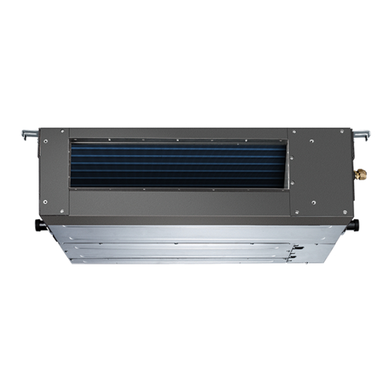
MIDDLE STATIC PRESSURE DUCT TYPE AIR CONDITIONER
Installation Manual
Middle Static Pressure Duct Type
MEU-18MPH2
MEU-24MPH2
MEU-36MPT2
MEU-48MPT2
IMPORTANT NOTE:
Read this manual carefully before
installing or operating your new air
conditioning unit. Make sure to save
this manual for future reference.
Advertisement
Table of Contents

Related Manuals for Midea MEU-18MPH2


Summary of Contents for Midea MEU-18MPH2
- Page 1 MIDDLE STATIC PRESSURE DUCT TYPE AIR CONDITIONER Installation Manual Middle Static Pressure Duct Type MEU-18MPH2 MEU-24MPH2 MEU-36MPT2 MEU-48MPT2 IMPORTANT NOTE: Read this manual carefully before installing or operating your new air conditioning unit. Make sure to save this manual for future reference.
-
Page 2: Table Of Contents
Table of Contents Installation Manual Accessories ............ 04 Safety Precautions ........05 Installation Overview ....... 06 Indoor Unit Installation ......07 a. Indoor Unit Parts ........07 b. Indoor Unit Installation Instructions ..08 Outdoor Unit Installation ......12 a. Outdoor Unit Installation Instructions ..12 b. - Page 3 Refrigerant Piping Connection .......17 A. Notes on Pipe Length and Elevation ....17 B. Refrigerant Piping Connection Instructions ... 1 8 Wiring ..........20 a. Outdoor Unit Wiring ....20 b. Indoor Unit Wiring ..... 21 c. Power Specifications ....23 Air Evacuation ..........25 a.
-
Page 4: Accessories
Accessories The air conditioning system comes with the following accessories. Use all of the installation parts and accessories to install the air conditioner. Improper installation may result in water leakage, electrical shock and fire, or equipment failure. NAME SHAPE QUANTITY Soundproof / insulation sheath Tubing &... -
Page 5: Safety Precautions
Safety Precautions Read Safety Precautions Before Installation Incorrect installation due to ignoring instructions can cause serious damage or injury. The seriousness of potential damage or injuries is classified as either a WARNING or CAUTION. Failure to observe a warning may result in death. The product must be installed by installers or contractors who are licenced HVAC professionals and in compliance The product must be installed by installers or with all local and state and provincial laws. -
Page 6: Installation Overview
Installation Overview INSTALLATION ORDER Install the indoor unit Install the outdoor unit Install the drainpipe (Page 7) (Page 13) (Page 15) Evacuate the refrigeration system Connect the wires Connect the refrigerant pipes (Page 25) (Page 20) (Page 17) Perform a test run (Page 27) ... -
Page 7: Indoor Unit Installation
Indoor Unit Installation Indoor Unit Parts Air inlet Electric control cabinet Air filter(on selected models) Drain hose Air outlet Refrigerant connecting pipe Fig. 4.1 Safety Precautions CAUTION WARNING • Securely install the indoor unit on a structure • Install the indoor and outdoor units, cables that can sustain its weight. -
Page 8: Indoor Unit Installation Instructions
Step 2: Hang indoor unit. 1. Please refer to the following diagrams to locate the four positioning screw bolt holes on the ceiling. Be sure to mark the paces where you will drill ceiling hook holes. Air outlet dimensions Air inlet dimensions Air filter Descending ventilation opening and mounted hook Air filter... - Page 9 3. Install hanging screw bolts. Wood Cut off the roof beam. Place the wood mounting across the roof beam, then install the hanging screw bolts.(See Fig.4.4) Strengthen the point at which the cut was made. Consolidate the roof beam. Wood mounting 4.
- Page 10 Step 3: Duct and accessories installation 1. Install the filter (optional) according to the size of the air inlet. 2. Install the canvas tie-in between the body and the duct. 3. The air inlet and air outlet duct should be far enough apart enough to a avoid air passage short-circuit.
- Page 11 Make sure this can be used in the field and provide the Step 4: Adjust the air inlet direction Step 5: Fresh air duct installation flange accessory. (from rear side to under-side). Dimension : Duct joint for fresh air 1. Take off the ventilation panel and flange. Air return flange MODLE 18-60...
-
Page 12: Outdoor Unit Installation
Outdoor Unit Installation √ The area must be free of combustible gases Outdoor Unit Installation Instructions and chemicals. √ The pipe length between the outdoor and Step 1: Select installation location. indoor unit may not exceed the maximum The outdoor unit should be installed in the allowable pipe length. - Page 13 Split Type Outdoor Unit Vertical Discharge Type Outdoor Unit (Refer to Fig 5.4, 5.5, 5.6, 5.10 and Table 5.1) (Refer to Fig 5.7, 5.8, 5.9 and Table 5.2) (Wall or obstacle) Air Outlet >120cm / 47” Fig. 5.4 Fig. 5.7 Fig.
-
Page 14: Outdoor Unit Installation Instructions
NOTE: The minimum distance between the Drain Joint Installation outdoor unit and walls described in the Before bolting the outdoor unit in place, you installation guide does not apply to airtight must install the drain joint at the bottom of the rooms. -
Page 15: Drainpipe Installation
Drainpipe Installation The drainpipe is used to drain water away from NOTE ON DRAINPIPE INSTALLATION the unit. Improper installation may cause unit • When using an extended drainpipe, tighten and property damage. the indoor connection with an additional protection tube. This prevents it from CAUTION pulling loose. - Page 16 Units with a pump. 3. Using a 65-mm (2.5”) core drill, drill a hole in the wall. Make sure that the hole is drilled at 1. Remove the test cover. a slight downward angle, so that the outdoor Fill the water pan with 2 liters of water. end of the hole is lower than the indoor end by about 12mm (0.5”).
-
Page 17: Refrigerant Piping Connection
Refrigerant Piping Connection Safety Precautions Notes On Pipe Length and Elevation Ensure that the length of the refrigerant pipe, the number of bends, and the drop height between WARNING the indoor and outdoor units meets the • All field piping must be completed by a requirements shown in Table 7.1: licensed technician and must comply with the local and national regulations. -
Page 18: Refrigerant Piping Connection Instructions
Table 7.2 CAUTION Permitted length DO NOT deform pipe while cutting. Be extra Total piping length 18K+18K 30m/98’ L+Max careful not to damage, dent, or deform the pipe (L1, L2) 24K+24K 50m/164’ while cutting. This will drastically reduce the 30K+30K heating efficiency of the unit. - Page 19 5. Clamp flare form on the end of the pipe. NOTE: Use both a spanner and a torque wrench The end of the pipe must extend beyond when connecting or disconnecting pipes to/from the flare form. the unit. Flare form Fig.
-
Page 20: Wiring
Wiring To prevent distortion when the compressor starts Safety Precautions (you can find the unit’s power information on the rating sticker): WARNING • The unit must be connected to the main • Disconnect the power supply before outlet. Normally, the power supply must working on the unit. -
Page 21: Indoor Unit Wiring
Table 8.2: Other World Regions Indoor Unit Wiring Rated Current of Nominal Cross-Sectional 1. Prepare the cable for connection Appliance (A) Area (mm²) a. Using wire strippers, strip the rubber jacket 0.75 from both ends of the signal cable to reveal about 15cm (5.9”) of the wire. - Page 22 Using the wire controller to set external CAUTION static pressure (some models) DO NOT adjust the dampers when • You can use the unit’s automatic airflow • automatic airflow adjustment is active. adjustment function to set external static pressure. After 3 to 6 minutes, the air conditioning unit stops operating once automatic airflow Automatic airflow adjustment is the volume •...
-
Page 23: Power Specifications
Power Specifications NOTE: Electric auxiliary heating type circuit breaker/fuse need to add more than 10 A. Indoor Power Supply Specifications 18K MODEL(Btu/h) 19K~24K 25K~36K 37K~48K 49K~60K PHASE 1 Phase 1 Phase 1 Phase 1 Phase 1 Phase POWER FREQUENCY 208-240V 208-240V 208-240V 208-240V 208-240V AND VOLT CIRCUIT BREAKER/ 25/20... - Page 24 36K 36K MODEL(Btu/h) 37K~60K 37K~60K PHASE 1 Phase 1 Phase 1 Phase 1 Phase POWER FREQUENCY (indoor) 208-240V 208-240V 208-240V 208-240V AND VOLT CIRCUIT BREAKER/FUSE(A) 15/10 15/10 15/10 15/10 PHASE 3 Phase 3 Phase 3 Phase 3 Phase POWER FREQUENCY (outdoor) 380-420V 380-420V...
-
Page 25: Air Evacuation
Air Evacuation 4. Turn on the vacuum pump to evacuate the Safety Precautions system. 5. Run the vacuum for at least 15 minutes, or until the Compound Meter reads -76cmHG CAUTION (-1x10⁵Pa). 6. Close the manifold gauge’s Low Pressure • Use a vacuum pump with a gauge reading valve and turn off the vacuum pump. -
Page 26: Note On Adding Refrigerant
Note On Adding Refrigerant CAUTION • Refrigerant charging must be performed after wiring, vacuuming, and the leak testing. DO NOT exceed the maximum allowable quantity of refrigerant or overcharge the system. • Doing so can damage the unit or impact it’s functioning. •... -
Page 27: Test Run
Test Run f. Check to see that the drainage system is Before Test Run unimpeded and draining smoothly. A test run must be performed after the entire g. Ensure there is no vibration or abnormal system has been completely installed. Confirm noise during operation. - Page 28 The design and specifications are subject to change without prior notice for product improvement. Consult with the sales agency or manufacturer for details. QST2I-045AEN(I) 16123000000713 20160606 Page 28...
- Page 29 Wiring diagram 18K and 24K FAN FOR THE FRESH AIR NOTE: Alarm Remote OR ANION FAN1 Output Control 1.The parts with dotted line indicates GENERATOR optional features. 16023000007041 DC MOTOR CON2 DRIVER MODLE 2.Remove the short connector of J7 WIRING DIAGRAM DC FAN when you use the "on-off"...
- Page 30 Page 30...