Table of Contents
Advertisement
Your drill-driver has been engineered and manufactured to Ryobi's high standard for dependability, ease of operation, and
operator safety. When properly cared for, it will give you years of rugged, trouble-free performance.
WARNING:
To reduce the risk of injury, the user must read and understand the operator's manual before using
this product.
Thank you for buying a Ryobi product.
SAVE THIS MANUAL FOR FUTURE REFERENCE
OPERATOR'S MANUAL
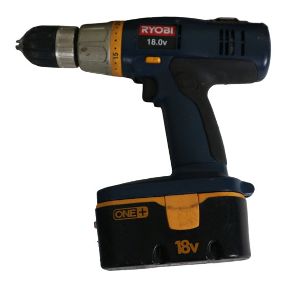
18 VOLT DRILL-DRIVER
2-SPEED
P200
Advertisement
Table of Contents

Related Manuals for Ryobi P200


Summary of Contents for Ryobi P200
- Page 1 Your drill-driver has been engineered and manufactured to Ryobi’s high standard for dependability, ease of operation, and operator safety. When properly cared for, it will give you years of rugged, trouble-free performance. WARNING: To reduce the risk of injury, the user must read and understand the operator’s manual before using this product.
-
Page 2: Table Of Contents
n Introduction ... 2 n General Safety Rules ... 3-4 n Specific Safety Rules... 4 n Safety Rules for Charger ... 5 n Symbols... 6-7 n Features... 8-9 n Assembly ... 10 n Operation... 11-17 n Maintenance ... 18-19 n Parts Ordering / Service ... 20 This tool has many features for making its use more pleasant and enjoyable. -
Page 3: General Safety Rules
Use battery only with charger listed. MODEL BATTERY PACK (P100) CHARGER (P110) P200 130255004 or 130224028 n Do not abuse the cord. Never use the cord to carry the charger. Keep cord away from heat, oil, sharp edges, or moving parts. -
Page 4: Specific Safety Rules
SERVICE n Tool service must be performed only by qualified re- pair personnel. Service or maintenance performed by unqualified personnel may result in a risk of injury. n Hold tool by insulated gripping surfaces when per- forming an operation where the cutting tool may con- tact hidden wiring. -
Page 5: Safety Rules For Charger
SAFETY RULES FOR CHARGER WARNING! READ AND UNDERSTAND ALL INSTRUCTIONS. Failure to follow all instructions listed below, may result in electric shock, fire and/or serious personal injury. n Before using battery charger, read all instructions and cautionary markings in this manual, on battery charger, battery, and product using battery to prevent misuse of the products and possible injury or damage. -
Page 6: Symbols
Some of the following symbols may be used on this tool. Please study them and learn their meaning. Proper interpreta- tion of these symbols will allow you to operate the tool better and safer. SYMBOL NAME Volts Amperes Hertz Watt Minutes Alternating Current Direct Current... - Page 7 The following signal words and meanings are intended to explain the levels of risk associated with this product. SYMBOL SIGNAL DANGER: WARNING: CAUTION: CAUTION: SERVICE Servicing requires extreme care and knowledge and should be performed only by a qualified service technician. For service we suggest you return the product to your nearest AUTHORIZED SERVICE CENTER for repair.
-
Page 8: Features
FEATURES PRODUCT SPECIFICATIONS Motor ...18 Volt DC Switch...Variable Speed No Load Speed ...0-350/0-1300/min. Charger Input ... 120 V, 60 Hz, AC only Charge Rate ...1 hour Torque... Maximum 400 in.lb. LEVEL TWO SPEED GEAR TRAIN (HI-LO) TORQUE ADJUSTMENT RING STORAGE AREA KEYLESS CHUCK... - Page 9 The switch trigger can be locked in the OFF position. This feature helps reduce the possibility of accidental starting when not in use. TWO-SPEED GEAR TRAIN A slide switch is located on top of the drill to select either LO (1) or HI (2) speed. FEATURES FORWARD/REVERSE SELECTOR...
-
Page 10: Assembly
Do not discard the packing material until you have care- fully inspected and satisfactorily operated the tool. n If any parts are damaged or missing, please call 1-800-525-2579 for assistance. PACKING LIST Drill-Driver Double-ended Bits (2) Operator’s Manual Warranty Registration Card ASSEMBLY... -
Page 11: Operation
LED on charger will come on. NOTE: If the charger does not charge the battery pack under normal circumstances, return both the battery pack and charger to your nearest Ryobi Authorized Service Center for electrical check. n Charge the battery pack only with a recommended charger. -
Page 12: Charging Hot Battery Pack
LED. After 30 minutes, reinsert the battery pack in the charger. If the green LED continues to remain on, return battery pack to your nearest Ryobi Authorized Service Center for checking or replacing. NOTE: This situation only occurs when continuous use of the tool causes the batteries to become hot. -
Page 13: Installing Bits
Also, raise the front of your drill slightly to keep the bit from falling out of the chuck jaws. n Insert your drill bit into the chuck the full length of the jaws. n Tighten the chuck jaws on the drill bit. To tighten, grasp and hold the collar of the chuck with one hand, while rotating the chuck body with your other hand. - Page 14 The drill has a two-speed gear train designed for drilling or driving at LO (1) or HI (2) speeds. A slide switch is located on top of your drill to select either LO (1) or HI (2) speed. When using drill in the LO (1) speed range, speed will decrease and unit will have more power and torque.
- Page 15 Two levels are recessed in the motor housing of the drill- driver. One is located on top, while the other is located on the end. They can be used to keep drill bits level during both horizontal and vertical drilling operations.
- Page 16 SCREWDRIVING TORQUE ADJUSTMENT (DRIVING POWER OF THE DRILL-DRIVER) See Figure 13. When using the drill-driver for various driving applications, it becomes necessary to increase or decrease the torque in order to help prevent the possibility of damaging screw heads, threads, workpiece, etc. In general, torque intensity should correspond to the screw diameter.
- Page 17 When drilling metals, use a light oil on the drill bit to keep it from overheating. The oil will prolong the life of the bit and increase the drilling action.
-
Page 18: Maintenance
Only the parts shown on the parts list are intended to be repaired or replaced by the customer. All other parts should be replaced at a Ryobi Authorized Service Center. MAINTENANCE CHUCK REMOVAL See Figures 15 - 17. - Page 19 TO RETIGHTEN A LOOSE CHUCK The chuck may become loose on spindle and develop a wobble. To tighten: n Lock the switch trigger by placing the direction of rotation selector in center position. n Open the chuck jaws. n Insert hex key into chuck and tighten chuck jaws securely. Tap hex key sharply with a mallet in a clockwise direction.
-
Page 20: Parts Ordering / Service
Ryobi Authorized Service Center. Be sure to provide all pertinent facts when you call or visit. Please call 1-800-525-2579 for your nearest Ryobi Authorized Service Center. You can also check our web site at www.ryobitools.com for a complete list of Authorized Service Centers.