Table of Contents
Advertisement
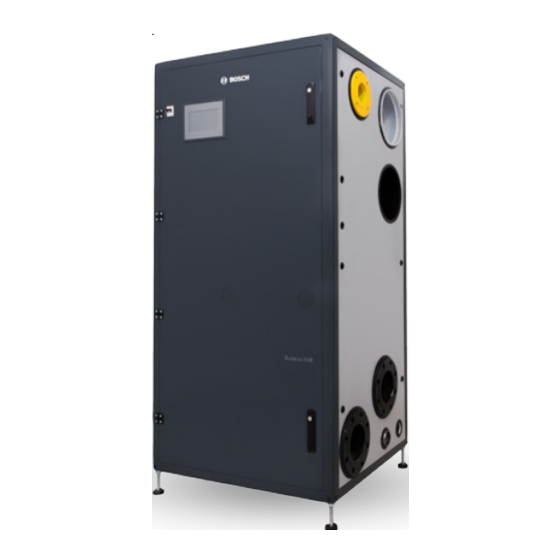
Gas Condensing Stainless Steel Boiler
BUDERUS SSB BOILER
SSB800 SA | SSB1000 SA | SSB1000 TL
Installation and Service Instructions for Contractors
WARNING:
If the information in these instructions is not followed exactly, a fire
or explosion may result causing property damage, personal injury or
death.
Do not store or use gasoline or other flammable vapors and liquids in
the vicinity of this or any other appliance.
WHAT TO DO IF YOU SMELL GAS:
• Do not try to light any appliance,
• Do not touch any electrical switch; do not use any phone in your
building,
• Immediately call your gas supplier from a neighbor's phone. Follow
the gas supplier's instructions,
• If you cannot reach your gas supplier, call the fire department.
Qualified installer, service agency or the gas supplier must perform
installation and service.
FOR YOUR SAFETY:
Improper installation and/or operation could create carbon monoxide
gas in flue gases which could cause serious injury, property damage,
or death. Improper installation and/or operation will void the warranty.
These instructions are available in English and French.
Please keep these instructions for future reference.
Advertisement
Table of Contents

Related Manuals for Bosch SSB800 SA


Summary of Contents for Bosch SSB800 SA
- Page 1 Improper installation and/or operation will void the warranty. These instructions are available in English and French. Please keep these instructions for future reference. Gas Condensing Stainless Steel Boiler BUDERUS SSB BOILER SSB800 SA | SSB1000 SA | SSB1000 TL Installation and Service Instructions for Contractors...
-
Page 2: Table Of Contents
Contents Introduction........31 . . . . . . . . . . . . . . Key to symbols and safety instructions Filling the condensate system . -
Page 3: Key To Symbols And Safety Instructions | 3
► Make sure that a licensed contractor / gas fitter installs the boiler, connects gas and vent, places the boiler in operation, connects the ► Only use original Bosch spare parts. Losses caused by the use of parts not supplied by Bosch are excluded from the Bosch warranty. -
Page 4: Product Description
► The boiler is intended only for the use for which it was specifically • The gas-fired condensing SSB boilers are designed to be used in designed and built. Bosch is hereby excluded from any liability for central heating systems. Any other use is prohibited. -
Page 5: Proper Use
2 .4 Environmental responsibility / disposal Environmental responsibility is one of the fundamental company policies of the Bosch Group. We regard quality of performance, economy and environmental responsibility as equal objectives. Environmental protection laws and regulations are strictly adhered to. -
Page 6: Dimensions And Connections
6 | Product description 2 .5 Dimensions and Connections 31.49 35.43 2" 8.54 9.88 3" 3" 5.31 7.48 10.63 A Flue exhaust 6” (160mm) E System supply 3” G Condensate outlet 1-1/2” (50mm) B Intake air 6” (160mm) F Relief valves outlet 2” (60mm) (adapter: PVC female coupling 1”) C Gas inlet 2”... -
Page 7: Technical Data
Product description | 7 2 .6 Technical data Unit SSB 800 SA SSB 1000 SA SSB 1000 TL Boiler Category ASME Sect.IV Type of Gas Natural Gas, Propane* BTU/hr 798,000 1,024,000 1,024,000 Max input rate (kW) (234) (300) (300) BTU/hr 79,800 100,000 100,000... -
Page 8: Main Components
8 | Product description 2 .7 Main components 17 11 12 13 [1] Heat exchanger [2] Flowmeter [3] Temp./pressure gauge [4] Relief valve [5] Pump [6] Manual stop valve [7] Water supply header [8] Water return header [9] Minimum water pressure switch [10] Main power switch [11] Fan [12] Gas manifold... -
Page 9: Efficiency Curves
Product description | 9 2 .8 Efficiency Curves 100% 100% input 30% input 20% input Return water temperature (°F)@36 Degree Rise Fig. 6 Efficiency Curves SSB 800 SA, 1000 SA, 1000 TL 6720866942 (2018/06) US... -
Page 10: Regulations
10 | Regulations - In the event that the requirements of this subdivision can not be Regulations met at the time of completion of installation, the owner shall have a period of thirty (30) days to comply with the above requirements; provided, however, that during said thirty (30) day period, a Observe all rules, regulations, standards and guidelines battery operated carbon monoxide detector with an alarm shall be... -
Page 11: Installation
The SSB is delivered strapped to a pallet, packed and protected in a as shown in Fig. 7. The minimum clearance dimensions, required cardboard carton. by BOSCH, are listed below. However, if Local Building Codes require additional clearances, these codes shall supersede BOSCH’s requirements. Minimum acceptable clearances required are as follows:... - Page 12 12 | Installation RECOMMENDED SERVICE CLEARANCES REQUIRED SERVICE COMBUSTIBLES 31.49” (800mm) 31.49” (800mm) 20” (**) 2” (**) (407mm) (51mm) 24” (*) 12” (*) 24” (*) 12” (*) (610mm) (610mm) (305mm) (305mm) FRONT FRONT 40” 40” (1016mm) (1016mm) (*) Excluding the side where the connections are made. (*) Excluding the side where the connections are made.
-
Page 13: Setting The Unit
Installation | 13 4 .2 .2 Setting the Unit In multiple unit installations, it is important to plan the position of each unit in advance. Sufficient space for piping connections and future service/ Remove the top and side carboard panels and the plastic film. Lift the maintenance requirements must also be taken into consideration. - Page 14 14 | Installation FLUE Fig. 11 SSB 1000 TL Cascade Installation The cascade installation of TL boilers should be carried out according to the following procedure (example: 2 boilers): [1] Set the position of one of the two boilers, connecting it to the system supply/return pipe; [2] Using a jackpallet, move the second boiler close to the first one, with a gap not less than 4ft;...
-
Page 15: Boiler Location
Installation | 15 4 .2 .3 Boiler location CAUTION: For freeze protection use only propylene • This boiler is suitable for indoor installations. glycol, with scale inhibitors, with a maximum volume • To operate properly and safely this boiler requires a continuous supply [concentration] of 40% of glycol. -
Page 16: Low Water Cutoff
16 | Installation 4 .4 .2 No Flow test procedure 3” Flanged Gas Connection To simulate a no water flow condition, the following steps should be followed: 10” PP Flue Venting • Turn power off to boiler • Disconnect module 1 pump power •... -
Page 17: Expansion Tank
(min. water flow Head available @ max. power for the system with T 54°F / at 44.4GPM 30°C) (recommended water flow @ max. power with T 36°F / 20°C) Flow rate / GPM Fig. 15 SSB800 SA Pressure drop 6720866942 (2018/06) US... - Page 18 18 | Installation SSB1000 SA ∆ p / Feet of Head Max. pump speed Head available for the system Head available at 37.8GPM for the system (min. water flow at 56.8GPM @ max. power (recommended with T 54°F / water flow @ 30°C) max.
-
Page 19: Condensate Drain And Piping
Installation | 19 4 .4 .7 Condensate drain and piping • The installation must have provisions for suitable drainage or collection of the condensate out of the boiler traps. The SSB boiler is designed to condense water vapor from the flue products. -
Page 20: Power Supply Cable Connection
20 | Installation 4 .4 .9 Power supply cable connection Loosen the screws of the cover and remove panel to access the internal connections shown in Fig. 23. The power supply cable can be inserted into the boiler using one of the three holes on the top panel (or one of the three holes on the back panel), as shown on fig. -
Page 21: Access To The Electrical Terminal Strips
Installation | 21 4 .5 .1 Enable/Disable(Room Thermostat Connection) The Room Thermostat (Enable/Disable) terminals (dry contacts) come Front Door pre-wired closed (jumped) from the factory. For connecting a room Cover (removed) thermostat, the jumper must be removed and the thermostat wires must Main Switch be connected to terminals 9 and 10, as shown in Fig. -
Page 22: Gas Supply Piping
CAUTION: Many of the soaps used for gas pipe leak testing are corrosive to metals. Therefore, piping must be rinsed The following are BOSCH’s recommendations for installation of gas thoroughly with clean water after leak checks have been pressure regulator, unless superseded by state and local codes and the completed. -
Page 23: Adjusting And Setting Co 2 Limits
Installation | 23 The gas-air ratio must always be set on the basis of a CO or O reading 4 .6 .5 Adjusting and setting CO limits taken at maximum nominal output and minimum nominal output using an • Insert a combustion analyzer probe into the test port shown in Fig. 28 electronic flue gas analyzer. -
Page 24: Venting And Air Piping System
24 | Installation 4 .7 Venting and air piping system List of adapters provided with the boiler for connection to CPVC or stainless steel venting systems: SSB boilers must be vented and supplied with combustion and ventilation air as described in this section. Model Description Manufacturer... - Page 25 Installation | 25 • The exhaust vent and the combustion air inlet lines must be supported to prevent sagging per the vent manufacturer’s instructions. • Do not mix components from different systems. The vent system could fail, causing leakage of flue products into the living space. Use only approved materials.
- Page 26 26 | Installation VENTING CONFIGURATIONS: The following figures show the acceptable piping installation for venting and combustion air for both, Stand Alone and Cascade configurations. EXHAUST EXHAUST BOILER BOILERS Fig. 32 All Combustion Air from Adjacent Indoor Spaces through indoor Combustion Air Openings EXHAUST EXHAUST BOILER...
- Page 27 Installation | 27 EXHAUST EXHAUST BOILER BOILERS Fig. 34 All Combustion Air From Outdoors - Inlet Air From Ventilated Crawl Space and Outlet Air to Ventilated Attic EXHAUST EXHAUST AIR DUCT AIR DUCT BOILER BOILERS AIR DUCT AIR DUCT Fig. 35 All Combustion Air from Outdoors through Horizontal Ducts 6720866942 (2018/06) US...
- Page 28 28 | Installation EXHAUST EXHAUST BOILER BOILERS Fig. 36 All Combustion Air from Outdoors through Single Combustion Air Opening EXHAUST EXHAUST BOILER BOILERS Fig. 37 Sealed Combustion located on same side with Exhaust (horizontal) 6720866942 (2018/06) US...
- Page 29 Installation | 29 EXHAUST EXHAUST BOILER BOILERS Fig. 38 Sealed Combustion located on same side with Exhaust (vertical) EXHAUST EXHAUST BOILER BOILERS Fig. 39 Sealed Combustion located on side wall 6720866942 (2018/06) US...
-
Page 30: Combustion Air
30 | Installation BOILER BOILERS EXHAUST EXHAUST Fig. 40 Exhaust located on side wall • It is not recommended to terminate vent above any door or window, 90° ELBOW - 6” 90° ELBOW - 10” Model condensate can freeze causing ice formations. equiv. -
Page 31: Ducted Combustion Air
Commissioning | 31 The combustion air must be free of: Commissioning • Permanent wave solutions; • Chlorinated waxes/cleaners; 5 .1 Introduction • Chlorine-based swimming pool chemicals; Before starting the boiler, the user must be correctly instructed by the • Calcium chloride installer, on how to operate the heater, in particular: •... -
Page 32: Warnings Concerning The Gas Supply
Warnings concerning the gas supply • The Touchscreen Control Panel will switch on. The Splash/Home screen consists of the BOSCH logo: When starting up the unit for the first time the following must be checked: • That the unit is supplied with the type of fuel that it is configured to use. -
Page 33: Minimum Water Flow (Heat Exchanger Protection)
Commissioning | 33 • After the Date & Time setting, if an outdoor probe is connected, the Reset Curve screen must be accessed (through the Settings screen) to set the curve parameters: CH Setpoint Maximum CH Setpoint Minimum Voltage ON/OFF Hysterese Fig. -
Page 34: Boilers' Cascade Installation And Start-Up (For Ssb 1000 Tl Only)
34 | Commissioning 5 .6 Boilers’ cascade installation and start-up (FOR SSB 1000 TL ONLY) Appendix E shows an example of SSB 1000 TL boilers installed in a cascade of three units. The built-in control system is capable to manage up to 4 boilers as a single, coordinated heating system. -
Page 35: Operation | 35
Installation” pag. 11 must be completed before attempting Fig. 52 BOSCH Screen to start the unit. The BOSCH logo is the entry point of the Control System. Just touching it, the system moves to the first operating screen, the Cascade one. 6 .2 Control panel description 6 .3 .2... -
Page 36: Boiler Screen
• Access the Module screen of the desired module, just touching it on the screen; Use the side buttons to perform the actions listed below: • Home button: move back to the BOSCH screen; • Performance button: move to the Performance screen of the boiler; • Stats button: not active;... -
Page 37: Error Screen
Operation | 37 6 .3 .6 Error Screen Shutdown_Period (factory setting) after the service reminder became active (message is displayed). For each boiler, the Error screen shows the list of the last 48 errors occurred on its own modules. The owner/user has a warning before the appliance will actually shutdown. -
Page 38: Appendix A - Wiring Diagram
38 | WIRING DIAGRAM Appendix A - Wiring diagram TRANSF.IGNITE R R ELAY TRANSF.IGNITE R R ELAY 101 102 104 105 106 107 108109 110 111 113 114 116 117 118 119 120121 122 123124 MAIN SUPPLY PUMP RELAY Main Pump 3 WAY CH Pump DHW/ ALARM... - Page 39 WIRING DIAGRAM | 39 Boiler DHW Tank Enable Supply Sensor Disable Sensor 6720866942 (2018/06) US...
- Page 40 40 | WIRING DIAGRAM WIRING DIAGRAM - MANAGING 6720866942 (2018/06) US...
- Page 41 WIRING DIAGRAM | 41 WIRING DIAGRAM - DEPENDENT 6720866942 (2018/06) US...
-
Page 42: Appendix B - Connection Diagram
42 | CONNECTION DIAGRAM Appendix B - Connection diagram CONNECTION DIAGRAM 905MN CONTROL BOARD Int. ionization Ignition 0-10V input Burner Open Thermostat interface or Spark Return Room Thermostat ON/OFF MAINS SUPPLY REMOTE DISPLAY PROG. INPUT 5: 1) T_Return DHW_STAT T_DHW_OUT/T_Store PROG. - Page 43 CONNECTION DIAGRAM | 43 CONNECTION DIAGRAM 905PB DISPLAY CONNECTION DIAGRAM 905PB DISPLAY 905PB05_3R Connector Function PC interface Connection to MN control/Modbus 905PB05_3R Display: RJ-11 Connector: RS485 / Mod BUS J25-1 J25-2 J25-3 J25-4 1: GND/VSS AL-BUS J25-5 2: ModBus_B (= Data -) +24V J25-6 3: ModBus_A (= Data +)
-
Page 44: Appendix C - Maintenance
Do not use methods that can cause • Repeat the same procedure for the other module. explosions! Spare parts list is available at BOSCH boilers website: (www.bosch-climate.us). CHECK EXHAUST AND COMBUSTION AIR PIPE SYSTEM Clear vent systems of any obstructions, corrosion, physical damage, CAUTION: Label all wires prior to disconnection when water stains, rust. -
Page 45: Appendix D - Troubleshooting Table
TROUBLESHOOTING TABLE | 45 Appendix D - Troubleshooting table Lockout Codes Error no . Error Description Checks Solutions E2PROM_READ_ERROR Internal software error Replace the power control board a- If the gas supply pressure is incorrect, it must be adjusted to the correct pressure;... - Page 46 46 | TROUBLESHOOTING TABLE Error no . Error Description Checks Solutions The 2 supply sensors deviate too TSUPPLY_DIFF_ERROR much for more than 60 seconds The 2 flue sensors deviate too much TFLUE_DIFF_ERROR for more than 60 seconds Too many automated filling attempts FILLING_TOO_MUCH in a short time period FILL_TIME_ERROR...
- Page 47 TROUBLESHOOTING TABLE | 47 Error no . Error Description Checks Solutions a- If the wiring is damaged, replace a- Check the integrity of the wire connections; b- Verify that the temperature sensor SUPPLY_OPEN Supply sensor open b- Check the supply temperature has the correct resistance values.
- Page 48 48 | TROUBLESHOOTING TABLE Error no . Error Description Checks Solutions T_EXCHANGE2_CLOSED Exchange 2 sensor shorted T_SELECTION1_CLOSED Selection 1 sensor shorted T_SELECTION2_CLOSED Selection 2 sensor shorted T_SELECTION3_CLOSED Selection 3 sensor shorted T_OPTIONAL1_CLOSED Optional 1 sensor shorted T_OPTIONAL2_CLOSED Optional 2 sensor shorted T_AMBIENT_CLOSED Ambient sensor shorted Watchdog fan configuration setting...
-
Page 49: Appendix E - Boiler Installation (Example Drawings)
BOILER INSTALLATION (EXAMPLE DRAWINGS) | 49 Appendix E - Boiler Installation (example drawings) SSB 800 SA, 1000 SA Stand Alone Installation 6720866942 (2018/06) US... - Page 50 50 | BOILER INSTALLATION (EXAMPLE DRAWINGS) SSB 1000 TL3 Cascade (3 units) Installation 6720866942 (2018/06) US...
- Page 51 BOILER INSTALLATION (EXAMPLE DRAWINGS) | 51 SSB 800 SA, 1000 SA Stand Alone Installation with Hot Water Storage Tank 6720866942 (2018/06) US...
- Page 52 52 | BOILER INSTALLATION (EXAMPLE DRAWINGS) SSB 1000 TL3 Cascade (3 units) Installation with Hot Water Storage Tank 6720866942 (2018/06) US...
-
Page 53: Appendix F - Exhaust Terminals And Air Inlet Clearances
EXHAUST TERMINALS AND AIR INLET CLEARANCES | 53 Appendix F - Exhaust terminals and Air inlet Clearances Direct vent (sealed combustion) / Fan assisted appliance (Room air for combustion) . See Note 1) [1] Forced air inlet X4 See Note 1) [2] Gravity air inlet X5 7 feet (2135 mm) [3] Exhaust terminal... - Page 54 54 | EXHAUST TERMINALS AND AIR INLET CLEARANCES Horizontal venting system (sealed combustion): Vertical venting system (sealed combustion): X ≥ 4” (102 mm); X > 12” (305 mm) Y ≥ 12” (305 mm) Y = 12” (305 mm) above maximum snow level or at least 24” whichever is greater Air intake Vent...
-
Page 55: Appendix G - Sensor Resistance
SENSOR RESISTANCE | 55 Appendix G - Sensor Resistance Vent terminals SENSOR RESISTANCE TABLE Temperature °F (°C) Resistance [Ω] Vent terminals Testing tolerance ±10% 32 (0) 27396 41 (5) 22140 50 (10) 17999 59 (15) 14716 68 (20) 12099 77 (25) 10000 86 (30) 8308... -
Page 56: Appendix H - De-Rating For Altitude Installation
56 | DE-RATING FOR ALTITUDE INSTALLATION Appendix H - De-rating for altitude installation When the appliance is installed at an altitude higher than 2000 ft, the fan speed must be set to the top of the available range in any case and a de-rating of the input capacity must be considered in function of the altitude combined with the total length of the vent and combustion air pipe as reported in the following table (input BTU/hr): SSB 800 SA... -
Page 57: Appendix I - Venting Size Data
VENTING SIZE DATA | 57 Appendix I - Venting size data SSB 800 SA T supply / return (°F): 176 / 140 T supply / return (°F): 104 / 86 Unit Maximum Input Minimum Input Maximum Input Minimum Input Exhaust gas mass (weight) lb/s 0,21 0,02... -
Page 58: 58 | Spare Parts
58 | Spare parts Spare parts Fig. 62 6720866942 (2018/06) US... - Page 59 Spare parts | 59 Item (→ Fig. 62) Description Q .ty per boiler Order number Plastic hinge ■ ■ ■ 7-738-006-397 Lock 90° turn for non-hinged panels ■ ■ ■ 7-738-006-395 Lock with handle for hinged panels ■ ■ ■ 7-738-006-396 Plastic disc ■...
- Page 60 60 | Spare parts Fig. 63 6720866942 (2018/06) US...
- Page 61 Spare parts | 61 Item (→ Fig. 63) Description Q .ty per boiler Order number Boiler power main switch ABB S202 32A ■ ■ ■ 7-738-006-402 Relay ■ ■ ■ 7-738-006-400 Relay holder ■ ■ ■ 7-738-006-399 Terminal strip (24 connections - high ■...
- Page 62 62 | Spare parts Fig. 64 6720866942 (2018/06) US...
- Page 63 Spare parts | 63 Item (→ Fig. 64) Description Q .ty per boiler Order number Water minimum pressure switch ■ ■ ■ 7-738-006-383 Ball valve 1''1/2 MM ■ ■ ■ 7-738-006-380 Ball valve 1''1/2 MM ■ ■ ■ 7-738-006-435 Flanged adapter 1"1/2 M for pump ■...
- Page 64 64 | Spare parts Fig. 65 6720866942 (2018/06) US...
- Page 65 Spare parts | 65 Item (→ Fig. 65) Description Q .ty per boiler Order number PP Flue manifold (6") ■ ■ 7-738-006-362 PP Flue manifold (10") ■ 7-738-006-363 Exhaust pipe (4") ■ ■ 7-738-006-360 Exhaust pipe (4") ■ 7-738-006-361 PP Condensate collector ■...
- Page 66 66 | Spare parts Fig. 66 6720866942 (2018/06) US...
- Page 67 Spare parts | 67 Item (→ Fig. 66) Description Q .ty per boiler Order number Nipple 3/4''-3/4" MM NPT ■ ■ ■ 7-738-005-008 Ball valve 3/4'' FF ■ ■ ■ 7-738-005-010 Stainless steel gas pipe ■ ■ ■ 7-738-006-367 Gas high pressure switch 1/4'' ■...
- Page 68 68 | Spare parts Fig. 67 6720866942 (2018/06) US...
- Page 69 Spare parts | 69 Item (→ Fig. 67) Description Q .ty per boiler Order number ■ ■ ■ 7-738-005-006 Silicone seal Fan/Burner head ■ ■ ■ 7-738-004-990 Burner tube flange ■ ■ ■ 7-738-005-403 Premix burner tube ■ ■ 7-738-005-406 Premix burner tube ■...
- Page 70 70 | Spare parts 19 18 Fig. 68 6720866942 (2018/06) US...
- Page 71 Spare parts | 71 Item (→ Fig. 68) Description Q .ty per boiler Order number Air vent valve 1/2'' ■ ■ ■ 7-738-004-936 LWCO sensor ■ ■ ■ 7-738-004-927 LWCO adapter ■ ■ ■ 7-738-004-928 High limit sensor ■ ■ ■...
- Page 72 United States and Canada Bosch Thermotechnology Corp. 50 Wentworth Avenue Londonderry, NH 03053 Tel. 603-552-1100 Fax 603-965-7581 www.boschheatingandcooling.com U.S.A. Bosch Thermotechnology Corp. reserves the right to make changes without notice due to continuing engineering and technological advances.