Table of Contents
Advertisement
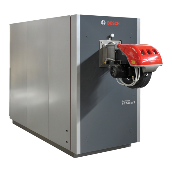
Stainless Steel Condensing Boiler
Buderus SB625WS/Buderus SB745WS
Low temperature condensing boilers for gas/oil fired power burners
Installation Instructions
Read these instructions carefully before installation and operation of the heating system.
UPON COMPLETION OF THE INSTALLATION THE INSTALLER MUST
INSTRUCT THE OWNER AND OPERATOR ON THE FUNCTIONALITY AND
THE PROPER OPERATION OF THE BOILER AND THE HEATING SYSTEM
THIS MANUAL SHOULD BE HANDED TO THE OWNER AND OPERATOR OF
THE APPLIANCE.
INSTALLER MUST REVIEW ALL SAFETY INSTRUCTIONS WITH THE
OWNER AND OPERATOR.
DANGER!
The installation instructions included in this Manual are intended solely for
use by a trained and certified installer, service company or the gas supply
company. If the information in this manual is not followed, a fire or explosion
may result causing property damage, personal injury, or death.
Have installation and service performed by a trained and certified
installer or service company, or the gas supply company.
Bosch recommends signing a service and maintenance contract with a
trained and certified installer or service company that covers annual
servicing and condition-based maintenance. Proper maintenance is a
fundamental requirement for safe and efficient operation and long
service life.
The boiler must be serviced annually including the main burner, ignition
burner, the entire venting system, and the combustion air supply. All
parts that show any signs of damage or corrosion must be replaced.
The owner and operator is responsible for the operational safety and
regulatory compliance of the heating system.
Improper installation, adjustment, alteration, service, or maintenance
can cause property damage, personal injury, or death. Refer to this
manual and consult a trained and certified installer or service company,
or the gas supply company before installation, service or maintenance.
Advertisement
Table of Contents

Related Manuals for Bosch Buderus SB625WS


Summary of Contents for Bosch Buderus SB625WS
-
Page 1: Installation Instructions
Have installation and service performed by a trained and certified installer or service company, or the gas supply company. Bosch recommends signing a service and maintenance contract with a trained and certified installer or service company that covers annual servicing and condition-based maintenance. Proper maintenance is a fundamental requirement for safe and efficient operation and long service life. -
Page 2: Table Of Contents
2 | Contents Contents 5.11.1 Draining the condensate ......26 Key to symbols and safety instructions ....3 5.11.2 Neutralizing the condensate . -
Page 3: Key To Symbols And Safety Instructions
Key to symbols and safety instructions | 3 If you smell flue gas Key to symbols and safety instructions ▶ Switch off the heating system by shutting off the emergency shut-off switch. Explanation of symbols ▶ Open windows and doors. ▶... - Page 4 4 | Key to symbols and safety instructions DANGER: Risk of personal injury or death from explosion! ▶ Work on gas components may only be carried out by a trained and certified installer or service company. ▶ Appliance installation, the connection of gas and vent piping, initial commissioning, electrical connections, and service and maintenance must only be carried out by a trained and certified installer or service company.
-
Page 5: Product Description
Product Description | 5 maintaining the condensing effect and the water heating time around the Product Description tube bundle for as long as possible. The boilers feature lightly pressurized combustion chambers for a The high efficiency SB Series boilers are designed to condense flue smoother burner action, and high temperature resistant, stainless steel gases through a unique three-pass construction for installation in a turbulators inside the tube bundle for maximum burner efficiency. -
Page 6: Intended Use
For a list of the approved burners, please contact power supply, servicing and repair may only be Bosch Thermotechnology Corp. carried out by an authorized heating engineer. The boiler can be operated with an aquastat, the Logamatic 4000, and ▶... -
Page 7: Suitable Fuels
Product Description | 7 secure the services of qualified licensed professionals for the shall remain with the appliance or equipment at the completion of the installation of hard wired carbon monoxide detectors. installation. – In the event that the side wall horizontally vented gas fueled Suitable fuels equipment is installed in a crawl space or an attic, the hard wired carbon monoxide detector with alarm and battery back-up may be... -
Page 8: Scope Of Delivery
8 | Product Description Scope of delivery Accessory box: The boiler accessory box contains The boilers SB625WS / SB745WS comes in two separate crates and one additional box. • Manifold • Pressure relief valve Boiler body crate: • Pressure/temperature gauge The instruction manual is an integral part of the boiler. -
Page 9: Dimensions And Specifications
Product Description | 9 Dimensions and specifications Values obtained with RS.../M-burners. 2.9.1 Dimensions 6 720 805 218-13.1T Fig. 4 Dimensions Description Unit SB625WS SB745WS 1050 1300 1550 A: Base width inch 27 3/16 27 3/16 29 1/2 29 1/2 31 1/8 31 1/8 37 7/16 37 7/16... -
Page 10: Technical Data
10 | Product Description 2.9.2 Technical Data Description SB625WS SB745WS 1050 1300 1550 Fuel Rated input (Nat. Gas) 1014 1314 1689 2200 3003 3754 4692 5443 (kW) (164.9) (230.9) (297.1) (385.0) (494.9) (644.7) (880.0) (1100.0) (1375.0) (1595.0) Rated input (#2 Oil) 12.0 15.7 21.4... -
Page 11: Water Connections
Product Description | 11 2.9.3 Water connections connected to suitable sub-systems. Water fittings are as specified in the following table. The boilers are designed and made for use in central heating installations, but can also be used for domestic hot water production if 2 3/4”... - Page 12 12 | Product Description Description SB625WS SB745WS 1050 1300 1550 1 – Heating supply inch 2 1/2 2 1/2 2 1/2 (DN) (65) (65) (65) (80) (100) (100) (125) (125) (150) (150) 2 – Heating return 1 inch 2 1/2 2 1/2 2 1/2 (Low Temperature)
-
Page 13: Water Treatment
Water treatment | 13 Water treatment The quality of the fill and top-up water is an essential factor for increased Chemical and physical requirements of heating system water efficiency, functional reliability, long service life and for maintaining the Parameters Unit of measure Heating water constant operational condition of a heating system. -
Page 14: Deposit Corrosion
14 | Water treatment specific areas, where temperature is the highest. A coating of limescale and joints in a water circuit are designed to resist pressure from of only 1 mm can cause severe overheating in metal parts and within, but not to resist a vacuum within) consequent damage through thermal stress. -
Page 15: Use Of Antifreeze
Water treatment | 15 In particular: • as temperature increases, oxygen becomes less watersoluble and bubbles begin to form. • CO2 (carbon dioxide) is generated as the carbonates of calcium and magnesium precipitate out. • the chemical oxidation of the metals in the system also generates hydrogen. -
Page 16: Transport
16 | Transport Transport WARNING: Risk of injury from carrying heavy loads and inadequately securing loads for transport. ▶ Use suitable means of transportation, e.g. several pallet trucks, a forklift truck, crane or heavy duty rollers. ▶ Secure the load against falling. ▶... -
Page 17: Installation
Installation | 17 Installation Boiler Clearances 6 720 805 218-52.1T Fig. 9 Installation site NOTICE: Risk of system damage through frost. ▶ Do not install the boiler outdoors; it is not designed to work outdoors and is not fitted with the necessary automatic anti-frost systems to do so. -
Page 18: Assembling The Paneling
18 | Installation SB625WS SB745WS 1050 1300 1550 Recommended Service inch 36,00 36,00 36,00 36,00 36,00 36,00 36,00 36,00 36,00 36,00 (mm) (915) (915) (915) (915) (915) (915) (915) (915) (915) (915) inch 64,00 64,00 65,00 73,00 81,00 88,00 101.00 111.00 119.00 122.00... - Page 19 Installation | 19 6 720 805 218-32.1T Fig. 10 Paneling [1-4] Top panels [12] Front side panel Front top panel [13] Side panel Rear side panel [14] Rear side panel Side panel [15] Bottom rear bracket Front side panel [16] Bottom rear panel Front trim panel [17] Top rear panel [10] Boiler frame...
-
Page 20: Refitting The Door Hinges
20 | Installation Refitting the door hinges 5.3.1 Changing the direction of door opening The boiler door hinges are factory fitted on the right of the door. If you The boilers are pre-fitted with three hinges so that the opening direction need to reverse the direction of opening, remove the boiler’s side panel of the door can be quickly reversed. - Page 21 Installation | 21 ▶ Insert a wrench through the top slot and hold the bushing [4] steady. System B (larger sizes) ▶ Open the door. ▶ With the aid of a small hacksaw or a file remove the knockout on the side opposite the leading edge of the door (both top and bottom).
- Page 22 22 | Installation ▶ Remove the plug taking care not to lose the compressed spring ▶ Remove the bolt [3] and the nuts [4]. inserted in the threaded tube. ▶ Remove the nuts [4] that secure the hinge plate [5] to the door ▶...
-
Page 23: Removing The Hinge Assembly "B
Installation | 23 5.3.2 Removing the hinge assembly “B” Burners ▶ Ensure that the side safety bolt is tight. Installing the burner ▶ Remove the main fixing bolt. Follow the burner manufacturer’s instructions when fitting the burner. ▶ With the door open, remove the hinge assembly ‘B’ (bushing, bolt, and washer) opposite the pivot side of the door. -
Page 24: Combustion Gas Exhaust
24 | Installation Combustion gas exhaust The flue gas exhaust and stack connection must be made in compliance with applicable laws and standards, using heat resistant, condensate resistant and stress resistant rigid pipe and sealed joints. The stack must be fitted with a condensate trap and drain and the flue gas exhaust pipe must be installed at a slope of at least 2°... -
Page 25: Venting Requirements
Installation | 25 Venting Requirements Code Required Vent Terminations The SB Boiler is a category II or IV appliance and the exhaust vent Horizontal Terminations: materials must be UL listed for use with a category IV appliance: • Vent terminations should be at least 4 feet below, 1 foot above or 4 operating temperatures of up to 240 °F, positive pressure, condensing feet horizontally from any window, door or gravity air inlet of a flue gas service. -
Page 26: Combustion Air From An Adjacent Room
26 | Installation The free area of the openings must be taken into account restrictions from the louvers and screens. The louver manufacturer should be consulted for the percentage of free area available. When free area is not known, metal louvers typically have 60-70% of free area, wooden louvers have between 20-25% of free area. - Page 27 Installation | 27 6 720 805 218-23.1T Fig. 24 Neutralization unit type NB-5LP Outlet fitting Inlet fitting NOTICE: The boiler room’s condensate drain pit must be located at a lower level than the fitting on the neutralization unit. NOTICE: All connecting hoses must be kept as straight and as short as possible.
-
Page 28: Commissioning
28 | Commissioning ▶ Maintain the minimum differential between the selected shutdown Commissioning temperature of the high limit safety cut-out, the temperature regulator, the maximum boiler water temperature and the maximum temperature demand ( table 12). NOTICE: Risk of boiler damage through contaminated combustion air. -
Page 29: Hydraulic Connection To The Heating System
Commissioning | 29 Example DHW demand (where the 4000 series controls the DHW If there are no varying return temperatures, only the low system): temperature flange needs to be connected. Sum of the set DHW temperature (140 °F) and parameter "Boiler rise" (40 °F) in the "DHW"... -
Page 30: Making The Electrical Connection
30 | Commissioning Making the electrical connection DANGER: Danger to life through electric shock! ▶ Before opening the boiler, isolate the heating system across all life phases and secure against unintentional reconnection. ▶ Carefully route the cables/leads and capillary tubes. ▶... -
Page 31: Fitting Temperature Sensors
Commissioning | 31 ▶ Insert the temperature sensor set as far as it will go into the test point (to the bottom). Use the mark to check whether the temperature sensors are correctly fitted. ▶ Secure the temperature sensor set in the test point with a sensor retainer. -
Page 32: Filling The Heating System
32 | Commissioning Filling the heating system Preparing the heating system for operation Observe the following points during commissioning: NOTICE: System damage through temperature ▶ The turbulators [2] are correctly positioned (horizontal) inside the stresses. heat exchanger tubes and the clips [1] are resting against the wall [3] ▶... -
Page 33: Commissioning Report
Commissioning | 33 6.11 Commissioning report The boiler can be operated with a gas or dual fuel burner. ▶ Carefully complete the commissioning report for the relevant approved burner. ▶ Sign all completed commissioning work and enter the date. Commissioning steps Comments (signature) Flush the heating system. -
Page 34: Shutting Down
34 | Shutting down Shutting down NOTICE: Risk of system damage through frost. When there is a frost, the heating system can freeze up if it is not operational, e.g. because of a fault shutdown. ▶ When there is a risk of frost, protect your heating system against freezing up. -
Page 35: Inspection And Maintenance
The first time you open the door, remove the spare hinge Only use genuine Bosch spare parts. You can order spare assembly ‘B’ (bushing, bolt, and washer) opposite the parts from the spare parts catalog. -
Page 36: Cleaning The Boiler
36 | Inspection and maintenance System B (larger size) ▶ Use a flue brush [3] or other suitable tool to clean inside the combustion chamber and the flue gas pipes. ▶ Put the door in its correct position. ▶ Tighten the main locking screws [1] until the packing starts to be compressed. -
Page 37: Checking And Correcting The Water Pressure
Inspection and maintenance | 37 ▶ If necessary, replace the gasket [1]. 8.4.2 Sealed unvented systems ▶ Clean all removed components, then follow the above steps in the NOTICE: System damage through frequent topping up. reverse order to refit them. Subject to the water quality, your heating system can be damaged through corrosion or scaling. -
Page 38: Inspection And Maintenance Reports
38 | Inspection and maintenance Inspection and maintenance reports The inspection and maintenance reports provide an overview of the Complete these reports after inspections and service. The report can required inspection and service steps that should be carried out also be used as copying template. annually. - Page 39 Inspection and maintenance | 39 Confirm professional inspection with signature, date and company stamp. Table 17 SB625WS/SB745WS 6 720 805 218 (2013/02)
-
Page 40: Spare Parts
40 | Spare parts Spare parts The following replacement parts are available from Bosch Thermotechnology Corp. SB625WS-160/220/290 ( Fig. 38) Item no. Description Article number -160 -220 -290 Burner door complete 7738003072 Burner door complete 7738003073 Burner plate gasket 7738003078... - Page 41 Spare parts | 41 6 720 805 218-54.1T Fig. 38 Spare parts SB625WS-160/220/290 SB625WS/SB745WS 6 720 805 218 (2013/02)
- Page 42 42 | Spare parts SB625WS-370/480/640 ( Fig. 39) Item no. Description Article number -370 -480 -640 Burner door complete 7738003073 Burner door complete 7738003074 Burner plate gasket 7738003079 Burner plate gasket 7738003080 Burner plate 7738003084 Burner plate 7738003121 Burner plate 7738003085 Gasket sight glass 7738003089...
- Page 43 Spare parts | 43 12 13 6 720 805 218-55.1T Fig. 39 Spare parts SB625WS-370/480/640 SB625WS/SB745WS 6 720 805 218 (2013/02)
- Page 44 44 | Spare parts SB745WS-800/1050/1300/1550 ( Fig. 40) Item no. Article number -800 -1050 -1300 -1550 Burner door complete 7738003075 Burner door complete 7738003076 Burner door complete 7738003077 Burner plate gasket 7738003080 Burner plate gasket 7738003082 Burner plate 7738003085 Burner plate 7738003086 Burner plate 7738003087...
- Page 45 Spare parts | 45 Item no. Article number -800 -1050 -1300 -1550 Flue brush 7738003059 Sealing rope 7738003166 Table 20 Spare parts SB745WS-800/1050/1300/1550 SB625WS/SB745WS 6 720 805 218 (2013/02)
- Page 46 46 | Spare parts 6 720 805 218-56.1T Fig. 40 Spare parts SB745WS-800/1050/1300/1550 6 720 805 218 (2013/02) SB625WS/SB745WS...
-
Page 47: Troubleshooting
Troubleshooting | 47 Troubleshooting Problem Cause Troubleshooting The boiler does not reach its set temperature. Heat exchanger dirty. ▶ Clean the flue gas pipes. Heat exchanger and burner mismatched. ▶ Check specifications and settings. Insufficient gas flow burner. ▶ Check and adjust the burner. Control thermostat problem. -
Page 48: Environmental Protection/Disposal
48 | Environmental protection/disposal Environmental protection/disposal Environmental protection is one of the fundamental company policies of the Bosch Group. We regard quality of performance, economy and environmental protection as equal objectives. Environmental protection laws and regulations are strictly adhered to. -
Page 49: Glossary
Glossary | 49 Glossary Appearance Alkalinity The appearance of water depends on the presence of sediment, in M-alkalinity or total alkalinity represents the sum total of all alkaline salts suspension or in colloidal form, and on the presence of dissolved (bicarbonates, carbonates, hydrates and alkaline phosphates) present substances that create easily identifiable conditions like turbidity, in a water sample. - Page 50 50 | Glossary Checks The following table lists the sampling frequencies and sampling locations for the various types of heating system. As is the case with checks for water parameters, it is the responsibility of the system operator to ensure that any water treatment systems are Type of system Hot water functioning properly, in compliance with instructions and at the...
- Page 51 | 51 Notes SB625WS/SB745WS 6 720 805 218 (2013/02)