
Related Manuals for Bosch DOW 1171


Summary of Contents for Bosch DOW 1171
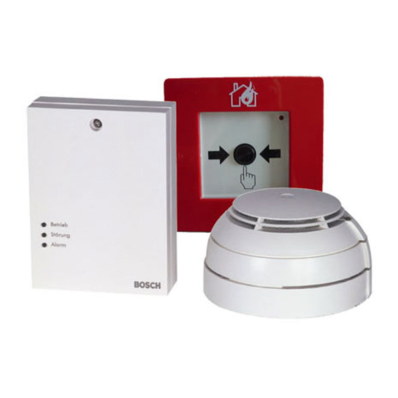
- Page 1 Radio Frequency Fire Detection System DOW 1171, FK 110 LSN, SMF121 Operation Guide...
-
Page 3: Table Of Contents
Manually Operating the FK 100 LSN RF Interface Module Exchanging and Adding Radio Components Exchanging the FK 100 LSN RF Interface Module and DOW 1171 and SMF121 RF Detectors Adding DOW 1171 and SMF121 RF Detectors using WinPara / FSP‑5000‑RPS... -
Page 4: Notes
Installation must only be carried out by authorized specialist personnel. To guarantee the resistance to interference of the devices, only installation material approved for installation by Bosch ST may be used. All devices must be installed in dry areas. Caution! Electrostatic discharge (ESD)! Electronic components could become damaged. -
Page 5: Short Information
The RF fire detection system consists of 1 FK 100 RF Interface Module and up to 30 RF smoke detectors (DOW 1171 RF Smoke Detector and/or SMF121 RF Manual Call Point). As an LSN element, FK 100 RF Interface Module is switched in a loop or stub line and forms the interface between the RF smoke detectors and the fire panel. -
Page 6: System Overview
Figure 3.2: FK 100 LSN configuration closed Housing cover Lower part of housing Cable bushing LED operation, fault and alarm Figure 3.3: FK 100 LSN configuration open Radio module Reed contact PC board Tamper contact Connection terminals 2016.04 | 6.0 | 4.998.120.885 Operation Guide Bosch Sicherheitssysteme GmbH... -
Page 7: Dow 1171 Rf Smoke Detector
The interface module has a tamper contact, a reed contact for manual activation of the configuration mode and three LEDs for the operating status display. DOW 1171 RF Smoke Detector Figure 3.4: DOW 1171 configuration closed and open Detector Bases Bayonet ring... - Page 8 The RF manual call point consists of the SMF121 Manual Call Point and the SMF6120 Detector Base. The detector base contains the radio module and the inserts and connections for the batteries. 2016.04 | 6.0 | 4.998.120.885 Operation Guide Bosch Sicherheitssysteme GmbH...
-
Page 9: Led Functions
(Interface module opened or detector twisted out of base) Normal mode Display Timing diagram [ms] Rapid flashing 4 Hz 1000 Slow flashing 0.5 Hz 1000 3.4.2 DOW 1171 RF Smoke Detector LED Flash cycle Timing diagram [ms] Meaning 1680 Once every System search 2 s 1920 Once every New logon 2 s... - Page 10 Radio Frequency Fire Detection System Flash cycle Timing diagram [ms] Meaning Three times Field strength every 1 s moderate Twice every Field strength low 1 s Once every Field strength very low 1 s 2016.04 | 6.0 | 4.998.120.885 Operation Guide Bosch Sicherheitssysteme GmbH...
-
Page 11: Installation/Configuration Notes
Lime sand brick 6 dB Sand lime brick planning elements 10 dB Wood framed or wood paneled walls 10 dB Damp brick wall 10 dB Coated gypsum plasterboard (double wall) 15 dB Steel-reinforced concrete 30 dB Bosch Sicherheitssysteme GmbH Operation Guide 2016.04 | 6.0 | 4.998.120.885... - Page 12 In the figure beneath, the FK 100 LSN Interface Module is installed under a reinforced concrete ceiling (white), the dividing walls are made from concrete (gray). The RF detectors are placed at different positions with and without a visual line to the RF interface module. DOW 1171 DOW 1171 15 m...
-
Page 13: Planning A Rf Fire Detection System With Dzw 1171 Radio Test Unit
If the LED (5) on module B goes out, the RF interface module or RF detector installation location is outside the radio range. Bosch Sicherheitssysteme GmbH Operation Guide 2016.04 | 6.0 | 4.998.120.885... -
Page 14: Installing The Rf Fire Detection System
∅ 6 mm 76.5 ∅ 4.5 x 25 mm 61.5 Figure 5.9: FK 100 LSN RF Interface Module Dimensions 2016.04 | 6.0 | 4.998.120.885 Operation Guide Bosch Sicherheitssysteme GmbH... -
Page 15: Installing Dow 1171 Rf Smoke Detector
Connection of FK 100 LSN RF Interface Module to the Fire Panel, page 18. Use hose clips to secure the connection cable to the bars (5) to relieve strain. Installing DOW 1171 RF Smoke Detector Notice! Do not connect the batteries in the RF smoke detector base until the RF interface module is permanently connected to the power supply. - Page 16 When installing the base, ensure without fail that the LED display is always visible from the reconnaissance route. For precise aligning when installing, the position of the display LED (1) is marked on the base. Figure 5.12: Aligning the DOW 1171 RF Smoke Detector along the Reconnaissance Route LED display Reconnaissance route 2016.04 | 6.0 | 4.998.120.885...
-
Page 17: Installing The Smf121 Rf Manual Call Point
Then wire up the SMF6120 Base to the SMF121 RF Manual Call Point in line with chapter Connection of SMF121 RF Manual Call Point to SMF6120 Base, page 19. Then install the SMF121 RF Manual Call Point on the base. Bosch Sicherheitssysteme GmbH Operation Guide 2016.04 | 6.0 | 4.998.120.885... -
Page 18: Wiring
Do not insert the terminal blocks until the RF interface module has been commissioned; as this simplifies the commissioning procedure (see chapter Commissioning the FK 100 LSN RF Interface Module via WinPara / FSP-5000-RPS, page 21. 2016.04 | 6.0 | 4.998.120.885 Operation Guide Bosch Sicherheitssysteme GmbH... -
Page 19: Connection Of Smf121 Rf Manual Call Point To Smf6120 Base
Figure 6.15: Connection of SMF121 RF Manual Call Point to SMF6120 Base Break out the pre-punched cable feed on the SMF121 RF Manual Call Point. Wire up the connection cable to the terminal block of the RF manual call point. Bosch Sicherheitssysteme GmbH Operation Guide 2016.04 | 6.0 | 4.998.120.885... -
Page 20: Commissioning A Rf Fire Detection System
(see chapter Commissioning the FK 100 LSN RF Interface Module via WinPara / FSP-5000-RPS, page 21) and then the individual RF detectors must be logged into the RF interface module (see chapter Commissioning DOW 1171 and SMF121 RF Detectors, page 21). -
Page 21: Commissioning The Fk 100 Lsn Rf Interface Module Via Winpara / Fsp-5000-Rps
WinPara / FSP-5000-RPS. Ensure that all the DOW 1171 and SMF121 RF Detectors are installed in the appropriate base and at the actual installation location when logging in to the RF interface module. -
Page 22: Logging In The Smf121 Rf Manual Call Points To The Rf Interface Module
Flash rate per second Field strength Meaning 4 times High Secure transfer => Detector is positioned correctly 3 times Average Twice Insecure transfer => Detector must be repositioned Once Very low 2016.04 | 6.0 | 4.998.120.885 Operation Guide Bosch Sicherheitssysteme GmbH... -
Page 23: Manually Operating The Fk 100 Lsn Rf Interface Module
Now log in all the RF detectors one after the other to the RF interface module as described in chapter Commissioning DOW 1171 and SMF121 RF Detectors, page 21. After all the RF detectors have been logged in, and the flashing to display the field strength has gone out on the last detector, activate the reed contact in the RF interface module again, by moving a magnet along the left side of the interface module housing. -
Page 24: Exchanging And Adding Radio Components
Exchange DOW 1171 / SMF. Wait until the red LED on the DOW 1171 RF Smoke Detector or the green LED on the PC board in the SMF6120 Detector Base as well as the green LED on the FK 100 LSN RF Interface Module are flashing rapidly. - Page 25 After approx. 1 second, the red LED lights up briefly and shows that the RF detectors can now be added. To log in the RF detectors, follow the instructions in chapter Logging in DOW 1171 RF Smoke Detectors to the RF Interface Module, page 21 or chapter Logging in the SMF121 RF Manual Call Points to the RF Interface Module, page 22.
-
Page 26: Maintenance And Service
Under optimum application conditions, lithium batteries have an operational life of approx. 5 years. However, Bosch ST recommends that you replace the batteries after approx. 4 years, as part of a scheduled inspection. Batteries are changed during normal operation. It is not necessary to make any settings on the fire panel. -
Page 27: Order Information
SOLO100 Telescopic Access Pole, 1 to 3.4 m, can be extended 4.998.112.069 with up to 3 SOLO101 fixed extension poles SOLO101 fixed extension pole, 1 m 4.998.112.070 Detector exchanger for the DOW 1171 RF smoke detector 4.998.120.144 (Suitable for service pole from Siemens) Testing Aerosol for Optical Smoke Detectors 12 Pc F.01U.301.104... -
Page 28: Technical Data
Housing color light-gray, RAL 9002 Dimensions (H x W x D) 135 x 100 x 35.7 mm Weight Approx. 200 g DOW 1171 RF Smoke Detector Power supply 2 x 9 V lithium batteries Battery service life approx. 5 years Average current consumption 0.07 mA... - Page 29 116.3 x 116.3 x 42 mm – SMF121 installed on SMF6120 125 x 125 x 56.5 mm Weight – SMF121 Approx. 150 g – SMF6120 Approx. 350 g – SMF121 installed on SMF6120 Approx. 500 g Bosch Sicherheitssysteme GmbH Operation Guide 2016.04 | 6.0 | 4.998.120.885...
- Page 31 Bosch Sicherheitssysteme GmbH Robert-Bosch-Ring 5 85630 Grasbrunn Germany www.boschsecurity.com © Bosch Sicherheitssysteme GmbH, 2016...