Table of Contents
Advertisement
Advertisement
Table of Contents

Related Manuals for Bosch D1256


Summary of Contents for Bosch D1256
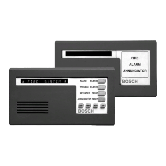
- Page 1 Fire Command Center/Fire Alarm Annunciators D1256/D1257 Installation Instructions...
- Page 2 D1256/D1257 D1256/D1257 Installation Instructions 74-06925-000-H Page 2 © 2004 Bosch Security Systems...
-
Page 3: Table Of Contents
Description.....................................7 3.2.1 Display.....................................7 3.2.2 Audible Tones ..................................7 3.2.3 Switch Settings..................................8 Installation ......................................9 Mounting the D1256 and D1257 ............................9 4.1.1 Mounting Locations ................................9 Wiring the D1256 and D1257............................9 Programming the Control Panel ............................ 10 4.3.1 Command Center Assignments............................. 10 4.3.2 Area Text....................................10 4.3.3... - Page 4 Figure 7: Example 6 – User Interface for D7212, D7212G, D7412, D7412G, D9112, D9412, D9412G and D9124 (using the D9112LTB-EX or D9412GLTB) ......................14 Tables Table 1: D1256/D1257 Installation Instructions Organization....................5 Table 2: D1256/D1257 Specifications............................6 Table 3: Key to Figure 1 ..................................7 Table 4: Switch Address Settings ..............................8...
-
Page 5: Introduction
Before installing the D1256 or D1257, you should be familiar with the Operation and Installation Guide and Program Entry Guide for the control panel you are using. When using the D1256 or D1257 with the D9112B1 Control Panel, the firmware must be Revision 2.1 or higher. -
Page 6: Specifications
16 character vacuum fluorescent display. Each character is a 14-segment unit. Soft Display blue color. Operating Temperature 0°C to +50°C (+32°F to +122°F) Relative Humidity 5% to 85% @ +30°C (86°F) Table 2: D1256/D1257 Specifications D1256/D1257 Installation Instructions 74-06925-000-H Page 6 © 2004 Bosch Security Systems... -
Page 7: Overview
3.2.2 Audible Tones Both the D1256 and D1257 have a built-in speaker that produces several distinct warning tones. The speaker volume can be changed by adjusting the potentiometer (see Figure 1). Turn the potentiometer clockwise to increase and counterclockwise to decrease the volume. You cannot connect external annunciation devices to the annunciators. -
Page 8: Table 4: Switch Address Settings
[TROUBLE SILENCE] key on the D1256. 3.2.3 Switch Settings A 6-position switch located under the D1256 and D1257 cover allows you to select the address of each annunciator and silence the keypad encoding tones (see Figure 1). To access the switches: Remove the front cover. -
Page 9: Table 5: Wiring Connections
Installation Installation Mounting the D1256 and D1257 The D1256 and D1257 are low profile, surface-mounted units molded in durable red plastic. They can be mounted using the following optional packages: • D56 Command Center Keypad Conduit Box (protected surface or flush mount) •... -
Page 10: Figure 2: Example 1 - Area Text
Key Stroke: [1][2][5][6][0][0][E]. This custom function is programmed as the first Menu item. It is executed when the [ALARM SILENCE] key is pressed on the D1256. The key stroke entry of 125600E is seen by the control panel as a valid passcode entry in the area having the authority level to silence a ringing fire bell in the area. -
Page 11: Figure 4: Example 3 - Menu/Function List
Key Stroke: [A][4][C]. This custom function is programmed as the second item in the Menu and is executed whenever the [TROUBLE SILENCE] key is pressed on the D1256. This entry is equivalent to the execution of a [COMMAND][4] at the D1256. -
Page 12: Figure 5: Example 4 - Passcode Worksheet
Bosch Security Systems recommends programming the first ten menu items as indicated in Table 6. The first four menu items must be programmed as indicated in Table 6 for the D1256 to function properly. The first four keys on the D1256 annunciator execute the first four menu items turned on at the command center address. -
Page 13: Figure 6: Example 5 - User Interface For D7212B1, D9112B1, And D9124 (Using The D9112Ltb)
Force Arm Area O/C Restricted O/C Perimeter O/C Send Duress Passcode Arm Passcode Disarm Figure 6: Example 5 – User Interface for D7212B1, D9112B1, and D9124 (using the D9112LTB) D1256/D1257 Installation Instructions © 2004 Bosch Security Systems Page 13 74-06925-000-H... -
Page 14: Figure 7: Example 6 - User Interface For D7212, D7212G, D7412, D7412G, D9112, D9412, D9412G And D9124 (Using The D9112Ltb-Ex Or D9412Gltb)
D9124 (using the D9112LTB-EX or D9412GLTB) Note: Please make sure that CF 128 to 131 and any other functions that you are using in the menu are programmed E (Enabled) not P (Passcode Required). D1256/D1257 Installation Instructions 74-06925-000-H Page 14 © 2004 Bosch Security Systems... -
Page 15: Command Center Functions
It is suggested that the items below be included in the menu. • #9 View Event Memory • #10 View Point Status • #12 Fire Test • #21 View Log • #29 Remote Program • #32 Display Rev D1256/D1257 Installation Instructions © 2004 Bosch Security Systems Page 15 74-06925-000-H... - Page 16 Function List for D1256 and D1255 addresses. Remember to enable functions only as appropriate for the command center at the address. As the D1256 does not have numeric keys, it can not be used to access functions requiring a passcode.