Table of Contents
Advertisement
Quick Links
Advertisement
Chapters
Table of Contents

Related Manuals for Omron ZX-LDA11


Summary of Contents for Omron ZX-LDA11
- Page 1 Smart Sensors ZX Series Operation Manual OMRON Corporation Cat. No. Z157-E1-02...
- Page 2 Introduction Thank you for purchasing an OMRON ZX-series Smart Sensor. We hope you will fully utilize this product and its performance for many years to come. The ZX-series Smart Sensor is a laser product designed specifically as a sensing device. To ensure safety, read this manual carefully before using the Sensor. In addition, keep this manual in an easily accessible location for quick reference when needed.
- Page 3 WAY CONNECTED WITH THE PRODUCTS, WHETHER SUCH CLAIM IS BASED ON CONTRACT, WARRANTY, NEGLIGENCE, OR STRICT LIABILITY. In no event shall responsibility of OMRON for any act exceed the individual price of the product on which liability is asserted. IN NO EVENT SHALL OMRON BE RESPONSIBLE FOR WARRANTY, REPAIR, OR OTHER CLAIMS REGARDING THE PRODUCTS UNLESS OMRON’S ANALYSIS...
- Page 4 Performance data given in this document is provided as a guide for the user in determining suitability and does not constitute a warranty. It may represent the result of OMRON’s test conditions, and the users must correlate it to actual application requirements. Actual performance is subject to the OMRON Warranty and Limitations of Liability.
-
Page 5: For Your Safety
For Your Safety For Your Safety Notation for Safety Information The following conventions are used to indicate and classify precautions in this manual. Always heed the information provided with them. Failure to heed precautions can result in injury to people or damage to property. Indicates a potentially hazardous situation which, if not avoided, will result in minor or moderate injury, or may result in serious... - Page 6 (4) The user should return the product to OMRON for all repair and servicing. (5) As for countries other than those of Europe and the U.S.A., observe the regu-...
- Page 7 Laser Safety Requirements from Regulations and Standards EN60825-1 “Safety of Laser Products, Equipment Classification, Requirements and User’s Guide” • Summary of Manufacturer’s Requirements Requirements; Classification Sub-clause Class 1 Class 2 Class 3A Class 3B* Class 4 Description of Safe under Low power;...
- Page 8 Laser Safety Note 1. The above table is intended to provide a convenient summary of requirements. See text of this standard for complete requirements. 2. AEL: Accessible Emission Limit The maximum accessible emission level permitted within a particular class. For your reference, see ANSI Z136.1-1993, Section 2. Symbol and border: black Background: yellow Figure A Warning label - Hazard symbol...
- Page 9 Laser Safety Requirements Class (see note 1) IIIa IIIb Remote control connector Key control Emission indica- (See note (See note 10.) 10.) Beam attenuator Reset (See note 13.) Performance (specific purpose products) Medical (See note (See note (See note Surveying, level- ing, alignment Demonstration (See note...
- Page 10 Laser Safety 6. Warning statement label. 7. CAUTION logotype. 8. Requires means to measure level of laser radiation intended to irradiate the body. –2 9. CAUTION if 2.5 mW cm or less, DANGER if greater than 2.5 mW cm 10.Delay required between indication & emission. 11.Variance required for Class IIb or IV demonstration laser products and light shows.
- Page 11 Laser Safety Control measures Classification ✩ ✩ ✩ ✩ Interlocks on Protective Housing (4.3.2) ✩ ✩ ✩ ✩ Service Access Panel (4.3.3) Key Control (4.3.4) • Viewing Portals (4.3.5.1) Collecting Optics (4.3.5.2) Totally Open Beam Path (4.3.6.1) Limited Open Beam Path (4.3.6.2) Enclosed Beam Path (4.3.6.3) None is required if 4.3.1 and 4.3.2 fulfilled Remote Interlock Connector...
- Page 12 Laser Safety Control measures Classification Eye Protection (4.6.2) • Protective Windows (4.6.3) Protective Barriers and Curtains • • (4.6.4) Skin Protection (4.6.5) Other Protective Equipment (4.6.5) Use may be required Warning Signs and Labels (4.7) • • (Design Requirements) Service and Repairs (4.8) LSO Determination Modification of Laser Systems LSO Determination...
- Page 13 Laser Safety Comparison of Classifications between FDA and ANSI Class FDA definition ANSI description Class I/1 Limits applicable to devices that have emissions in A Class 1 laser is considered to be in- the ultraviolet, visible, and infrared spectra, and capable of producing damaging radia- limits below which biological hazards have not tion levels during operation and...
- Page 14 Laser Safety • FDA Aperture Label Class II Caution logo type Certification and Caution identification label logo type Aperture label Certification and Identification Label Note: Use of controls, adjustments, or procedures other than those specified here- in may result in hazardous radiation exposure.
-
Page 15: Precautions
Precautions Precautions Ratings and Performance (1) Conform to the specified ratings and performance. Refer to "6-1 Ratings/Specifications" • Do not impose voltage exceeding the rated voltage, otherwise the Sen- sor may be damaged. • When supplying power to the Sensor, make sure that the polarity of the power is correct, otherwise, the Sensor may be damaged. - Page 16 Precautions • Locations subject to direct sunlight or near heating equipment. • Locations subject to high humidity. • Locations where the Sensor would accumulate dust, dirt, metallic pow- der, etc. • Locations subject to corrosive or flammable gases. • Locations subject to exposure to organic solvents, water, oil, etc. •...
-
Page 17: Table Of Contents
Table of Contents For Your Safety ..............i Laser Safety................ ii Precautions................ xi SECTION 1 Before Use............ 1 1-1 Names of Sensor Parts ................2 1-2 External Amplifier Unit I/O..............5 1-3 I/O Circuit Diagrams ................6 1-4 Connections ....................8 1-5 Installation ....................11 1-6 Settings Required before Application...........15 SECTION 2 Outline of Operation ........ - Page 18 Visual Aids The following icons are used to aid you in finding specific types of information. Indicates useful information. POINT Note: Indicates precautions to be observed during operation. Indicates section numbers where related information can be found.
- Page 19 Displayed Form of Alphabet Letters The letters of the alphabet are displayed digitally in the following forms.
-
Page 21: Section 1 Before Use
1-1-3 Amplifier Units ...............4 1-1-4 Calculating Unit ..............4 1-2 External Amplifier Unit I/O..............5 1-3 I/O Circuit Diagrams................6 1-3-1 NPN Amplifier Unit: ZX-LDA11..........6 1-3-2 PNP Amplifier Unit: ZX-LDA41..........7 1-4 Connections ..................8 1-4-1 Sensor Head and Amplifier Unit ..........8 1-4-2 Connecting Cable and Sensor Head........8 1-4-3 Extension Cables ..............9... -
Page 22: Names Of Sensor Parts
Names of Sensor Parts Section 1-1 Names of Sensor Parts 1-1-1 Reflective Sensor Heads A Reflective Sensor Head is used for displacement measurements. Emitter/receiver (optical filter ) Display area Output cable (with connector) Range indicators (green) Range Indicator Lighting Status... -
Page 23: Through-Beam Sensor Heads
Names of Sensor Parts Section 1-1 1-1-2 Through-beam Sensor Heads A Through-beam Sensor Head is used for length measurements and con- sists of two main parts: An Emitter and a Receiver. Emitter Laser ON indicator (green) Light Lit when light is emitted. emitter Emitter-side Emitter... -
Page 24: Amplifier Units
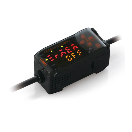
Names of Sensor Parts Section 1-1 1-1-3 Amplifier Units Controls Display area Input cable (with connector) Output cable Connector The current/voltage switch (Cover opens and closes.) for the linear output is on the bottom. 1-1-4 Calculating Unit Display area Connector Connection Indicators: Light when the Calculating Unit is connected to Amplifier Units. -
Page 25: External Amplifier Unit I/O
External Amplifier Unit I/O Section 1-2 External Amplifier Unit I/O The following functions are allocated to the external I/O lines. Brown 12 to 24 VDC Blue GND (0 V) White HIGH output Green PASS output Gray LOW output Black Linear output Shield Linear output GND Pink... -
Page 26: I/O Circuit Diagrams
I/O Circuit Diagrams Section 1-3 I/O Circuit Diagrams 1-3-1 NPN Amplifier Unit: ZX-LDA11 Brown 12 to 24 VDC Load Load White HIGH output Load 12 to 24 VDC Green PASS output Gray LOW output Blue GND (0 V) Laser OFF input... -
Page 27: Pnp Amplifier Unit: Zx-Lda41
I/O Circuit Diagrams Section 1-3 1-3-2 PNP Amplifier Unit: ZX-LDA41 Brown 12 to 24 VDC White HI G H output PASS output Green 12 to 24 VD C Load Gray LOW output Load Load GND (0 V) Blue Laser OFF input Pink Purple Timing input... -
Page 28: Connections
Connections Section 1-4 Connections 1-4-1 Sensor Head and Amplifier Unit 1. Insert the output cable connector of the Sensor Head into the in- put cable connector of the Amplifier Unit until the connector ring locks into place. 2. When disconnecting the Sensor Head, hold the connector ring and Amplifier Unit connector and pull them straight out. -
Page 29: Extension Cables
Connections Section 1-4 1-4-3 Extension Cables When extending Sensor Head and Amplifier Unit cables, use the following special cables (order separately). • 1-m Cable: ZX-XC1A • 4-m Cable: ZX-XC4A • 8-m Cable: ZX-XC8A • 9-m Cable: ZX-XC9A (for use with Reflective Sensors only) Connect the Extension Cable between the Connecting Cable and the Amplifier Unit. - Page 30 Connections Section 1-4 4. Slide the other Amplifier Unit on the DIN Track until the Calculat- ing Unit connector connects securely to the Amplifier Unit con- nector. The connectors should click into place. Note 1. Connect the connectors only after mounting the Units to the DIN Track.
-
Page 31: Installation
Installation Section 1-5 Installation 1-5-1 Reflective Sensor Heads Install the Sensor Head using the screws provided with it. For the ZX-LD use M3 screws. For the ZX-LD30V use M4 screws. Mounting Hole Size Refer to 6-2-1 Reflective Sensor Heads. Note 1. Secure the connector so that it is not subjected to vibration or shock. 2. -
Page 32: Through-Beam Sensor Heads
Installation Section 1-5 1-5-2 Through-beam Sensor Heads Installation • The Emitter and Receiver must be installed in the same direction to align the laser beam. Mounting hole Receiver Mounting hole Correct Emitter Incorrect • Tighten the screws to a torque of 0.3 N⋅m or less. M3 screws M3 screws ZX-LT001/LT005... - Page 33 Installation Section 1-5 Optical Axis Adjustment • Attach the optical axis adjustment seal provided with the Sensor Head to the front of the Emitter. Adjust the laser beam radiated from the Emitter so that it is aligned with the center of the cross on the seal. Always remove the seal after completing the adjustment.
-
Page 34: Amplifier Unit
Installation Section 1-5 Note 1. Use the same tightening torque for the left and right screws. The laser beam may be distorted if the tightening torque is not the same. 2. If the screws are tightened at a stronger torque than specified, the screw holes may be damaged. -
Page 35: Settings Required Before Application
Settings Required before Application Section 1-6 Settings Required before Application These settings are required only for a Through-beam Sensor Head. The settings for the auto-scale, reference incident level, and linear output are required before application. Perform the settings in the following order: 1-6-1 Auto-scale ↓... -
Page 36: Reference Incident Level
Settings Required before Application Section 1-6 3. Confirmation Select both the display unit and either the incident level or the in- tercepted amount, and then press the ENT Key to confirm the settings. An example is shown below for measuring the incident level in millimeters. -
Page 37: Linear Output
Settings Required before Application Section 1-6 1-6-3 Linear Output The default linear output settings are listed in the following table. These settings are set at the factory and also after initializing the settings. Default linear Operation after setting reference incident level output setting Voltage ±... - Page 38 Settings Required before Application Section 1-6 5. Perform the following steps to set the linear output. Monitor focus Press the ENT Key to select the voltage output. Use UP/DOWN/LEFT/RIGHT Keys to set the focus value of the first point to 5 V at 100%. Press the ENT Key to move to the monitor focus for the second point .
-
Page 39: Section 2 Outline Of Operation
SECTION 2 Outline of Operation This section describes the overall flow of operation. 2-1 Part Names and Functions ...............20 2-2 Outline of Key Operations ..............21 2-3 Procedures for Reflective Sensor Heads ..........22 2-3-1 Positioning and Setting Threshold Values......22 2-3-2 Setting Various Functions ...........22 2-4 Procedures for Through-beam Sensor Heads ........24 2-4-1 Positioning and Setting Threshold Values......24 2-4-2 Setting Various Functions ...........24... -
Page 40: Part Names And Functions
Part Names and Functions Section 2-1 Part Names and Functions Zero reset indicator (green) Enable indicator (green) Laser ON indicator (green) Judgement indicators HIGH (orange) PASS (green) LO W (yellow) See note 2. See note 2. Sub-display Main display Threshold value, incident level, resolution, etc. Measured value, function, etc. -
Page 41: Outline Of Key Operations
Outline of Key Operations Section 2-2 Outline of Key Operations Mode: RUN Mode: T Threshold value See note 1. Manual setting Display selection Digit position Timing input Numeric value Reset input See note 3. Threshold value Zero reset confirmation/Teaching Mode: FUN See note 2. -
Page 42: Procedures For Reflective Sensor Heads
Procedures for Reflective Sensor Heads Section 2-3 Procedures for Reflective Sensor Heads 2-3-1 Positioning and Setting Threshold Values Manual Setting 3-4-2 Inputting Threshold Values Directly Automatic Setting Workpiece surface positioning: Position Teaching in 3-4-1 Teaching Unknown size workpiece judgement: Two-point Teaching in 3-4-1 Teaching Judging workpiece with uneven surfaces, warped workpieces, or mov- ing workpieces: Automatic Teaching in 3-4-1 Teaching... - Page 43 Procedures for Reflective Sensor Heads Section 2-3 Detecting minute changes: Special Functions (Fun) 3-5-10 Differentiation Function Reversing display order: Special Functions (disp) 3-5-11 Display Reverse Function Minimizing the current consumption of the Amplifier Unit: Special Functions (disp) 3-5-12 ECO Display Function Changing the number of digits on the display: Special Functions (disp) 3-5-13 Limiting the Number of Display Digits...
-
Page 44: Procedures For Through-Beam Sensor Heads
Procedures for Through-beam Sensor Heads Section 2-4 Procedures for Through-beam Sensor Heads 2-4-1 Positioning and Setting Threshold Values Manual Setting 3-7-2 Inputting Threshold Values Directly Automatic Setting Workpiece surface positioning: Position Teaching in 3-7-1 Teaching Unknown size workpiece judgement: Two-point Teaching in 3-7-1 Teaching Judging workpiece with uneven surfaces, warped workpieces, or mov- ing workpieces: Automatic Teaching in 3-7-1 Teaching... - Page 45 Procedures for Through-beam Sensor Heads Section 2-4 Changing output current or voltage range: Special Functions (Set) 3-8-9 Monitor Focus Function Detecting minute changes: Special Functions (Fun) 3-8-10 Differentiation Function Reversing display order: Special Functions (disp) 3-8-11 Display Reverse Function Minimizing current consumption of the Amplifier Unit: Special Functions (disp) 3-8-12 ECO Display Function Changing the number of digits on the display:...
-
Page 46: Outline Of Functions
Outline of Functions Section 2-5 Outline of Functions 2-5-1 RUN Mode Displays Distance Distance Distance Distance Distance Main display See note. Threshold Incident Voltage Current Resolution value level Note: The incident level is displayed in Intensity Mode (9999 max.). 2-5-2 T Mode Direct threshold value input Position teaching... - Page 47 Outline of Functions Section 2-5 See note 2. Operation Special Initialization Auto-scale See note 1. Functions selected under Special appear at this level. Differentiation Intensity Mode Monitor focus function See note 3. Display Limited number mode A − B reverse of display digits A + B Settings for...
- Page 48 Outline of Functions Section 2-5 Memo...
-
Page 49: Section 3 Descriptions Of Functions
SECTION 3 Descriptions of Functions This section describes the functions that can be set. 3-1 ZX-L Series................31 3-1-1 ZX-L Series Outline ............32 3-1-2 Sensor Heads ..............32 3-1-3 Amplifier Units..............32 3-1-4 Calculating Unit..............32 3-1-5 Channel Numbers of Amplifier Units.........33 3-2 Hardware Functions ................34 3-2-1 Inputs ................34 3-2-2... - Page 50 3-5-12 ECO Display Function ............69 3-5-13 Limiting the Number of Display Digits.......69 3-5-14 Setting for Non-measurement...........69 3-5-15 Zero Reset Memory Function ...........70 3-5-16 Gain Switch...............70 3-5-17 Key Lock Function ............70 3-6 Through-beam Sensor Heads: RUN Mode Functions.....71 3-6-1 Sub-display Changes............71 3-6-2 Reference Incident Level Setting Function .......72 3-6-3...
-
Page 51: Zx-L Series
ZX-L Series Section 3-1 ZX-L Series The ZX Series are the first of the Smart Sensors from OMRON. In the ZX Series, ZX-L Laser Sensors include displacement (Reflective) and length- measuring (through-beam) sensors. The lineup is as follows: Sensing center... -
Page 52: Zx-L Series Outline
ZX-L Series Section 3-1 3-1-1 ZX-L Series Outline The ZX-L Series consists of high-accuracy, advanced sensors designed to use a laser light emitted onto the sensing object to measure the distance between the sensing object and the Sensor Head, judge the sensing object surface status, position, and obtain width measurements. -
Page 53: Channel Numbers Of Amplifier Units
ZX-L Series Section 3-1 3-1-5 Channel Numbers of Amplifier Units When two Amplifier Units are connected and set in the normal display direction, 1CH (channel 1) is used by the Unit on the top and 2CH (channel 2) is used by the Unit on the bottom. Calculating Unit... -
Page 54: Hardware Functions
Hardware Functions Section 3-2 Hardware Functions 3-2-1 Inputs Power Supply (12 to 24 VDC) A 12 to 24-VDC power supply is connected to the power supply terminal. When using an Amplifier Unit with a PNP output, the power supply terminal is also the common I/O terminal for all I/O except for the linear output. -
Page 55: Outputs
Hardware Functions Section 3-2 The following values are output according to the setting for non-measure- ment. Setting for non-measurement Output CLAMP KEEP Judgement outputs All OFF The values immediately before the non-measure- Maximum output Linear output ment status are kept. value is held. - Page 56 Hardware Functions Section 3-2 Hysteresis Measured Value HIGH threshold Measured value LOW threshold Judgement Outputs HIGH output PASS output LOW output Operating point Releasing point Relationship between Measured Value and Judgement Outputs Linear Output The linear output can be switched between current output and voltage out- put.
-
Page 57: Performance
Hardware Functions Section 3-2 3-2-3 Performance Linearity The linearity indicates how much linearity is maintained by the linear out- put against the displacement amount (incident level). The linearity is evalu- ated as the percentage of full scale (FS) represented by the deviation from an ideal straight line. -
Page 58: Reflective Sensor Heads: Run Mode Functions
Reflective Sensor Heads: RUN Mode Functions Section 3-3 Reflective Sensor Heads: RUN Mode Functions 3-3-1 Sub-display Changes Items shown on the sub-display can be selected. When Intensity Mode is OFF, the threshold values (HIGH/LOW), voltage value, current value, incident level, or resolution can be selected. When Intensity Mode is ON, the threshold values (HIGH/LOW), voltage value, current value, or resolution can be selected. - Page 59 Reflective Sensor Heads: RUN Mode Functions Section 3-3 Display value (mm) For current output Time 20 (mA) When zero is reset at 90 mm −4 −1 For voltage output Display value (mm) For current output −30 Time 20 22 (mA) When the displayed value is out of range, select KEEP or CLAMP for the setting for non-measurement.
- Page 60 Reflective Sensor Heads: RUN Mode Functions Section 3-3 Example: Use Zero Reset to Evaluate the Height of a Step in the Sensing Object Sensor Head This height must be evaluated. Sensing object All that is necessary is to reset zero at the point indicated by the arrow while measuring.
-
Page 61: Reflective Sensor Heads: T Mode Functions
Reflective Sensor Heads: T Mode Functions Section 3-4 Reflective Sensor Heads: T Mode Functions 3-4-1 Teaching “Teaching” is used to perform calculations in the Sensor to automatically determine the threshold values by creating an actual operating environ- ment and detecting objects. After teaching, the threshold values can be precisely adjusted or teaching can be performed as many times as required. - Page 62 Reflective Sensor Heads: T Mode Functions Section 3-4 Two-point Teaching The middle point between the first teaching point and the second point is set as a threshold. With two-point teaching, small steps, such as a sheet of paper, can be measured. Press the ENT Key Press the ENT for a long time...
-
Page 63: Inputting Threshold Values Directly
Reflective Sensor Heads: T Mode Functions Section 3-4 Automatic Teaching For automatic teaching, measurements are performed while the RIGHT Key and the ENT Key are pressed at the same time. The center value between maximum and minimum values is set as a threshold. The threshold value is set when the keys are released. -
Page 64: Reflective Sensor Heads: Fun Mode Functions
Reflective Sensor Heads: FUN Mode Functions Section 3-5 Reflective Sensor Heads: FUN Mode Functions 3-5-1 Scaling Scaling is used to arbitrarily change the display value for the actual dis- tance. The display value for any distance can be input or changed. When scaling one point, the display value offset is changed;... - Page 65 Reflective Sensor Heads: FUN Mode Functions Section 3-5 Inverting Display Values When inverting the display values is set, the display values will be in an inverse relationship to the reference values. Normally, the more the distance between Sensor and sensing object increases, the larger the display value becomes.
- Page 66 Reflective Sensor Heads: FUN Mode Functions Section 3-5 Offsetting Display Values: One-point Scaling A Use one-point scaling to offset the display values. Input the distance to be displayed for the current measurement point. When you input only one point for scaling, only the offset is changed without changing the range of display values.
- Page 67 Reflective Sensor Heads: FUN Mode Functions Section 3-5 Displaying the Height of the Sensing Object: One-point Scaling B The height of the sensing object can be displayed by using one-point scal- ing and inverting the display values. When the display values are inverted, the larger the displacement, the smaller the display value.
- Page 68 Reflective Sensor Heads: FUN Mode Functions Section 3-5 Correcting Display Values to Match Actual Distances: Two-point Scaling A Display values can be corrected if there is a discrepancy between the actual distance from the Sensor Head to the sensing object and the value displayed on the Amplifier Unit.
- Page 69 Reflective Sensor Heads: FUN Mode Functions Section 3-5 Displaying Arbitrary Values: Two-point Scaling B Any display value can be achieved using the same method as for the two- point scaling A. Any value can be input for two points to change the range and offset of display values (see following figure).
- Page 70 Reflective Sensor Heads: FUN Mode Functions Section 3-5 Measuring Thicknesses of Sensing Objects: One-point Scaling C The thickness of a sensing object can be measured by using two-sensor operation and one-point scaling (and inverting display values). Perform the two-sensor operation A+B to display the sum of the measured values for two Sensor Heads.
-
Page 71: Number Of Samples To Average
Reflective Sensor Heads: FUN Mode Functions Section 3-5 3-5-2 Number of Samples to Average The number of samples to average is the number of data points used to average data measured by the Sensor. Increase the number of samples to average to decrease variations in order to achieve fine positioning and judgement. -
Page 72: Hysteresis Setting
Reflective Sensor Heads: FUN Mode Functions Section 3-5 3-5-3 Hysteresis Setting The hysteresis of the threshold values (hysteresis width) can be set. Any value can be input directly or the hysteresis can be set automatically. Refer to 4-5-6 FUN Mode Status Transitions. If the hysteresis cannot be set, refer to 5-2-4 Unable to Set Hysteresis. - Page 73 Reflective Sensor Heads: FUN Mode Functions Section 3-5 Normal Mode (Hold Not Enabled) In Normal Mode, the measured value is always displayed and output. The timing input is disabled and no hold function will operate. Current (mA) Always outputs the measured value. Measured value = Display value = Output value...
- Page 74 Reflective Sensor Heads: FUN Mode Functions Section 3-5 Peak Hold In Peak Hold Mode, measurements are performed while the timing input is ON, and the maximum value during the sampling period will be the output value. Hold Mode starts when the power is turned ON, immediately after chang- ing to RUN or T Mode, or immediately after the reset input is turned OFF.
- Page 75 Reflective Sensor Heads: FUN Mode Functions Section 3-5 Bottom Hold In Bottom Hold Mode, measurements are performed while the timing input is ON, and the minimum value during the sampling period will be the out- put value. Hold Mode starts when the power is turned ON, immediately after chang- ing to RUN or T Mode, or immediately after the reset input is turned OFF.
- Page 76 Reflective Sensor Heads: FUN Mode Functions Section 3-5 Sample Hold In Sample Hold Mode, the measured result when the timing input is turned ON will be the output value. Hold Mode starts when the power is turned ON, immediately after chang- ing to RUN or T Mode, or immediately after the reset input is turned OFF.
- Page 77 Reflective Sensor Heads: FUN Mode Functions Section 3-5 Peak-to-peak Hold In Peak-to-peak Hold Mode, measurements are performed while the timing input is ON, and the difference between the maximum value and the mini- mum value in the sampling period will be the output value. Hold Mode starts when the power is turned ON, immediately after chang- ing to RUN or T Mode, or immediately after the reset input is turned OFF.
- Page 78 Reflective Sensor Heads: FUN Mode Functions Section 3-5 Self-peak Hold In Self-peak Hold Mode, measurements are performed while the mea- sured value is larger than or equal to the self-trigger level, and the maxi- mum value in the period will be the output value. Hold Mode starts when the power is turned ON, immediately after chang- ing to RUN or T Mode, or immediately after the reset input is turned OFF.
- Page 79 Reflective Sensor Heads: FUN Mode Functions Section 3-5 Self-bottom Hold In Self-bottom Hold Mode, measurements are performed while the mea- sured value is smaller than or equal to the self-trigger level, and the mini- mum value in the period will be the output value. Hold Mode starts when the power is turned ON, immediately after chang- ing to RUN or T Mode, or immediately after the reset input is turned OFF.
- Page 80 Reflective Sensor Heads: FUN Mode Functions Section 3-5 Judgement Outputs in Hold Mode The judgement outputs during Hold Mode are based on the value that is held (= the display value). Therefore, when using Hold Mode, the linear output, judgement outputs, and display value remain unchanged before the end of the next sampling period.
-
Page 81: Timer
Reflective Sensor Heads: FUN Mode Functions Section 3-5 3-5-5 Timer Timer Time The time set for the timer is the delay time for the ON-delay timer, the delay time for the OFF-delay timer, or the pulse width for the one-shot timer. Set the time according to the requirements of the control system (e.g., PLC). - Page 82 Reflective Sensor Heads: FUN Mode Functions Section 3-5 The timing chart is shown below. Normal output (Timer disabled.) OFF-delay timer ON-delay timer One-shot timer Changes for Different Types of Timer and PASS Output (Timer Time: t The timer process is applied to the PASS output. This means that an ON- is applied to the HIGH output when the OFF-delay timer of delay timer of t is applied to the PASS output when the measured value changes from...
-
Page 83: Two-Sensor Operation
Reflective Sensor Heads: FUN Mode Functions Section 3-5 3-5-6 Two-sensor Operation Two-sensor operation enables mutual operation using the measured val- ues from the two Sensor Heads to generate final outputs. Two kinds of out- puts, A−B or A+B, can then be selected. When two-sensor operation is selected, any scaling that is set for each Sensor Head will be reset to the defaults. -
Page 84: Initializing Settings
Reflective Sensor Heads: FUN Mode Functions Section 3-5 A − B The difference between the measured values of the two Sensor Heads is the final output. The measured value of the 1CH Amplifier Unit is B and the measured value of the 2CH Amplifier Unit is A. A + B The sum of measured values of the two Sensor Heads is the final output. -
Page 85: Monitor Focus Function
Reflective Sensor Heads: FUN Mode Functions Section 3-5 Default Settings The settings are initialized to the default setting made at the factory. The default settings are listed in the following table. Mode Function Initial value Scaling values Maximum display value: Maximum sensing distance Minimum display value: Minimum sensing distance... - Page 86 Reflective Sensor Heads: FUN Mode Functions Section 3-5 3-5-8 Monitor Focus Function The linear output range and inclination for display values can be specified. These are set by defining two output values for specified display values. Refer to 4-5-10 Setting the Monitor Focus. When the monitor focus function cannot be set correctly, refer to 5-2-2 Unable to Set Monitor Focus.
- Page 87 Reflective Sensor Heads: FUN Mode Functions Section 3-5 Linear output voltage For these settings: − 4 80 mm: − 4 V 120 mm: 4 V Linear output voltage 60 80 120 140 Sensor display value − 4 (mm) For these settings: Sensor display value 70 mm: 3 V 120 mm: −2 V...
-
Page 88: Intensity Mode
Reflective Sensor Heads: FUN Mode Functions Section 3-5 3-5-9 Intensity Mode The Intensity Mode can be selected either when using distance values for display and output values or when using the received intensity (light level). When the Intensity Mode is entered, the following are changed: Threshold values (HIGH and LOW), hysteresis (hysteresis width), self-trigger level, monitor focus function values, and the data for the received amount. -
Page 89: Display Reverse Function
Reflective Sensor Heads: FUN Mode Functions Section 3-5 3-5-11 Display Reverse Function The display direction of the digital displays can be selected. Select either forward or backward according to the mounting direction of the Amplifier Unit. Refer to 4-5-11 Special FUN Mode Settings Related to Dis- plays. -
Page 90: Zero Reset Memory Function
Reflective Sensor Heads: FUN Mode Functions Section 3-5 3-5-15 Zero Reset Memory Function If required, the zero reset level can be stored when the power supply is turned OFF. Enable this function when the previous zero reset level must be restored when the power supply is turned ON again. When this function is enabled, the zero reset level data will be written in nonvolatile memory (EEPROM). -
Page 91: Through-Beam Sensor Heads: Run Mode Functions
Through-beam Sensor Heads: RUN Mode Functions Section 3-6 Through-beam Sensor Heads: RUN Mode Functions 3-6-1 Sub-display Changes Items shown on the sub-display can be selected. The threshold values (HIGH/LOW), voltage value, current value, incident level, and resolution can be selected. •... -
Page 92: Reference Incident Level Setting Function
Through-beam Sensor Heads: RUN Mode Functions Section 3-6 3-6-2 Reference Incident Level Setting Function This function registers and stores the current incident level as the refer- ence incident level. This function is set under the condition that none of the beam is intercepted. - Page 93 Through-beam Sensor Heads: RUN Mode Functions Section 3-6 Display value (mm) For current output Time 20 (mA) When zero is reset at 2 mm −4 −1 For voltage output Display value (mm) For current output −2 Time 20 22 (mA) When the displayed value is out of range, select KEEP or CLAMP for the setting for non-measurement.
- Page 94 Through-beam Sensor Heads: RUN Mode Functions Section 3-6 Example: Use Zero Reset to Evaluate the Height of a Step in the Sensing Object Receiver Sensing object Emitter This height must be evaluated. All that is necessary is to reset zero at the point indicated by the arrow while measuring.
-
Page 95: Through-Beam Sensor Heads: T Mode Functions
Through-beam Sensor Heads: T Mode Functions Section 3-7 Through-beam Sensor Heads: T Mode Functions 3-7-1 Teaching “Teaching” is used to perform calculations in the Sensor to automatically determine the threshold values by creating an actual operating environ- ment and detecting objects. After teaching, the threshold values can be precisely adjusted or teaching can be performed as many times as required. - Page 96 Through-beam Sensor Heads: T Mode Functions Section 3-7 Two-point Teaching The middle point between the first teaching point and the second point is set as a threshold. With two-point teaching, small steps, such as a sheet of paper, can be measured. Teaching point 1 Sensor Head Emitter Sensor Head Receiver...
- Page 97 Through-beam Sensor Heads: T Mode Functions Section 3-7 Automatic Teaching For automatic teaching, measurements are performed while the RIGHT Key and the ENT Key are pressed at the same time. The center value between maximum and minimum values is set as a threshold. The threshold value is set when the keys are released.
-
Page 98: Inputting Threshold Values Directly
Through-beam Sensor Heads: T Mode Functions Section 3-7 3-7-2 Inputting Threshold Values Directly The threshold values can be directly input into the sub-display. Note: Generally, any value can be input. The judgement outputs, however, will not operate for thresholds that are outside the measurement range. Also, the decimal point cannot be changed. -
Page 99: Through-Beam Sensor Heads: Fun Mode Functions
Through-beam Sensor Heads: FUN Mode Functions Section 3-8 Through-beam Sensor Heads: FUN Mode Functions 3-8-1 Auto-scaling Select either millimeters or a percentage for the display on the main dis- play and whether the incident level or intercepted amount is displayed. The current incident level (intercepted amount) is automatically scaled, displayed, and output with respect to the reference incident level. -
Page 100: Scaling
Through-beam Sensor Heads: FUN Mode Functions Section 3-8 3-8-2 Scaling Scaling is used to arbitrarily change the display value for the measured value. The display value for any measured value can be input or changed. When scaling one point, the display value offset is changed; the display value range is not changed. - Page 101 Through-beam Sensor Heads: FUN Mode Functions Section 3-8 Inverting Display Values When inverting the display values is set, the display values will be in an inverse relationship to the reference values. Normally, the more the measured value between Sensor and sensing object increases, the larger the display value becomes.
- Page 102 Through-beam Sensor Heads: FUN Mode Functions Section 3-8 Offsetting Display Values: One-point Scaling A Use one-point scaling to offset the display values. Input the width to be dis- played for the current measurement point. When you input only one point for scaling, only the offset is changed with- out changing the range of display values.
- Page 103 Through-beam Sensor Heads: FUN Mode Functions Section 3-8 Correcting Display Values to Match Actual Width: Two-point Scaling A Display values can be corrected if there is a discrepancy between the actual incident beam width and the value displayed on the Amplifier Unit. When actual widths are known, they are input at two points to correct the range and offset of display values (see following figure).
- Page 104 Through-beam Sensor Heads: FUN Mode Functions Section 3-8 Display value (mm) Previous value of 3.6 mm is displayed as 4.0 mm Previous value of 2.2 mm is displayed as 2.0 mm. Actual incident beam width (mm)
- Page 105 Through-beam Sensor Heads: FUN Mode Functions Section 3-8 Displaying Arbitrary Values: Two-point Scaling B Any display value can be achieved using the same method as for the two- point scaling A. Any value can be input for two points to change the range and offset of display values (see following figure).
- Page 106 Through-beam Sensor Heads: FUN Mode Functions Section 3-8 Displaying the Width of the Sensing Object: One-point Scaling B The width of the sensing object can be measured by using two-sensor operation and one-point scaling, and inverting the display values. First, perform the two-sensor operation A+B to display the sum of the mea- sured values for the two Sensor Heads.
-
Page 107: Number Of Samples To Average
Through-beam Sensor Heads: FUN Mode Functions Section 3-8 Display value (mm) Display value 50.0 Actual value measured Actual incident beam width (mm) 3-8-3 Number of Samples to Average The number of samples to average is the number of data points used to average data measured by the Sensor. -
Page 108: Hysteresis Setting
Through-beam Sensor Heads: FUN Mode Functions Section 3-8 3-8-4 Hysteresis Setting The hysteresis of the threshold values (hysteresis width) can be set. Any value can be input directly or the hysteresis can be set automatically. Refer to 4-5-6 FUN Mode Status Transitions. If the hysteresis cannot be set, refer to 5-2-4 Unable to Set Hysteresis. -
Page 109: Hold Functions
Through-beam Sensor Heads: FUN Mode Functions Section 3-8 3-8-5 Hold Functions The hold functions extract, output, and display data for specific points, such as the maximum value, the minimum value, etc. There are six hold functions: Peak hold, bottom hold, sample hold, peak- to-peak hold, self-peak hold, and self-bottom hold. - Page 110 Through-beam Sensor Heads: FUN Mode Functions Section 3-8 Peak Hold In Peak Hold Mode, measurements are performed while the timing input is ON, and the maximum value during the sampling period will be the output value. Hold Mode starts when the power is turned ON, immediately after chang- ing to RUN or T Mode, or immediately after the reset input is turned OFF.
- Page 111 Through-beam Sensor Heads: FUN Mode Functions Section 3-8 Bottom Hold In Bottom Hold Mode, measurements are performed while the timing input is ON, and the minimum value during the sampling period will be the out- put value. Hold Mode starts when the power is turned ON, immediately after chang- ing to RUN or T Mode, or immediately after the reset input is turned OFF.
- Page 112 Through-beam Sensor Heads: FUN Mode Functions Section 3-8 Sample Hold In Sample Hold Mode, the measured result when the timing input is turned ON will be the output value. Hold Mode starts when the power is turned ON, immediately after chang- ing to RUN or T Mode, or immediately after the reset input is turned OFF.
- Page 113 Through-beam Sensor Heads: FUN Mode Functions Section 3-8 Peak-to-peak Hold In Peak-to-peak Hold Mode, measurements are performed while the timing input is ON, and the difference between the maximum value and the mini- mum value in the sampling period will be the output value. Hold Mode starts when the power is turned ON, immediately after chang- ing to RUN or T Mode, or immediately after the reset input is turned OFF.
- Page 114 Through-beam Sensor Heads: FUN Mode Functions Section 3-8 Self-peak Hold In Self-peak Hold Mode, measurements are performed while the mea- sured value is larger than or equal to the self-trigger level, and the maxi- mum value in the period will be the output value. Hold Mode starts when the power is turned ON, immediately after chang- ing to RUN or T Mode, or immediately after the reset input is turned OFF.
- Page 115 Through-beam Sensor Heads: FUN Mode Functions Section 3-8 Self-bottom Hold In Self-bottom Hold Mode, measurements are performed while the mea- sured value is smaller than or equal to the self-trigger level, and the mini- mum value in the period will be the output value. Hold Mode starts when the power is turned ON, immediately after chang- ing to RUN or T Mode, or immediately after the reset input is turned OFF.
- Page 116 Through-beam Sensor Heads: FUN Mode Functions Section 3-8 Judgement Outputs in Hold Mode The judgement outputs during Hold Mode are based on the value that is held (= display value). Therefore, when using Hold Mode, the linear output, judgement outputs, and display value remain unchanged before the end of the next sampling period.
-
Page 117: Timer
Through-beam Sensor Heads: FUN Mode Functions Section 3-8 3-8-6 Timer Timer Time The time set for the timer is the delay time for the ON-delay timer, the delay time for the OFF-delay timer, or the pulse width for the one-shot timer. Set the time according to the requirements of the control system (e.g., PLC). - Page 118 Through-beam Sensor Heads: FUN Mode Functions Section 3-8 The timing chart is shown below. Normal output (Timer disabled) OFF-delay timer ON-delay timer One-shot timer Changes for Different Types of Timer and PASS Output (Timer Time: t The timer process is applied to the PASS output. This means that an ON- is applied to the HIGH output when the OFF-delay timer of delay timer of t is applied to the PASS output when the measured value changes from...
-
Page 119: Two-Sensor Operation
Through-beam Sensor Heads: FUN Mode Functions Section 3-8 3-8-7 Two-sensor Operation Two-sensor operation enables mutual operation using the measured val- ues from the two Sensor Heads to generate final outputs. Two kinds of out- puts, A−B or A+B, can then be selected. When two-sensor operation is selected, any scaling that is set for each Sensor Head will be reset to the default. -
Page 120: Initializing Settings
Through-beam Sensor Heads: FUN Mode Functions Section 3-8 A − B The difference between the measured values of the two Sensor Heads is the final output. The measured value of the 1CH Amplifier Unit is B and the measured value of the 2CH Amplifier Unit is A. A + B The sum of measured values of the two Sensor Heads is the final output. - Page 121 Through-beam Sensor Heads: FUN Mode Functions Section 3-8 Default Settings The settings are initialized to the default setting made at the factory. The default settings are listed in the following table. Mode Function Initial value Scaling values Number of samples to aver- 32 samples Hysteresis 0.5% of full scale (FS)
-
Page 122: Monitor Focus Function
Through-beam Sensor Heads: FUN Mode Functions Section 3-8 3-8-9 Monitor Focus Function The linear output range and inclination for display values can be specified. These are set by defining two output values for specified display values. The monitor focus should be set after scaling. It is recommended that you first confirm the display value for the actual distance (or width) from scaling, then determine the linear output value that cor- POINT... - Page 123 Through-beam Sensor Heads: FUN Mode Functions Section 3-8 Linear output voltage For these settings: −4 1.25 mm: −4 V 3.75 mm: 4 V Linear output voltage 0 1.25 3.75 5.0 Sensor display value − 4 (mm) For these settings: Sensor display value 0.625 mm: 3 V 3.75 mm: −2 V (mm)
-
Page 124: Differentiation Function
Through-beam Sensor Heads: FUN Mode Functions Section 3-8 3-8-10 Differentiation Function The differentiation function is used to convert variations in measured val- ues into output values. Use it for measurements that monitor changes in measured values, such as counting the number of sheets. When the Differentiation Mode is enabled, the number of cycles (measure- ment period) to be compared can be set. -
Page 125: Limiting The Number Of Display Digits
Through-beam Sensor Heads: FUN Mode Functions Section 3-8 3-8-13 Limiting the Number of Display Digits The number of display digits of the main display and sub-display can be set. When the number of digits is reduced, the lowest digit is disabled first. In addition, if 0 digits are specified, the entire digital display is disabled. -
Page 126: Key Lock Function
Through-beam Sensor Heads: FUN Mode Functions Section 3-8 3-8-17 Key Lock Function The keys can be disabled on the Amplifier Unit. Once the keys have been disabled, no key input will be accepted until the lock is released. Use this function to prevent inadvertent changes to settings. Refer to 4-5-5 Key Lock. -
Page 127: Section 4 Operating Procedures
SECTION 4 Operating Procedures This describes the actual operating procedures and correspond- ing displays. 4-1 Display Operations................108 4-1-1 Displays and Controls.............108 4-1-2 Indicators ................109 4-1-3 Controls ................110 4-2 Initial Display ...................111 4-3 RUN Mode ..................112 4-3-1 Normal Operation ............112 4-3-2 Changing the Sub-display ..........112 4-3-3 Setting the Reference Incident Level......115... -
Page 128: Display Operations
Display Operations Section 4-1 Display Operations 4-1-1 Displays and Controls The displays, indicators, and control switches on the control panel of the Amplifier Unit are shown below. Judgement Zero reset indicator Main display UP Key indicators Laser ON Enable indicator RIGHT Key LEFT Key indicator... -
Page 129: Indicators
Display Operations Section 4-1 4-1-2 Indicators Laser ON Indicator: LD ON (Green) The laser ON indicator is lit when the Sensor Head is emitting a laser beam (Laser Diode: LD). Judgement Indicators: HIGH (Orange), PASS (Green), and LOW (Yellow) The judgement indicators light according to the conditions shown below. Each judgement output operates in the same way. -
Page 130: Controls
Display Operations Section 4-1 4-1-3 Controls Mode Switch: RUN, T, or FUN Any of the following three modes can be selected: RUN Mode ..Normal operation mode T Mode ...Mode for setting the threshold values FUN mode..Function mode to perform other settings Threshold Switch: HIGH or LOW The threshold switch sets the threshold value to be set T or RUN Mode. -
Page 131: Initial Display
Initial Display Section 4-2 Initial Display When the power is turned ON and initialization has been finished, the dis- play will appear as follows: The Amplifier Unit model is displayed on the top, and then the channel number is displayed. The software version is displayed on the bottom, and then the normal operation display appears 3 seconds later. -
Page 132: Run Mode
RUN Mode Section 4-3 RUN Mode 4-3-1 Normal Operation The normal measurement process is performed in RUN Mode. Set the mode switch to RUN. The measured value will be displayed on the main display. Select the display content for the sub- display from the thresholds, voltage, current, incident level, and resolution. - Page 133 RUN Mode Section 4-3 Voltage Display The voltage level of the linear output is displayed. The measured value is displayed on the main display. The voltage is displayed on the sub-dis- play. “v” is displayed in the rightmost digit. LEFT Key RIGHT Key Current Display The current level of the linear output is displayed.
- Page 134 RUN Mode Section 4-3 Incident Level Display The incident level is displayed. This display cannot be selected in Intensity Mode. POINT The measured value is displayed on the main display. The incident level is displayed on the sub-display. The display range is 0 to 9999.
-
Page 135: Setting The Reference Incident Level
RUN Mode Section 4-3 4-3-3 Setting the Reference Incident Level This setting is only for Through-beam Sensor Heads. The reference incident level can be set and stored using the DOWN Key. The reference incident level set here will be the full scale (FS) value for all measured values. -
Page 136: Zero Reset Function
RUN Mode Section 4-3 4-3-4 Zero Reset Function Measured values for the workpiece after the zero display is reset can also be displayed as negative values in reference to the new zero point that is set. The judgement outputs will be based on the display values. The zero reset function is effective when judging tolerances for workpieces. -
Page 137: Other Run Mode Functions
RUN Mode Section 4-3 Releasing the Zero Reset Set the mode switch to RUN. Hold the ENT and RIGHT Keys down together for about 3 seconds when the zero point has been reset. The zero reset can also be released using the external zero reset input. -
Page 138: T (Threshold) Mode
T (Threshold) Mode Section 4-4 T (Threshold) Mode 4-4-1 Teaching Procedures Position Teaching With position teaching, the threshold values are set based on the values for a workpiece. This teaching method ensures that the measured value will be the ON threshold value after teaching. Set the mode switch to T. - Page 139 T (Threshold) Mode Section 4-4 Two-point Teaching Two-point teaching sets the threshold values in the middle between the currently set threshold value and the current measured value. The workpiece is set in the status where the first point threshold value was set.
- Page 140 T (Threshold) Mode Section 4-4 Automatic Teaching Automatic teaching is used to automatically set the threshold values at optimum positions. The threshold values are automatically set in the mid- dle between the maximum and minimum distance values while the keys are held down.
- Page 141 T (Threshold) Mode Section 4-4 The threshold value will be set after the display flashes twice and then lights continuously. The threshold value will not be changed while the display is flash- ing. The measurement process is continued using the previous threshold value.
-
Page 142: Inputting Threshold Values Directly
T (Threshold) Mode Section 4-4 4-4-2 Inputting Threshold Values Directly The threshold values can be input directly without using the teaching func- tion. Threshold values can also be fine-tuned after teaching. The mea- sured value is displayed on the main display and the threshold value is displayed on the sub-display. - Page 143 T (Threshold) Mode Section 4-4 Confirming the Numeric Value The flashing numeric value must be confirmed to be stored. The numeric value is confirmed using the following method. When you finish adjusting the numeric value, press the ENT Key to confirm the value.
-
Page 144: Fun (Function) Mode
FUN (Function) Mode Section 4-5 FUN (Function) Mode 4-5-1 Normal Operation The Function Mode is used to set various functions. Basic procedures for setting items are described in the next section. In RUN Mode, outputs are made in Function Mode in the KEEP status regardless of the KEEP/CLAMP setting for non-measurement. -
Page 145: Changing Non-Numeric Set Values
FUN (Function) Mode Section 4-5 4-5-3 Changing Non-numeric Set Values The following procedure is used to change set values other than numeric values for the functions that require changing. Example: Changing the Hold Mode Change the function to the one that requires setting using the procedure given in 4-5-2 Changing the Function. - Page 146 FUN (Function) Mode Section 4-5 Change the set value using the procedure shown in the following figure. Changes the set value forward. Changes the set value. Cancels the setting. Returns to previous set value. Flashing stops and Cancels the setting. display lights continuously.
-
Page 147: Changing Numeric Set Values
FUN (Function) Mode Section 4-5 4-5-4 Changing Numeric Set Values The following procedure is used to change the numeric set value for the functions that require changing. Change the function to the one that requires setting using the procedure given in 4-5-2 Changing the Function. Press either the UP or DOWN Key to start changing the setting. - Page 148 FUN (Function) Mode Section 4-5 The setting operation will be canceled and the previous set value will be displayed if the LEFT Key is pressed at the leftmost digit or the RIGHT Key is pressed at the rightmost digit when setting a numeric value (flashing). The setting is canceled and reset to the previ- ous set value.
- Page 149 FUN (Function) Mode Section 4-5 Confirming the Numeric Value The flashing set value must be confirmed to be stored. The numeric value is confirmed using the following method. When you finish adjusting the numeric value, press the ENT Key to confirm the value.
- Page 150 FUN (Function) Mode Section 4-5 Errors when Confirming a Numeric Value A setting error will occur under the following conditions. 1. When the set value is too large. 2. When the set value is too small. If an error occurs, the relevant error will be displayed on the sub-display three times at one-second intervals as shown in the following figure, and then the previous set value will be displayed.
-
Page 151: Key Lock
FUN (Function) Mode Section 4-5 4-5-5 Key Lock This function disables the control keys. Setting the Key Lock Set the mode switch to FUN. Press the UP, DOWN, RIGHT, and LEFT Keys at the same time for 3 sec- onds or longer. “LocK”... -
Page 152: Fun Mode Status Transitions
FUN (Function) Mode Section 4-5 4-5-6 FUN Mode Status Transitions The status transitions in the FUN mode are shown in the following chart. Scaling function For details, see 4-5-7. 4 times 4,096 times 128 times 64 times 2 times 2,048 times 32 times 1 time 1,024 times... -
Page 153: Setting Scaling
FUN (Function) Mode Section 4-5 4-5-7 Setting Scaling The procedure used to set scaling is shown below. Scaling function Scaling ON Scaling OFF Scaling is turned OFF. Set the workpiece at the Measured value position where the First poi nt display value change is scaling required. -
Page 154: Initializing Settings
FUN (Function) Mode Section 4-5 4-5-8 Initializing Settings This function resets all settings to their default values. Procedure Set the mode switch to FUN and select “InIt” on the main display. Press the ENT Key for 3 seconds or longer. “InIt”... -
Page 155: Special Fun Mode Settings Related To Settings
FUN (Function) Mode Section 4-5 4-5-9 Special FUN Mode Settings Related to Settings The following setting-related items can be set when selected in the special FUN mode settings. Monitor focus For details, see 4-5-10. Intensity mode (See note.) Enabled Disabled Differentiation function Enabled Disabled... -
Page 156: Setting The Monitor Focus
FUN (Function) Mode Section 4-5 4-5-10 Setting the Monitor Focus The monitor focus setting procedure is shown in the following figure: Monitor focus Voltage output Current output Current output selected using Intensity function Voltage output the ENT Key selected using the ENT Key First point output value... -
Page 157: Special Fun Mode Settings Related To Displays
FUN (Function) Mode Section 4-5 4-5-11 Special FUN Mode Settings Related to Displays The following display-related items can be set when is selected in the special FUN mode settings. Display reverse Enabled Disabled ECO mode Enabled Disabled Limited number of display digits 5-digit display 4-digit display... -
Page 158: Other Special Fun Mode Settings
FUN (Function) Mode Section 4-5 4-5-12 Other Special FUN Mode Settings The following “other” items can be set when is selected in the special FUN mode settings Settings for non-measurement Output value held Current: About 23 mA Voltage: Clamped at about 5.5 V (fixed) Zero reset memory function... -
Page 159: Auto-Scale Settings
FUN (Function) Mode Section 4-5 4-5-13 Auto-scale Settings The auto-scale setting procedure is shown in the following figure. This function can be set only for a Through-beam Sensor. Auto-scale Scaling function No. of samples to average Press the ENT Key to complete the auto-scale Go to the setting. - Page 160 FUN (Function) Mode Section 4-5 Memo...
-
Page 161: Section 5 Troubleshooting
SECTION 5 Troubleshooting This section describes the displays and countermeasures used for errors. 5-1 Error Displays .................142 5-1-1 Error Displays during Normal Measurement .....142 5-1-2 Error Displays during Numeric Value Setting ....143 5-1-3 Error Displays during Two-sensor Operation ....143 5-2 Setting Problems................144 5-2-1 Unable to Set Scaling............144 5-2-2 Unable to Set Monitor Focus..........144 5-2-3 Unable to Set Threshold Values........144... -
Page 162: Error Displays
Error Displays Section 5-1 Error Displays 5-1-1 Error Displays during Normal Measurement Display Cause and countermeasure Recovery One or all of the judgement outputs are short-cir- Automatic cuited. recovery → Clear the load short-circuit. (Flashing) EEPROM destruction or data error Automatic recovery or →... -
Page 163: Error Displays During Numeric Value Setting
Error Displays Section 5-1 5-1-2 Error Displays during Numeric Value Setting Display Cause and countermeasure Recovery Attempted to set a numeric value larger than the Automatic HIGH threshold value to the LOW threshold value. recovery → Reset the threshold values, referring to 5-2-3. (Flashing) Attempted to set a numeric value smaller than the Automatic... -
Page 164: Setting Problems
Setting Problems Section 5-2 Setting Problems 5-2-1 Unable to Set Scaling Scaling cannot be set in the following cases. • When scaling is performed outside the measurable range when a Reflective Sensor Head is used. • When the distance (or width) of two-point scaling is less than 10% of full scale (FS). -
Page 165: Distance Measurement Errors
Setting Problems Section 5-2 5-2-5 Distance Measurement Errors These errors are displayed only for a Reflective Sensor Head. A distance measurement error indicates the inability to carry out measure- ment due to an incident level error. This occurs in the following cases: Insufficient incident The incident level may be insufficient when the level:... - Page 166 Setting Problems Section 5-2 Memo...
-
Page 167: Section 6 Specifications And Dimensions
SECTION 6 Specifications and Dimensions This section provides ratings and performances. 6-1 Ratings/Specifications..............148 6-1-1 Reflective Sensor Heads...........148 6-1-2 Through-beam Sensor Heads ...........152 6-1-3 Amplifier Units ..............153 6-1-4 Calculating Unit ..............155 6-2 Dimensions ..................156 6-2-1 Reflective Sensor Heads...........156 6-2-2 Through-beam Sensor Heads ...........158 6-2-3 Amplifier Units ..............164 6-2-4 Calculating Unit ..............165... -
Page 168: Ratings/Specifications
Section 6-1 Ratings/Specifications 6-1-1 Reflective Sensor Heads Ratings Item ZX-LD40 ZX-LD100 ZX-LD300 Optical system Diffuse reflective Applicable Amplifier Units ZX-LDA11/41 Measurement point 40 mm 100 mm 300 mm Measurement range ± ± ± 10 mm 40 mm 200 mm Light source Visible-light semiconductor laser with a wavelength of 650 nm and an output of 1 mW max.;... - Page 169 Ratings/Specifications Section 6-1 Item ZX-LD40L ZX-LD100L ZX-LD300L Optical system Diffuse reflective Applicable Amplifier Units ZX-LDA11/41 Measurement point 40 mm 100 mm 300 mm ± ± ± Measurement range 10 mm 40 mm 200 mm Light source Visible-light semiconductor laser with a wavelength of 650 nm and an output of 1 mW max.;...
- Page 170 Ratings/Specifications Section 6-1 Item ZX-LD30V ZX-LD30VL Optical system Regular reflective Applicable Amplifier Units ZX-LDA11/41 Measurement point 30 mm ± Measurement range 2 mm Light source Visible-light semiconductor laser with a wavelength of 650 nm and an output of 1 mW max.; class 2...
- Page 171 Ratings/Specifications Section 6-1 3. Linearity: The linearity is given as the error in an ideal straight line for the displacement output when measuring the standard reference object. (The linearity value varies with the object being measured.) The standard reference object is white ceramic. 4.
-
Page 172: Through-Beam Sensor Heads
Ratings/Specifications Section 6-1 6-1-2 Through-beam Sensor Heads Item ZX-LT001 ZX-LT005 ZX-LT010 Applicable Amplifier ZX-LDA11/41 Units Light source Visible-light semiconductor laser (650-nm wavelength) Output 0.2 mW max. 0.35 mW max. Measurement 0 to 500 mm 500 to 0 to 500 mm... -
Page 173: Amplifier Units
Ratings/Specifications Section 6-1 6-1-3 Amplifier Units Item ZX-LDA11 ZX-LDA41 µ Measurement period Possible average count 1, 2, 4, 8, 16, 32, 64, 128, 256, 512, 1,024, 2,048, or 4,096 settings (See note 1.) When connected to a Reflective Sensor Head: 0.01% FS/ ° C... - Page 174 Ratings/Specifications Section 6-1 Item ZX-LDA11 ZX-LDA41 Indications Operation indicators: High (orange), pass (green), low (yellow), 7- segment main display (red), 7-segment sub-display (yellow), laser ON (green), zero reset (green), enable (green) ± Power supply voltage 12 to 24 VDC 10%, Ripple (p-p): 10% max.
-
Page 175: Calculating Unit
Section 6-1 6-1-4 Calculating Unit Item ZX-CAL Applicable Amplifier Units ZX-LDA11/41 Current consumption Maximum 12 mA (supplied from the Smart Sensor Amplifier Unit) Operating: 0 to 50 ° C, Storage: − 15 to 60 ° C Ambient temperature (with no icing or condensation) -
Page 176: Dimensions
Dimensions Section 6-2 Dimensions 6-2-1 Reflective Sensor Heads ZX-LD /ZX-LD Two, M3 holes Mounting Holes Two, 3.2-dia. mounting holes L (See note.) Measurement point Reference surface Lens (5 dia.) Emitter axis Receiver axis Lens (8 dia.) Range indicators (See note.) Connector (Unit: mm) Vinyl-insulated round cable, 5.1 dia., 9 conductors... - Page 177 Dimensions Section 6-2 ZX-LD30V /ZX-LD30VL Vinyl-insulated round cable, 5.1 dia., standard length: 0.5 m Connector Two, 4.5-dia. mounting holes 15 dia. Reference plain Receiver axis Emitter axis Measurement center Two, M4 holes Mounting Holes Lens (16 dia.) Lens (10 dia.) (Unit: mm)
-
Page 178: Through-Beam Sensor Heads
Dimensions Section 6-2 6-2-2 Through-beam Sensor Heads ZX-LT001 Two, 3.2-dia. mounting holes Vinyl-insulated round cable (gray), 2.6 dia., 3 conductors, standard length: 0.5 m (cross-sectional area of conductor: 0.09 mm Insulator diameter: 0.6 mm) Optical Connector Laser ON axis center indicator Two, 3.2 dia. - Page 179 Dimensions Section 6-2 Dimensions with ZX-XF12 Side-view Attachment Mounted (49) Optical axis center Two, 2.2 dia. 23.5 (34) Optical axis center Two, 2.2 dia. 12.5 (Unit: mm)
- Page 180 Dimensions Section 6-2 ZX-LT005 Two, 3.2-dia. mounting holes Vinyl-insulated round cable (gray), 2.6 dia., 3 conductors, standard length: 0.5 m (cross-sectional area of conductor: 0.09 mm Insulator diameter: 0.6 mm) Connector Optical Laser ON axis center indicator Two, 3.2-dia. mounting holes Vinyl-insulated round cable (black), 2.6 dia., 3 conductors, standard length: 0.5 m (cross-sectional area of conductor: 0.09 mm...
- Page 181 Dimensions Section 6-2 Dimensions with ZX-XF12 Side-view Attachment Mounted (49) Optical axis center 23.5 (34) Optical axis center 12.5 (Unit: mm)
- Page 182 Dimensions Section 6-2 ZX-LT010 Vinyl-insulated round cable (gray), 2.6 dia., Two 3.2-dia. mounting holes 3 conductors, standard length: 0.5 m (cross-sectional area of conductor: 0.09 mm Insulator diameter: 0.6 mm) Connector Optical axis center Laser ON indicator Two 3.2-dia. mounting holes Vinyl-insulated round cable (black), 2.6 dia., 3 conductors, standard length: 0.5 m (cross-sectional area of conductor: 0.09 mm...
- Page 183 Dimensions Section 6-2 Dimensions with ZX-XF22 Side-view Attachment Mounted (63) Optical axis center (46) Optical axis center (Unit: mm)
-
Page 184: Amplifier Units
Section 6-2 Dimensions 6-2-3 Amplifier Units ZX-LDA Vinyl-insulated round cable, 5.1 dia., 9 conductors (cross-sectional area of conductor: 0.09 mm Insulator diameter: 0.7 mm) Standard length: 0.1 m 15.5 dia. Connector LOW indicator PASS indicator HIGH indicator Laser ON indicator Zero reset indicator Enable indicator Main display... -
Page 185: Calculating Unit
Dimensions Section 6-2 6-2-4 Calculating Unit ZX-CAL Connectors Connection indicators (Unit: mm) -
Page 186: Revision History
Revision History A manual revision code appears as a suffix to the catalog number on the front cover of the manual. Cat. No. Z157-E1-02 Revision code The following table outlines the changes made to the manual during each revi- sion. Page numbers refer to the previous version. Revision code Date Revised content... - Page 187 Germany Tel: (49)7032-811-0/Fax: (49)7032-811-199 OMRON ELECTRONICS LLC 1 East Commerce Drive, Schaumburg, IL 60173 U.S.A. Tel: (1)847-843-7900/Fax: (1)847-843-8568 OMRON ASIA PACIFIC PTE. LTD. 83 Clemenceau Avenue, #11-01, UE Square, 239920 Singapore Tel: (65)6835-3011/Fax: (65)6835-2711 OMRON (CHINA) CO., LTD. Room 2211, Bank of China Tower,...