
Related Manuals for Mitsubishi Electric MR-J4-_GF


Summary of Contents for Mitsubishi Electric MR-J4-_GF
- Page 1 General-Purpose AC Servo CC-Link IE Field Network Interface MODEL MR-J4-_GF_(-RJ) SERVO AMPLIFIER INSTRUCTION MANUAL (CC-Link IE Field Network Basic)
-
Page 2: Safety Instructions
Safety Instructions Please read the instructions carefully before using the equipment. To use the equipment correctly, do not attempt to install, operate, maintain, or inspect the equipment until you have read through this Instruction Manual, Installation guide, and appended documents carefully. Do not use the equipment until you have a full knowledge of the equipment, safety information and instructions. - Page 3 1. To prevent electric shock, note the following WARNING Before wiring and inspections, turn off the power and wait for 15 minutes or more until the charge lamp turns off. Then, confirm that the voltage between P+ and N- is safe with a voltage tester and others. Otherwise, an electric shock may occur.
- Page 4 3. To prevent injury, note the following CAUTION Only the power/signal specified in the Instruction Manual should be applied to each terminal. Otherwise, it may cause an electric shock, fire, injury, etc. Connect cables to the correct terminals. Otherwise, a burst, damage, etc., may occur. Ensure that polarity (+/-) is correct.
- Page 5 CAUTION When fumigants that contain halogen materials, such as fluorine, chlorine, bromine, and iodine, are used for disinfecting and protecting wooden packaging from insects, they cause a malfunction when entering our products. Please take necessary precautions to ensure that remaining materials from fumigant do not enter our products, or treat packaging with methods other than fumigation, such as heat treatment.
- Page 6 (3) Test run and adjustment CAUTION When executing a test run, follow the notice and procedures in this instruction manual. Otherwise, it may cause a malfunction, damage to the machine, or injury. Before operation, check and adjust the parameter settings. Improper settings may cause some machines to operate unexpectedly.
- Page 7 (5) Corrective actions CAUTION Ensure safety by confirming the power off, etc. before performing corrective actions. Otherwise, it may cause an accident. If it is assumed that a power failure, machine stoppage, or product malfunction may result in a hazardous situation, use a servo motor with an electromagnetic brake or provide an external brake system for holding purpose to prevent such hazard.
- Page 8 DISPOSAL OF WASTE Please dispose a servo amplifier, battery (primary battery) and other options according to your local laws and regulations. EEP-ROM life The number of write times to the EEP-ROM, which stores parameter settings, etc., is limited to 100,000. If the total number of the following operations exceeds 100,000, the servo amplifier may malfunction when the EEP-ROM reaches the end of its useful life.
- Page 9 This Instruction Manual does not describe the following items. For details of the items, refer to each chapter/section of the detailed explanation field. "MR-J4-_GF_" means "MELSERVO MR-J4-_GF_(-RJ) Servo Amplifier Instruction Manual (Motion Mode)". Item Detailed explanation Installation MR-J4-_GF_ Chapter 2 Signals and wiring MR-J4-_GF_ Chapter 3 Normal gain adjustment...
-
Page 10: Table Of Contents
CONTENTS 1. FUNCTIONS AND CONFIGURATION 1- 1 to 1-10 1.1 For proper use of CC-Link IE Field Network Basic ................1- 1 1.2 Specifications for using CC-Link IE Field Network Basic ..............1- 2 1.2.1 Point table method ........................1- 2 1.2.2 Indexer method .......................... - Page 11 5. CiA 402 DRIVE PROFILE 5- 1 to 5- 6 5.1 State machine control of the servo amplifier ..................5- 1 5.1.1 Function description ........................5- 1 5.1.2 Related object ..........................5- 3 5.1.3 Directions for use ........................5- 5 5.2 Control mode ............................
- Page 12 7.2.6 How to set the electronic gear ....................7-32 7.2.7 Stop method at software limit detection ..................7-34 8. TROUBLESHOOTING AT POWER ON 8- 1 to 8- 2 9. MANUFACTURER FUNCTIONS 9- 1 to 9-42 9.1 Stroke end ............................9- 1 9.2 One-touch tuning ..........................
- Page 13 10.4.5 Polarity (607Eh) ........................10-35 10.4.6 Feed constant (6092h) ......................10-36 10.4.7 SI unit position (60A8h) ......................10-36 10.4.8 Touch probe (60B8h to 60BBh) .................... 10-37 10.4.9 Touch probe function (60B8h) ....................10-39 10.4.10 Touch probe status (60B9h) ....................10-40 10.4.11 Touch probe pos1 pos value (60BAh) ................
-
Page 14: Functions And Configuration
1. FUNCTIONS AND CONFIGURATION 1. FUNCTIONS AND CONFIGURATION The items shown in the following table are the same as those for the motion mode. For details, refer to each section indicated in the detailed explanation field. "MR-J4-_GF_" means "MR-J4-_GF_(-RJ) Servo Amplifier Instruction Manual (Motion Mode)". -
Page 15: Specifications For Using Cc-Link Ie Field Network Basic
1. FUNCTIONS AND CONFIGURATION 1.2 Specifications for using CC-Link IE Field Network Basic The following table lists the specifications only when CC-Link IE Field Network Basic is used. For other specifications, refer to section 1.3 of "MR-J4-_GF_(-RJ) Servo Amplifier Instruction Manual (Motion Mode)". 1.2.1 Point table method Item Description... - Page 16 1. FUNCTIONS AND CONFIGURATION Item Description Homing on negative home switch and index pulse (method 6) Homing on home switch and index pulse (method 7) Homing on home switch and index pulse (method 8) Homing on home switch and index pulse (method 11) Homing on home switch and index pulse...
-
Page 17: Indexer Method
1. FUNCTIONS AND CONFIGURATION 1.2.2 Indexer method Item Description Positioning by specifying the station position Operational specifications The maximum number of divisions: 255 Set the servo motor speed and acceleration/deceleration time constants in the point table. Speed command input Set the servo motor speed and acceleration/deceleration time constants via network. System Rotation direction specifying indexer/shortest rotating indexer Torque limit... -
Page 18: Function List
This control mode is not in CiA 402 Section 6.4 standard (Mitsubishi Electric original). This is a control mode where the servo motor is driven according to the commands of the travel distance, speed and others stored in the specified point table No. in the Point table mode (pt) Section 6.2... - Page 19 1. FUNCTIONS AND CONFIGURATION Detailed Function Description explanation Alarm history clear Clears alarm histories. [Pr. PC21] Input signal selection (device The input devices including PC (proportional control) can be assigned to certain pins [Pr. PD03] to settings) of the CN3 connector. [Pr.
- Page 20 1. FUNCTIONS AND CONFIGURATION Detailed Function Description explanation Enables smooth acceleration and deceleration. Set S-pattern acceleration/deceleration time constants with [Pr. PT51]. S-pattern [Pr. PT51] As compared with linear acceleration/deceleration, the acceleration/deceleration time acceleration/deceleration will be longer for the S-pattern acceleration/deceleration time constants regardless of command speed.
-
Page 21: Communication Specifications
1. FUNCTIONS AND CONFIGURATION 1.5 Communication specifications 1.5.1 Communication specifications of CC-Link IE Field Network Basic Function Description Communication protocol No. 61450 (cyclic data) Port No. No. 61451 (NodeSearch and IPAddressSet dedicated for CC-Link IE Field Network Basic only) Cyclic data 32 points (64 bytes) IPv4 range: 0.0.0.1 to 223.255.255.254 IP address... -
Page 22: Configuration Including Peripheral Equipment
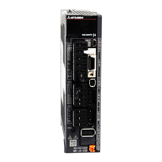
POINT Equipment other than the servo amplifier and servo motor are optional or recommended products. When using an MR-J4-_GF-RJ servo amplifier with the DC power supply input, refer to app. 1 of "MR-J4-_GF_(-RJ) Servo Amplifier Instruction Manual (Motion Mode)". The diagram shows MR-J4-20GF-RJ. - Page 23 4. This is for MR-J4-_GF-RJ servo amplifier. MR-J4-_GF servo amplifier does not have CN2L connector. When using MR-J4- _GF-RJ servo amplifier in the linear servo system or in the fully closed loop system, connect an external encoder to this connector.
-
Page 24: Cc-Link Ie Field Network Basic Protocol
2. CC-Link IE FIELD NETWORK BASIC PROTOCOL 2. CC-Link IE FIELD NETWORK BASIC PROTOCOL 2.1 Summary In CC-Link IE Field Network Basic, a command that a master station (controller) sends to slave stations (servo amplifiers) is called a request message, and a command that the slave stations (servo amplifiers) send back to the master station (controller) is called a response message. -
Page 25: Link Device
2. CC-Link IE FIELD NETWORK BASIC PROTOCOL 2.3 Link device In cyclic communication, communication data of the request message and response message is read as object data (RWwn, RWrn, RYn, and RXn) of the servo amplifier. Table 2.1 and 2.2 list initial settings. Table 2.1 RYn/RXn mapping (pt/idx/jg/hm) Master station →... -
Page 26: Mapping Data Details Of Link Device
2. CC-Link IE FIELD NETWORK BASIC PROTOCOL 2.4 Mapping data details of link device Refer to chapter 10. 2 - 3... - Page 27 2. CC-Link IE FIELD NETWORK BASIC PROTOCOL MEMO 2 - 4...
-
Page 28: Slmp
3. SLMP 3. SLMP 3.1 Summary POINT This servo amplifier does not support SLMP (TCP). When commands are sent from multiple master stations to a servo amplifier at short time intervals, the servo amplifier may fail to receive some of the commands. -
Page 29: Message Format
3. SLMP 3.2 Message format The following shows the request message format to be used when the master station (external device) sends a message, and the response message formats to be used when the slave stations (servo amplifiers) return a message. (1) Request message format SLMP Ethernet... -
Page 30: Command
3. SLMP Item Size Endian Description header This header is for UDP/IP. The header is added on the external device side before being sent. TCP/IP is not supported. Subheader 2 bytes At a request: 5000h (QnA compatible 3E At a response: D000h frame) Subheader 6 bytes... -
Page 31: Cia 402 Read/Write Command
3. SLMP 3.3 Command The following table lists applicable commands. Detailed Name Command Description command explanation CiA 402 object 4020h 0001h Reads data specified by using the CiA 402 object from the servo Section read/write amplifier to the external device. 3.4.1 0002h Writes data specified by using the CiA 402 object from the external... -
Page 32: Sdo Upload (Cia 402 Object Read)
3. SLMP 3.4.1 SDO Upload (CiA 402 object read) When the slave stations (servo amplifiers) receive the CiA 402 object read request from the master station (external device), they return a value of the object corresponding to the specified Index or Sub Index. (1) Request message (command and the following) Number of data Command... -
Page 33: Sdo Object Subid Block Upload (Cia 402 Object Sub Id Continuous Read)
3. SLMP (b) At abnormal completion The response message is the same as that of 3.2 (2) (b). (3) Item list Item Size Endian Description Command 2 bytes Little 4020h Sub command 2 bytes Little 0002h Index 2 bytes Little Specify Index of the object. -
Page 34: Sdo Object Subid Block Download (Cia 402 Object Sub Id Continuous Write)
3. SLMP 3.4.4 SDO Object SubID Block Download (CiA 402 object sub ID continuous write) When the slave stations (servo amplifiers) receive the CiA 402 object sub ID continuous write request from the master station (external device), they write a specified value to the object corresponding to the specified Index or consecutive Sub Index. -
Page 35: Error Codes
3. SLMP 3.5 Error codes The following table lists error codes that are stored in the end code at abnormal completion in SLMP. Error code Cause C059h (1) The sub command is specified incorrectly. (2) A command that is not prescribed is received. C05Ch The request message is incorrect. -
Page 36: Startup
4. STARTUP 4. STARTUP When executing a test run, follow the notice and procedures in this instruction manual. Otherwise, it may cause a malfunction, damage to the machine, or injury. WARNING Do not operate switches with wet hands. Otherwise, it may cause an electric shock. -
Page 37: Switching Power On For The First Time
4. STARTUP 4.1 Switching power on for the first time When switching power on for the first time, follow this section to make a startup. Startup procedure Check whether the servo amplifier and servo motor are wired correctly using Wiring check visual inspection, DO forced output function (section 4.7.1 (d)), etc. -
Page 38: Startup
4. STARTUP 4.2 Startup Confirm that the servo motor operates properly alone before connecting the servo motor with a machine. (1) Slide switch setting To switch to CC-Link IE Field Network Basic communication, turn the slide switch 1 (SW1-1) "OFF (down)"... - Page 39 4. STARTUP Set the IP address by using the SLMP command with the rotary switches (SW2/SW3) on the display of the servo amplifier, MR Configurator2, or a master station (controller). Refer to chapter 7 for IP address parameters and section 4.3.1 for details of the rotary switches. Change the IP address with the rotary switches (SW2/SW3) before powering on the servo amplifier.
- Page 40 4. STARTUP (6) Servo-on Enable the servo-on with the following procedure. (a) Switch on the main and control circuit power supplies. (b) Transmit the servo-on command from the master station (controller). When the servo-on status is enabled, the servo amplifier is ready to operate and the servo motor is locked.
-
Page 41: Switch Setting And Display Of The Servo Amplifier
4. STARTUP 4.3 Switch setting and display of the servo amplifier Switching to CC-Link IE Field Network Basic communication or test operation mode, and setting identification number are enabled with switches on the servo amplifier. On the servo amplifier display (three-digit, seven-segment LED), check the identification number, and diagnose a malfunction at occurrence of an alarm. - Page 42 4. STARTUP (1) Slide switches (SW1-1 and SW1-2) The combination of SW1-1 and SW1-2 enables you to switch communication method and set the test operation mode (enabled/disabled). The following table lists the combinations of the switches. In the test operation mode, the functions such as JOG operation, positioning operation, and machine analyzer are available with MR Configurator2.
-
Page 43: Scrolling Display
4. STARTUP 4.3.2 Scrolling display Axis number will be displayed in hexadecimal. (1) Normal display When there is no alarm, the identification number (2 digits) is displayed. Status Identification No. (1 digit) (2 digits) "b" : Indicates ready-off and servo-off status. "C"... -
Page 44: Status Display
4. STARTUP 4.3.3 Status display (1) Display sequence Servo amplifier power on System check in progress When an alarm No. or warning No. is displayed Example: When [AL. 50 Overload 1] occurs (Note) Ready-off and servo-off at identification No. 1 Blinking Ready-on After 0.8 s... -
Page 45: Ethernet Status Display Led
4. STARTUP (2) Indication list Display Status Description Initializing System check in progress (Note 1) Ready-off The ready-off command was received. (Note 1) Ready-on, servo-off The servo-off command was received. (Note 1) Ready-on, servo-on The servo-on command was received. (Note 1) Alarm occurring An alarm or warning has occurred in the servo amplifier. -
Page 46: Test Operation
4. STARTUP 4.4 Test operation Before starting an actual operation, perform a test operation to make sure that the machine operates normally. Refer to section 4.2 for how to power on and off the servo amplifier. POINT If necessary, verify master station (controller) programs by using motor-less operation. -
Page 47: Test Operation Mode In Mr Configurator2
4. STARTUP 4.5.1 Test operation mode in MR Configurator2 POINT When the test operation mode is selected with the slide switches (SW1-1 and SW1-2), the servo amplifier will not receive commands from the master station (controller). (1) Test operation mode (a) Jog operation Jog operation can be performed without the master station (controller). - Page 48 4. STARTUP (b) Positioning operation Positioning operation can be performed without a master station (controller). Use this operation with the forced stop reset. This operation may be used independently of whether servo-on or servo-off and whether a master station (controller) is connected or not. Perform on the positioning operation screen of MR Configurator2.
- Page 49 4. STARTUP (e) Single-step feed The positioning operation can be performed in accordance with the point table No. set with MR Configurator2. Select the test operation/single-step feed from the menu of MR Configurator2. When the single-step feed window is displayed, input the following items and operate. Point table operation 1) Set the point table No.
-
Page 50: Motor-Less Operation With A Controller
4. STARTUP (2) Operation procedure 1) Turn off the power. 2) Set SW1-1 to "ON (up)" and SW1-2 to "OFF (down)". Set SW1-1 to "ON (up)" and SW1-2 to "OFF (down)". The test operation mode is not enabled when switches SW1-1and SW1-2 are set during power- 3) Turn on the servo amplifier. - Page 51 4. STARTUP (1) Motor-less operation Without a servo motor connected to the servo amplifier, signals are outputted and status is displayed as if the servo motor is actually running in response to the master station. This operation can be used to check the sequence of a master station (controller).
-
Page 52: Network Setting
MR-J4-GF system profile needs to be read into GX Works to set network configuration on GX Works. Obtain the latest system profile (CSP+) from the Mitsubishi Electric FA site (http://www.mitsubishielectric.co.jp/fa/), and register the profile from the Profile Management in the menu. -
Page 53: Cyclic Communication Start
4. STARTUP 4.6.2 Cyclic communication start Start the cyclic communication in the following procedure. [IP address setting] IP address setting The initial value is 192.168.3.0. To change the initial value, set it with any of the following (1) to (3). (Refer to section 4.2 (3).) (1) Rotary switches (SW2/SW3) (2) Parameters ([Pr. -
Page 54: Cia 402 Drive Profile
5. CiA 402 DRIVE PROFILE 5. CiA 402 DRIVE PROFILE POINT Do not give operation commands from two or more master stations to one servo amplifier. Otherwise, the servo motor may operate unexpectedly. This chapter describes how to drive a servo motor in the communication. For MR-J4-_GF_(-RJ) servo amplifier, objects are assigned according to Index of the CiA 402 drive profile. - Page 55 5. CiA 402 DRIVE PROFILE Table 5.1 State transition Transition Event Remark The control circuit power supply is turned on. Initialization The state automatically transitions when the control circuit power Communication setting supply is turned on. The state transitions with the Shutdown command from the master. The state transitions with the Switch on command from the master.
-
Page 56: Related Object
5. CiA 402 DRIVE PROFILE 5.1.2 Related object Data Index Access Name Default Index Type 6040h Controlword 6041h Statusword (1) Controlword (6040h) This object issues a command from the master station (controller) to the slave stations (servo amplifiers). Data Index Access Name Default... - Page 57 5. CiA 402 DRIVE PROFILE (2) Statusword (6041h) Data Index Access Name Default Index Type 6041h Statusword The current control status can be checked. The following table lists the bits of this object. The status can be checked with bit 0 to bit 7. Symbol Description RTSO...
-
Page 58: Directions For Use
5. CiA 402 DRIVE PROFILE Bit 0 to Bit 3, Bit 5, and Bit 6 are switched depending on the state machine (internal state of the MR-J4- _GF_(-RJ) servo amplifier). Refer to the following table for details. Statusword (bin) State machine x0xx xxx0 x0xx 0000 Not ready to switch on (Note) x0xx xxx0 x1xx 0000... -
Page 59: Control Mode
5. CiA 402 DRIVE PROFILE 5.2 Control mode This section describes the control modes of the MR-J4-_GF_(-RJ) servo amplifier. 5.2.1 Function description A control mode of the MR-J4-_GF_(-RJ) servo amplifier can be selected with the control mode (Modes of operation: 6060h). Use [Pr. PA01] to switch the method between the point table method and the indexer method. -
Page 60: Function Description
6. SERVO MOTOR DRIVING 6. SERVO MOTOR DRIVING 6.1 Homing mode (hm) This section describes how to perform a home position return operation in the communication. 6.1.1 Function description For specified home position return operation, set Homing method (6098h), Homing speed (6099h), and Homing acceleration (609Ah), and then start the operation with Controlword (6040h). -
Page 61: Related Object
6. SERVO MOTOR DRIVING 6.1.2 Related object Data Index Access Name Default Description Index Type The home position saved in EEP-ROM is stored at power- on. If a home position return is executed in the homing 607Ch Home offset mode (hm), the home position will be updated. - Page 62 6. SERVO MOTOR DRIVING (1) Controlword (6040h) Data Index Access Name Default Index Type 6040h Controlword The current control command status can be checked. In addition, control commands can be written. The following table lists the bits of this object that relate to the home position return operation. Description 0 to 3 Refer to section 5.1.2.
- Page 63 6. SERVO MOTOR DRIVING The following table lists selectable home position return methods. Rotation Setting value Home position return types Description direction Starting home position return causes "Homing error". Home No homing method assigned position return cannot be executed. Same as the dog type last Z-phase reference home position return.
- Page 64 6. SERVO MOTOR DRIVING Rotation Setting value Home position return types Description direction Homing without index pulse Reverse rotation Same as the dog type front end reference home position return. Although this type is the same as the dog cradle type home position return, the stop position is not on the Z-phase.
- Page 65 6. SERVO MOTOR DRIVING Rotation Setting value Home position return types Description direction Deceleration starts at the front end of the proximity dog. After the rear end is passed, the position specified by the first Z- phase signal, or the position of the first Z-phase signal shifted Forward rotation by the specified home position shift distance is used as the Dog type...
- Page 66 6. SERVO MOTOR DRIVING (3) Homing speed (6099h) Data Index Access Name Default Index Type Number of entries 6099h Homing speed Speed during search for switch 10000 Speed during search for zero 1000 The current home position return speed can be read. At this time, "02h" is returned to Number of entries. The current home position return speed is returned to Speed during search for switch in a unit of r/min or mm/s.
- Page 67 6. SERVO MOTOR DRIVING The current control status can be checked. The following table lists the bits of this object that relate to the home position return operation. Description 0 to 9 Refer to section 5.1.2. Target reached Refer to (a) and the following table for the definition. Refer to section 5.1.2.
-
Page 68: Directions For Use
6. SERVO MOTOR DRIVING 6.1.3 Directions for use POINT To execute a home position return securely, move the servo motor to the opposite stroke end with jog operation (jg) from the master station (controller) or by using other means before starting a home position return. When changing the mode after the home position return completion, set Target position (607Ah) to "0", and change the control mode. - Page 69 6. SERVO MOTOR DRIVING (2) CiA 402-type Homing method (a) Home position return type in CiA 402 type The following shows the CiA 402-type home position return. 1) Method 3 and 4: Homing on positive home switch and index pulse These home position return types use the front end of the proximity dog as reference and set the Z-phase right before and right after the dog as a home position.
- Page 70 6. SERVO MOTOR DRIVING 3) Method 7, 8, 11, 12: Homing on home switch and index pulse These types include the operation at stroke end detection in addition to the operation of Method 3 to Method 6. Thus, the home position is the same as that of Method 3 to Method 6. Method 7 has the operation of the dog type last Z-phase reference home position return.
- Page 71 6. SERVO MOTOR DRIVING 5) Method 33 and 34: Homing on index pulse These home position return types set the Z-phase detected first as a home position. The operation is the same as that of the dogless Z-phase reference home position return except that the creep speed is applied at the start.
- Page 72 6. SERVO MOTOR DRIVING (b) Operation example of the CiA 402-type Homing method The following shows an operation example of the home position return in the CiA 402-type Homing method. 1) Method 3 (Homing on positive home switch and index pulse) and Method 5 (Homing on negative home switch and index pulse) The following figure shows the operation of Homing method 3.
- Page 73 6. SERVO MOTOR DRIVING 2) Method 4 (Homing on positive home switch and index pulse) and Method 6 (Homing on negative home switch and index pulse) The following figure shows the operation of Homing method 4. The operation direction of Homing method 6 is opposite to that of Homing method 4.
- Page 74 6. SERVO MOTOR DRIVING 3) Method 7 and Method 11 (Homing on home switch and index pulse) The following figure shows the operation of Homing method 7. The operation direction of Homing method 11 is opposite to that of Homing method 7. Statusword bit 10 Target reached Statusword bit 12...
- Page 75 6. SERVO MOTOR DRIVING 4) Method 8 and Method 12 (Homing on home switch and index pulse) The following figure shows the operation of Homing method 8. The operation direction of Homing method 12 is opposite to that of Homing method 8. Statusword bit 10 Target reached Statusword bit 12...
- Page 76 6. SERVO MOTOR DRIVING 5) Method 19 and Method 21 (Homing without index pulse) The following figure shows the operation of Homing method 19. The operation direction of Homing method 21 is opposite to that of Homing method 19. Statusword bit 10 Target reached Statusword bit 12 Homing attained...
- Page 77 6. SERVO MOTOR DRIVING 6) Method 20 and Method 22 (Homing without index pulse) The following figure shows the operation of Homing method 20. The operation direction of Homing method 22 is opposite to that of Homing method 20. Statusword bit 10 Target reached Statusword bit 12 Homing attained...
- Page 78 6. SERVO MOTOR DRIVING 7) Method 23 and Method 27 (Homing without index pulse) The following figure shows the operation of Homing method 23. The operation direction of Homing method 27 is opposite to that of Homing method 23. Statusword bit 10 Target reached Statusword bit 12 Homing attained...
- Page 79 6. SERVO MOTOR DRIVING 8) Method 24 and Method 28 (Homing without index pulse) The following figure shows the operation of Homing method 24. The operation direction of Homing method 28 is opposite to that of Homing method 24. Statusword bit 10 Target reached Statusword bit 12 Homing attained...
- Page 80 6. SERVO MOTOR DRIVING 9) Method 33 and Method 34 (Homing on index pulse) The following figure shows the operation of Homing method 34. The operation direction of Homing method 33 is opposite to that of Homing method 34. Statusword bit 10 Target reached Statusword bit 12 Homing attained...
- Page 81 6. SERVO MOTOR DRIVING (3) Operation example of Manufacturer-specific Homing method The following shows an operation example of the Manufacturer-specific home position return. (a) Method -1 and -33 (1) Dog type home position return The following figure shows the operation of Homing method -1. The operation direction of Homing method -33 is opposite to that of Homing method -1.
- Page 82 6. SERVO MOTOR DRIVING a) Length of the proximity dog To generate the Z-phase signal of the servo motor during the detection of DOG (Proximity dog), set the length of the proximity dog that satisfies equations (6.1) and (6.2). ≥ •...
- Page 83 6. SERVO MOTOR DRIVING 2) Torque limit changing dog type home position return The following figure shows the operation of Homing method -1 in the indexer method. The operation direction of Homing method -33 is opposite to that of Homing method -1. Power supply Statusword bit 10 Target reached...
- Page 84 6. SERVO MOTOR DRIVING (b) Method -2 and -34 (Count type home position return) POINT For the count type home position return, after the front end of the proximity dog is detected, the position is shifted by the distance set in the travel distance after proximity dog.
- Page 85 6. SERVO MOTOR DRIVING Home position return direction Proximity dog Stroke end (Note) Forward Home position return start position rotation Servo motor speed 0 r/min Reverse rotation The home position return starts from here. Note. This is not available with the software limit. When the servo motor returns at the stroke end (c) Method -3 1) Data set type home position return...
- Page 86 6. SERVO MOTOR DRIVING (d) Method -4 and -36 (stopper type home position return) POINT Since the workpiece collides with the mechanical stopper, the home position return speed must be low enough. The following figure shows the operation of Homing method -4. The operation direction of Homing method -36 is opposite to that of Homing method -4.
- Page 87 6. SERVO MOTOR DRIVING (e) Method -6 and -38 (dog type rear end reference home position return) POINT This home position return type depends on the timing of reading DOG (Proximity dog) that has detected the rear end of the proximity dog. Therefore, when the creep speed is set to 100 r/min and a home position return is performed, the home position has an error of ±...
- Page 88 6. SERVO MOTOR DRIVING Home position return direction Proximity dog Stroke end (Note) Forward Home position return start position rotation Servo motor speed 0 r/min Reverse rotation The home position return starts from here. Note. This is not available with the software limit. When the servo motor returns at the stroke end 6 - 29...
- Page 89 6. SERVO MOTOR DRIVING (f) Method -7 and -39 (count type front end reference home position return) POINT This home position return type depends on the timing of reading DOG (Proximity dog) that has detected the front end of the proximity dog. Therefore, when the creep speed is set to 100 r/min and a home position return is performed, the home position has an error of ±...
- Page 90 6. SERVO MOTOR DRIVING (g) Method -8 and -40 (dog cradle type home position return) The following figure shows the operation of Homing method -8. The operation direction of Homing method -40 is opposite to that of Homing method -8. Statusword bit 10 Target reached Statusword bit 12...
- Page 91 6. SERVO MOTOR DRIVING (h) Method -9 and -41 (dog type last Z-phase reference home position return) The following figure shows the operation of Homing method -9. The operation direction of Homing method -41 is opposite to that of Homing method -9. Statusword bit 10 Target reached Statusword bit 12...
- Page 92 6. SERVO MOTOR DRIVING (i) Method -10 and -42 (dog type front end reference home position return) The following figure shows the operation of Homing method -10. The operation direction of Homing method -42 is opposite to that of Homing method -10. Statusword bit 10 Target reached Statusword bit 12...
- Page 93 6. SERVO MOTOR DRIVING (j) Method -11 and -43 (dogless Z-phase reference home position return) The following figure shows the operation of Homing method -11. The operation direction of Homing method -43 is opposite to that of Homing method -11. Statusword bit 10 Target reached Statusword bit 12...
-
Page 94: Point Table Mode (Pt)
6. SERVO MOTOR DRIVING 6.2 Point table mode (pt) 6.2.1 Point table mode (pt) In this mode, you can arrange point tables in advance, select any point tables in "Target point table" , and start the operation with "Controlword bit 4 (New set-point)". You can select either absolute value command method or incremental value command method with [Pr. -
Page 95: Automatic Operation Using Point Table
6. SERVO MOTOR DRIVING 6.2.2 Automatic operation using point table (1) Absolute value command method This function is enabled by selecting either absolute position command method or incremental value command method with the auxiliary function of the point table. (a) Point table Set the point table values using MR Configurator2 or "Point table 001 to 255". - Page 96 6. SERVO MOTOR DRIVING (b) Parameter setting Set the following parameters to perform automatic operation. 1) Command method selection ([Pr. PT01]) Select the absolute value command method as shown below. [Pr. PT01] Absolute value command method 2) Rotation direction selection ([Pr. PA14]) Select the servo motor rotation direction when "Controlword bit 4 (New set-point)"...
- Page 97 6. SERVO MOTOR DRIVING (c) Operation Selecting the point table with "Target point table" and switching on "Controlword bit 4 (New set- point)" starts positioning to the position data at the set speed, acceleration time constant and deceleration time constant. Item Object to be used Setting...
- Page 98 6. SERVO MOTOR DRIVING (b) Parameter setting Set the following parameters to perform automatic operation. 1) Command method selection ([Pr. PT01]) Select the incremental value command method as shown below. [Pr. PT01] Incremental value command method 2) Rotation direction selection ([Pr. PA14]) Select the servo motor rotation direction when "Controlword bit 4 (New set-point)"...
-
Page 99: Related Object
6. SERVO MOTOR DRIVING (c) Operation Selecting the point table with "Target point table" and switching on "Controlword bit 4 (New set- point)" starts positioning to the position data at the set speed, acceleration time constant and deceleration time constant. Switching on "Controlword bit 5 (Direction)"... - Page 100 6. SERVO MOTOR DRIVING (1) Related object Data Index Name Access Default Description Type Software position limit Number of entries 607Dh Min position limit Minimum position address (Pos units) Max position limit Maximum position address (Pos units) Deceleration time constant for Quick stop Quick stop 6085h deceleration...
- Page 101 6. SERVO MOTOR DRIVING Data Index Name Access Default Description Type Point table command 0: Not operate 2D60h Target point table 1 to 255: Execute the specified point table -1: High-speed home position return Point table demand The currently specified point table No. is returned.
-
Page 102: Point Table Setting Method With Mr Configurator2
6. SERVO MOTOR DRIVING (3) Details on the OMS bit of Statusword (pt mode) Symbol Description (reserved) The value at reading is undefined. Set-point 0: Positioning completed (wait for next command) acknowledge 1: Positioning being executed 0: No following error 1: Following error Judgment condition for Following error Following error... - Page 103 6. SERVO MOTOR DRIVING (a) Writing point table data (a) Select changed point table data, and click "Selected Items Write" to write the changed point table data to the servo amplifier. (b) Writing all point table data (b) Click "Write All" to write all the point table data to the servo amplifier. (c) Reading all point table data (c) Click "Read"...
- Page 104 6. SERVO MOTOR DRIVING (2) Detailed setting window The position data range and unit can be changed with the detailed setting in the point table window. For the position data range and unit in [Pr. PT01] setting, refer to section 6.2.2. To reflect the setting for the corresponding parameter, click the "Update Project"...
-
Page 105: Point Table Setting Method With Objects
6. SERVO MOTOR DRIVING 6.2.5 Point table setting method with objects To change the point table of the servo amplifier on the master station (controller), write values to the following objects in the SDO communication. However, once the power supply is shut off, the changed setting is not held at the next startup. -
Page 106: Directions For Use
6. SERVO MOTOR DRIVING 6.2.6 Directions for use (1) pt mode operation sequence (a) Automatic individual positioning operation 1) Absolute value command method ([Pr. PT01] = _ _ _ 0) While the servo motor is stopped under servo-on state, switching on "Controlword bit 4 (New set- point)"... - Page 107 6. SERVO MOTOR DRIVING 2) Incremental value command method ([Pr. PT01] = _ _ _ 1) While the servo motor is stopped under servo-on state, selecting a rotation direction with "Controlword bit 5 (Direction)" and switching on "Controlword bit 4 (New set-point)" starts the automatic positioning operation.
- Page 108 6. SERVO MOTOR DRIVING (b) Automatic continuous positioning operation By merely selecting a point table and switching on "Controlword bit 4 (New set-point)", the operation can be performed in accordance with the point tables having consecutive numbers. 1) Absolute value command method ([Pr. PT01] = _ _ _ 0) By specifying the absolute value command or the incremental value command in the auxiliary function of the point table, the automatic continuous operation can be performed.
- Page 109 6. SERVO MOTOR DRIVING b) Positioning in the reverse direction during a series of point-table operation The following shows an operation example with the set values listed in the table below. In this example, point table No. 1 and No. 3 are set to the absolute value command method, and point table No.
- Page 110 6. SERVO MOTOR DRIVING 2) Incremental value command method ([Pr. PT01] = _ _ _ 1) The position data of the incremental value command method is the sum of the position data of consecutive point tables. The following shows how to set. Point table setting Dwell Auxiliary function...
- Page 111 6. SERVO MOTOR DRIVING (c) Varying-speed operation By setting the auxiliary function of the point table, the servo motor speed during positioning can be changed. Point tables are prepared as many as the number of the set speeds. 1) Absolute value command method ([Pr. PT01] = _ _ _ 0) Set "1"...
- Page 112 6. SERVO MOTOR DRIVING a) Positioning in a single direction The following shows an operation example with the set values listed in the table below. In this example, point table No. 1 and No. 3 are set to the absolute value command method, and point table No.
- Page 113 6. SERVO MOTOR DRIVING b) Positioning in the reverse direction during a series of point-table operation The following shows an operation example with the set values listed in the table below. In this example, point table No. 1 and No. 3 are set to the absolute value command method, and point table No.
- Page 114 6. SERVO MOTOR DRIVING 2) Incremental value command method ([Pr. PT01] = _ _ _ 1) Setting "1" to the auxiliary function executes positioning at the speed set in the subsequent point table. At this time, the position data selected at start is enabled, and the acceleration/deceleration time constant set in the next and subsequent point tables is disabled.
- Page 115 6. SERVO MOTOR DRIVING (d) Automatic repeat positioning operation By setting the auxiliary function of the point table, the sequence of operation patterns arranged on the point table can be restarted, enabling repetitive positioning operation. 1) Absolute value command method ([Pr. PT01] = _ _ _ 0) Setting "8"...
- Page 116 6. SERVO MOTOR DRIVING Example 2. Operations when "9" is set to the auxiliary function of point table No. 3 Acceleration Deceleration Point table Position data Servo motor Auxiliary time constant time constant Dwell [ms] μm] speed [r/min] function [ms] [ms] 0.00 3000.00...
- Page 117 6. SERVO MOTOR DRIVING b) Automatic repeat positioning operation by incremental value command method Example 1. Operations when "10" is set to the auxiliary function of point table No. 4 Acceleration Deceleration Point table Position data Servo motor Auxiliary time constant time constant Dwell [ms] μm]...
- Page 118 6. SERVO MOTOR DRIVING Example 2. Operations when "11" is set to the auxiliary function of point table No. 3 Acceleration Deceleration Point table Position data Servo motor Auxiliary time constant time constant Dwell [ms] μm] speed [r/min] function [ms] [ms] 5.00 3000.00...
- Page 119 6. SERVO MOTOR DRIVING c) Varying-speed operation by absolute value command method Example. Operations when "8" is set to the auxiliary function of point table No. 3 Acceleration Deceleration Point table Position data Servo motor Auxiliary time constant time constant Dwell [ms] μm] speed [r/min]...
- Page 120 6. SERVO MOTOR DRIVING d) Varying-speed operation by incremental value command method Example. Operations when "10" is set to the auxiliary function of point table No. 3 Acceleration Deceleration Point table Position data Servo motor Auxiliary time constant time constant Dwell [ms] μm] speed [r/min]...
- Page 121 6. SERVO MOTOR DRIVING 2) Incremental value command method ([Pr. PT01] = _ _ _ 1) Setting "8" to the auxiliary function performs automatic continuous operation or varying-speed operation until that point table, and after the completion of positioning, performs the operation again from the operation pattern of the set point table.
- Page 122 6. SERVO MOTOR DRIVING Example 2. Operations when "9" is set to the auxiliary function of point table No. 2 Acceleration Deceleration Point table Position data Servo motor Auxiliary time constant time constant Dwell [ms] μm] speed [r/min] function [ms] [ms] 5.00 3000.00...
- Page 123 6. SERVO MOTOR DRIVING b) Varying-speed operation by incremental value command method Example. Operations when "8" is set to the auxiliary function of point table No. 2 Acceleration Deceleration Point table Position data Servo motor Auxiliary time constant time constant Dwell [ms] μm] speed [r/min]...
- Page 124 6. SERVO MOTOR DRIVING (e) Temporary stop/restart When "Controlword bit 8 (HALT)" is switched on during automatic operation, the servo motor decelerates with the deceleration time constant of the point table being executed, and then stops temporarily. When "Controlword bit 8 (HALT)" is switched off during a temporary stop, the servo motor starts to travel for the remaining travel distance.
- Page 125 6. SERVO MOTOR DRIVING 2) During dwell Point table No. n Point table No. n + 1 Dwell = ta + tb Forward rotation 0 r/min Servo motor speed Reverse rotation Target point table No. n Controlword bit 4 (New set-point) Controlword bit 8 (Halt) Status DO 5 bit 5 (S_CPO (Rough match))
-
Page 126: Indexer Mode (Idx)
6. SERVO MOTOR DRIVING 6.3 Indexer mode (idx) POINT In the absolute position detection system, rotating the shaft one revolution or more during power-off may erase the home position. Therefore, do not rotate the shaft one revolution or more during power-off. When the home position is erased, [AL. -
Page 127: Rotation Direction Specifying Indexer
6. SERVO MOTOR DRIVING (2) Rotation direction There are two operation methods: Rotation direction specifying indexer, which always rotates in a fixed direction and executes positioning to a station; Shortest rotating indexer, which automatically changes a rotation direction to the shortest distance and executes positioning to a station. Rotation direction specifying indexer Shortest rotating indexer 6.3.2 Rotation direction specifying indexer... - Page 128 6. SERVO MOTOR DRIVING (2) Other parameter settings (a) Setting assignment direction of station No. Select an assignment direction of station No. with [Pr. PA14]. [Pr. PA14] setting Assignment direction of station No. Next station No. will be assigned in CW direction in order of 1, 2, 3…...
- Page 129 6. SERVO MOTOR DRIVING 6.3.3 Shortest rotating indexer This operation mode automatically changes a rotation direction to the shortest distance to execute positioning to a station. Select a station No. with "Target point table" to execute positioning. The values set in the object are used for the servo motor speed, acceleration time constant, and deceleration time constant during operation.
-
Page 130: Related Object
6. SERVO MOTOR DRIVING 6.3.4 Related object The following shows the functions and related objects of the indexer mode (idx). [Pr. PC77] Torque limit Torque limit value (60E0h, 60E1h) × function Control Profile acceleration (6083h) effort (60FAh) Torque Position Velocity Motor control Profile deceleration (6084h) - Page 131 6. SERVO MOTOR DRIVING Data Index Name Access Default Description Type Current speed 606Ch Velocity actual value Unit: Vel unit (0.01 r/min) Current torque 6077h Torque actual value Unit: 0.1% (rated torque of 100%) Travel distance per revolution of an output shaft Feed constant Refer to chapter 10.
- Page 132 6. SERVO MOTOR DRIVING (2) Details on the OMS bit of Controlword (idx mode) Symbol Description The operation starts toward the point table specified with the Target point table (2D60h) New set-point when the bit turns on. 0: Station No. decreasing direction Direction 1: Station No.
-
Page 133: Directions For Use
6. SERVO MOTOR DRIVING 6.3.5 Directions for use (1) idx mode operation sequence (a) Rotation direction specifying indexer POINT Be sure to perform a home position return. Executing positioning operation without home position return will trigger [AL. 90 Home position return incomplete warning] and "Controlword bit 4 (New set-point)"... - Page 134 6. SERVO MOTOR DRIVING Note 1. When the specified station No. exceeds the value set in [Pr. PT28 Number of stations per rotation] -1, the servo motor does not operate. 2. "Controlword bit 4 (New set-point)" is not received when the remaining command travel distance is other than "0". 3.
- Page 135 6. SERVO MOTOR DRIVING 2) When using Target speed No. (2DD1h) For the servo motor speed, acceleration time constant and deceleration time constant during operation, the values set in the point table are used. Set the point table No. to be used in Target speed No.
- Page 136 6. SERVO MOTOR DRIVING Note 1. When the specified station No. exceeds the value set in [Pr. PT28 Number of stations per rotation] -1, the servo motor does not operate. 2. "Controlword bit 4 (New set-point)" is not received when the remaining command travel distance is other than "0". 3.
- Page 137 6. SERVO MOTOR DRIVING (b) Shortest rotating indexer POINT Be sure to perform a home position return. Executing positioning operation without home position return will trigger [AL. 90 Home position return incomplete warning] and "Controlword bit 4 (New set-point)" will be disabled. When travel distances to a target station position from CCW and from CW are the same, the shaft will rotate to the increasing direction of the station No.
- Page 138 6. SERVO MOTOR DRIVING Note 1. When the specified station No. exceeds the value set in [Pr. PT28 Number of stations per rotation] -1, the servo motor does not operate. 2. "Controlword bit 4 (New set-point)" is not received when the remaining command travel distance is other than "0". 3.
- Page 139 6. SERVO MOTOR DRIVING 2) When using Target speed No. (2DD1h) For the servo motor speed, acceleration time constant and deceleration time constant during operation, the values set in the point table are used. Set the point table No. to be used in Target speed No.
- Page 140 6. SERVO MOTOR DRIVING Note 1. When the specified station No. exceeds the value set in [Pr. PT28 Number of stations per rotation] -1, the servo motor does not operate. 2. "Controlword bit 4 (New set-point)" is not received when the remaining command travel distance is other than "0". 3.
-
Page 141: Jog Mode (Jg)
6. SERVO MOTOR DRIVING 6.4 Jog mode (jg) 6.4.1 Function description For the machine adjustment, home position adjustment, and others, positioning to any point is possible with the jog mode (jg). Jog operation is available in the point table method, and station jog operation and jog operation are available in the indexer method. - Page 142 6. SERVO MOTOR DRIVING (2) Station jog operation in the indexer method (a) Setting Set objects and parameters as shown below depending on the intended application. In this operation, "Target point table" is disabled. Item Object/parameter to be used Setting Jog mode (jg) selection Modes of operation Set "-100".
- Page 143 6. SERVO MOTOR DRIVING (c) Operation Switching on "Controlword bit 4 (Rotation start)" starts rotation to a direction specified with "Controlword bit 5 (Direction)", and switching off "Controlword bit 4 (Rotation start)" executes a positioning to the closest station position where the servo motor can decelerate to a stop. Note that the speed may not reach the specified speed because the shaft stops with the set time constant, depending on the setting value of deceleration time constant.
-
Page 144: Related Object
6. SERVO MOTOR DRIVING 6.4.2 Related object The following shows the function and related objects of the jog mode (jg). [Pr. PC77] Torque limit Torque limit value (60E0h, 60E1h) × function Software position limit (607Dh) × Control Profile acceleration (6083h) effort (60FAh) Torque... - Page 145 6. SERVO MOTOR DRIVING Data Index Name Access Default Description Type Deceleration time constant for Quick stop Quick stop 6085h deceleration Unit: ms Operation setting for Quick stop Quick stop option 605Ah code Refer to chapter 10. Position actual 6063h Current position (Enc inc) internal value Current position (Pos units)
- Page 146 6. SERVO MOTOR DRIVING (2) Details on the OMS bit of Controlword (jg mode) Symbol Description 0: Stop the servo motor Rotation start 1: Start the servo motor 0: Forward rotation (address increase) Direction 1: Reverse rotation (address decrease) (reserved) The value at reading is undefined.
- Page 147 6. SERVO MOTOR DRIVING (4) jg mode operation sequence in the point table method (a) When operating at a constant speed Decelerates with Profile deceleration Forward rotation Servo motor speed 0 r/min Reverse rotation Accelerates with Profile acceleration Controlword bit 4 (Rotation start) Controlword bit 5 (Direction)
- Page 148 6. SERVO MOTOR DRIVING (5) jg mode operation sequence in the indexer method (a) Station jog operation The following timing chart shows that a jog operation is started from being stopped at the station No. 0 at servo-on. (Note 1) Controlword bit 4 (Rotation start) Controlword bit 5...
- Page 149 6. SERVO MOTOR DRIVING (b) Jog operation The following timing chart shows that a jog operation is started from being stopped at the station No. 0 at servo-on. Controlword bit 4 (Rotation start) Controlword bit 5 (Direction) Profile velocity 100.00 r/min 150.00 r/min Forward rotation...
-
Page 150: Parameters
7. PARAMETERS 7. PARAMETERS Never make a drastic adjustment or change to the parameter values as doing so will make the operation unstable. Do not change the parameter settings as described below. Doing so may cause an unexpected condition, such as failing to start up the servo amplifier. Changing the values of the parameters for manufacturer setting CAUTION Setting a value out of the range... - Page 151 7. PARAMETERS 7.1.1 Basic setting parameters ([Pr. PA_ _ ]) Initial Detailed Symbol Name Unit value explanation PA01 **STY Operation mode 1000h Section 7.2.1 PA02 **REG Regenerative option 0000h Motion mode PA03 *ABS Absolute position detection system 0000h PA04 *AOP1 Function selection A-1 2000h PA05...
- Page 152 7. PARAMETERS 7.1.2 Gain/filter setting parameters ([Pr. PB_ _ ]) Initial Detailed Symbol Name Unit value explanation PB01 FILT Adaptive tuning mode (adaptive filter II) 0000h Motion mode PB02 VRFT Vibration suppression control tuning mode (advanced vibration 0000h suppression control II) PB03 For manufacturer setting 18000...
- Page 153 7. PARAMETERS Initial Detailed Symbol Name Unit value explanation PB47 NHQ3 Notch shape selection 3 0000h Motion mode PB48 Machine resonance suppression filter 4 4500 [Hz] PB49 NHQ4 Notch shape selection 4 0000h PB50 Machine resonance suppression filter 5 4500 [Hz] PB51 NHQ5...
- Page 154 7. PARAMETERS 7.1.3 Extension setting parameters ([Pr. PC_ _ ]) Initial Detailed Symbol Name Unit value explanation PC01 Error excessive alarm level [rev]/[mm] Motion mode PC02 Electromagnetic brake sequence output [ms] PC03 *ENRS Encoder output pulse selection 0000h PC04 **COP1 Function selection C-1 0000h PC05...
- Page 155 7. PARAMETERS Initial Detailed Symbol Name Unit value explanation PC51 For manufacturer setting 0000h PC52 0000h PC53 0000h PC54 0000h PC55 0000h PC56 0000h PC57 0000h PC58 0000h PC59 0000h PC60 0000h PC61 0000h PC62 0000h PC63 0000h PC64 0000h PC65 50.00 PC66...
- Page 156 7. PARAMETERS 7.1.4 I/O setting parameters ([Pr. PD_ _ ]) Initial Detailed Symbol Name Unit value explanation PD01 *DIA1 Input signal automatic on selection 1 0000h Motion mode PD02 For manufacturer setting 0000h PD03 *DI1 Input device selection 1 000Ah Motion mode PD04...
- Page 157 7. PARAMETERS 7.1.5 Extension setting 2 parameters ([Pr. PE_ _ ]) Initial Detailed Symbol Name Unit value explanation PE01 **FCT1 Fully closed loop function selection 1 0000h Motion mode PE02 For manufacturer setting 0000h PE03 *FCT2 Fully closed loop function selection 2 0003h Motion mode...
- Page 158 7. PARAMETERS Initial Detailed Symbol Name Unit value explanation PE48 *LMOP Lost motion compensation function selection 0000h Motion mode PE49 LMCD Lost motion compensation timing [0.1 ms] PE50 LMCT Lost motion compensation non-sensitive band [pulse]/ [kpulse] PE51 For manufacturer setting 0000h PE52 0000h...
- Page 159 7. PARAMETERS Initial Detailed Symbol Name Unit value explanation PF31 FRIC Machine diagnosis function - Friction judgment speed [r/min]/[mm/s] Motion mode PF32 For manufacturer setting PF33 0000h PF34 *MFP Machine diagnosis function selection 0000h Motion mode PF35 For manufacturer setting 0000h PF36 0000h...
- Page 160 7. PARAMETERS 7.1.7 Linear servo motor/DD motor setting parameters ([Pr. PL_ _ ]) Initial Detailed Symbol Name Unit value explanation PL01 **LIT1 Linear servo motor/DD motor function selection 1 0301h Motion mode PL02 **LIM Linear encoder resolution - Numerator 1000 [µm] PL03 **LID...
- Page 161 7. PARAMETERS 7.1.8 Positioning control parameters ([Pr. PT_ _ ]) Initial Detailed Symbol Name Unit value explanation PT01 **CTY Command mode selection 0300h Section 7.2.4 PT02 For manufacturer setting 0001h PT03 *FTY Feeding function selection 0000h Section 7.2.4 PT04 For manufacturer setting 0000h PT05 Home position return speed...
- Page 162 7. PARAMETERS Initial Detailed Symbol Name Unit value explanation PT41 Home position return inhibit function selection 0000h Motion mode PT42 For manufacturer setting PT43 PT44 0000h PT45 Home position return types Motion mode PT46 For manufacturer setting 0000h PT47 0000h PT48 0000h PT49...
- Page 163 7. PARAMETERS 7.1.9 Network setting parameters ([Pr. PN_ _ ]) Initial Detailed Symbol Name Unit value explanation PN01 For manufacturer setting PN02 CERT Communication error detection time [ms] Section 7.2.5 PN03 **NWMD Communication mode setting for CC-Link IE communication 0000h PN04 **NWNO CC-Link IE communication network number...
-
Page 164: Basic Setting Parameters ([Pr. Pa
7. PARAMETERS 7.2 Detailed list of parameters POINT For parameters which are not described in this section, refer to chapter 5 of "MR-J4-_GF_(-RJ) Servo Amplifier Instruction Manual (Motion Mode)". Set a value to each "x" in the "Setting digit" columns. The symbols in the control mode column mean as follows: CP: Point table method PS: Indexer method... - Page 165 7. PARAMETERS Control Initial mode No./symbol/ Setting Function value digit name [unit] PA06 Set the number of gear teeth on machine side. (Refer to section 7.2.6.) *CMX Set the electronic gear within the following range. Setting out of the range will trigger [AL. 37 Parameter error].
- Page 166 7. PARAMETERS 7.2.2 Extension setting parameters ([Pr. PC_ _ ]) Control Initial mode No./symbol/ Setting Function value digit name [unit] PC77 The parameter is for limiting the torque of the servo motor. Set this on the assumption that the rated torque is 100.0 %. When this parameter is set to "0.0", torque is not generated.
-
Page 167: Positioning Control Parameters ([Pr. Pt
7. PARAMETERS 7.2.4 Positioning control parameters ([Pr. PT_ _ ]) Control Initial mode No./symbol/ Setting Function value digit name [unit] PT01 _ _ _ x Positioning command method selection **CTY 0: Absolute value command method Command 1: Incremental value command method mode _ _ x _ For manufacturer setting selection... - Page 168 7. PARAMETERS Control Initial mode No./symbol/ Setting Function value name digit [unit] PT15 Set an address increasing side of the software stroke limit. 0000h Refer to LMPL The combination of the upper and lower digits makes one address. Function Software limit Set an address in hexadecimal.
- Page 169 7. PARAMETERS Control Initial mode No./symbol/ Setting Function value name digit [unit] PT21 Set an address decreasing side of the position range output address. 0000h The combination of the upper and lower digits makes one address. Using [Pr. PT19] to Refer to *LNPL [Pr.
- Page 170 7. PARAMETERS Control Initial mode No./symbol/ Setting Function value name digit [unit] PT35 _ _ _ x For manufacturer setting *TOP5 _ _ x _ Function _ x _ _ Simple cam function selection selection T-5 0: Disabled 1: Enabled (cam position compensation disabled) 2: Enabled (cam position compensation enabled by touch probe 1 (TPR1)) 3: Enabled (cam position compensation enabled by touch probe 2 (TPR2)) Simple cam function is enabled when the control mode is in the point table method.
- Page 171 7. PARAMETERS Control Initial mode No./symbol/ Setting Function value name digit [unit] PT45 Set a home position return type. Refer to the following table for details. Home Setting a value other than the setting values in the following tables (other than "-1", "-3", position "-33", "35", and "37"...
- Page 172 7. PARAMETERS Control Initial mode No./symbol/ Setting Function value name digit [unit] PT45 Setting Home position Home position Setting Home position Home position Home value return direction return method value return direction return method position Address Method 3 Address Method 21 return types increasing decreasing...
- Page 173 7. PARAMETERS Control Initial mode No./symbol/ Setting Function value name digit [unit] PT49 Set the acceleration time taken from 0 r/min (0 mm/s) to the rated speed for the command. [ms] If the servo motor is started with a value exceeding 20000 ms, [AL. F4] will occur, and the Acceleration servo motor will not operate.
- Page 174 7. PARAMETERS Control Initial mode No./symbol/ Setting Function value name digit [unit] PT51 This parameter is used to smooth start/stop of the servo motor or linear servo motor. [ms] Set the time of the arc part for S-pattern acceleration/deceleration. S-pattern Setting "0"...
- Page 175 7. PARAMETERS Control Initial mode No./symbol/ Setting Function value name digit [unit] PT69 Set the extension parameter of [Pr. PT07]. Refer to ZSTH When [Pr. PT69] is used, the home position shift distance is calculated as follows. Function Home Home position shift distance = [Pr. PT07] + ([Pr. PT69] × 65536) column position shift The unit will be as follows depending on the positioning mode.
-
Page 176: Network Setting Parameters ([Pr. Pn
7. PARAMETERS 7.2.5 Network setting parameters ([Pr. PN_ _ ]) Control Initial mode No./symbol/ Setting Function value digit name [unit] PN02 Set the time until [AL. 86.1 Network communication error 1] is detected. [ms] CERT When "0" is set, the detection time becomes 1000 [ms]. Communicati on error Setting range: 0 to 1000... - Page 177 7. PARAMETERS Control Initial mode No./symbol/ Setting Function value name digit [unit] PN12 _ _ x x IP address setting 4 **IPADB Set the 4th octet of the IP address in hexadecimal. IP address Set the IP address assigned by the network administrator. setting B When SLMP command (IPAddressSet) is received, the setting of the 4th octet will be written to this digit.
- Page 178 7. PARAMETERS Control Initial mode No./symbol/ Setting Function value name digit [unit] PN18 _ _ x x IP address filter 2 **IPAFA Set the 2nd octet of the IP address of the network device allowed to be connected in hexadecimal. IP address filter A When both [Pr.
- Page 179 7. PARAMETERS Control Initial mode No./symbol/ Setting Function value name digit [unit] PN22 _ _ x x Operation specification IP address 2 **IPOAA Set the 2nd octet of the IP address of the network device allowed to be connected in hexadecimal.
- Page 180 7. PARAMETERS Control Initial mode No./symbol/ Setting Function value name digit [unit] PN24 _ _ x x Operation specification IP address 4 range specification **IPOR Set a value for the 4th octet range of the IP address of the network device allowed to be connected in hexadecimal.
-
Page 181: How To Set The Electronic Gear
7. PARAMETERS 7.2.6 How to set the electronic gear (1) Electronic gear settings in the point table method Adjust [Pr. PA06] and [Pr. PA07] to match the servo amplifier setting with the travel distance of the machine. Electronic gear ([Pr. PA06] [Pr. PA07]) Servo motor Travel distance Deviation counter... - Page 182 7. PARAMETERS (b) Setting example of a conveyor r = 160 [mm] Machine specifications Pulley diameter: r = 160 [mm] Servo motor encoder resolution Reduction ratio: 1/n = Z = 1/3 4194304 [pulse/rev] : Number of gear teeth on servo motor side 1/n = Z = 1/3 : Number of gear teeth on load side...
-
Page 183: Stop Method At Software Limit Detection
7. PARAMETERS 7.2.7 Stop method at software limit detection By setting the third digit in [Pr. PD12], select a stop method of the servo motor for when a software limit ([Pr. PT15] to [Pr. PT18]) is detected. With the software limit, a command position controlled in the servo amplifier is limited. -
Page 184: Troubleshooting At Power On
8. TROUBLESHOOTING AT POWER ON 8. TROUBLESHOOTING AT POWER ON To remove the cause of the troubles, refer to the troubleshooting at power on described in this chapter and in "MELSERVO-J4 Servo Amplifier Instruction Manual (Troubleshooting)". Display Description Cause Checkpoint Action b##. - Page 185 8. TROUBLESHOOTING AT POWER ON MEMO 8 - 2...
-
Page 186: Manufacturer Functions
9. MANUFACTURER FUNCTIONS 9. MANUFACTURER FUNCTIONS 9.1 Stroke end When LSP (Forward rotation stroke end) or LSN (Reverse rotation stroke end) is turned off, a slow stop is performed by either of the following stop methods. Operation status Remark During rotation at constant speed During deceleration to a stop The servo motor stops after No S-pattern acceleration/... -
Page 187: One-Touch Tuning
9. MANUFACTURER FUNCTIONS 9.2 One-touch tuning For one-touch tuning, refer to "MR-J4-_GF_(-RJ) Servo Amplifier Instruction Manual (Motion Mode)". Using One-touch tuning mode (2D50h) allows one-touch tuning from the master station (controller). (1) Related object Data Index Access Name Default Description Type Setting "1"... - Page 188 9. MANUFACTURER FUNCTIONS (2) Procedure of one-touch tuning via a network Perform one-touch tuning via a network in the following procedure. Start Refer to "MR-J4-_GF_(-RJ) Servo Amplifier Instruction Manual (Motion Startup of the system Mode)" to start the system. Rotate the servo motor by a master station (controller). (One-touch tuning Operation cannot be executed if the servo motor is not operating.) To perform one-touch tuning, write a value of the response mode (high mode,...
-
Page 189: Machine Diagnosis Function
9. MANUFACTURER FUNCTIONS 9.3 Machine diagnosis function From the data in the servo amplifier, this function estimates the friction and vibrational component of the drive system in the equipment, and recognizes an error in the machine parts, including a ball screw and bearing. -
Page 190: Simple Cam Function
9. MANUFACTURER FUNCTIONS 9.5 Simple cam function The number of write times to the Flash-ROM where the cam data is stored is CAUTION limited to 10000. If the total number of write times exceeds 10000, the servo amplifier may malfunction when the Flash-ROM reaches the end of its useful life. POINT The simple cam function can be used with the point table method. -
Page 191: Simple Cam Function Block Diagram
9. MANUFACTURER FUNCTIONS 9.5.2 Simple cam function block diagram The following shows the function block diagram of the simple cam. Use MR Configurator2 to set the cam data and the cam control data. Main shaft Clutch input axis control command selection command Synchronous... -
Page 192: Simple Cam Specification List
9. MANUFACTURER FUNCTIONS 9.5.3 Simple cam specification list (1) Specification list Item MR-J4-_GF_-RJ Storage area for 8 Kbytes (Flash-ROM) cam data Memory capacity (Note) Working area for 8 Kbytes (RAM) cam data Number of registration Max. 8 Max. 32 single-byte characters for each cam data and Comment cam control data Cam resolution... -
Page 193: Control Of Simple Cam Function
9. MANUFACTURER FUNCTIONS 9.5.4 Control of simple cam function Setting the cam data and the cam control data with MR Configurator2 enables the following three cam controls. control Description Actual motion method Cam data and cam control data Cam axis one cycle current value (Input) Reciprocates... -
Page 194: Operation In Combination With The Simple Cam
9. MANUFACTURER FUNCTIONS 9.5.5 Operation in combination with the simple cam (1) Encoder following function The servo amplifier receives A/B-phase output signal from a synchronous encoder and starts the servo motor with the signal. Up to 4 Mpulses/s can be inputted from the synchronous encoder to use with the servo amplifier. MR-J4-GF-RJ servo amplifier A/B-phase output... -
Page 195: Setting List
9. MANUFACTURER FUNCTIONS 9.5.6 Setting list (1) List of items set with MR Configurator2 Set the following on the cam setting window of MR Configurator2. Setting item Setting Select a command input method for the cam axis. Main shaft input axis selection Select "synchronous encoder axis"... -
Page 196: Data To Be Used With Simple Cam Function
9. MANUFACTURER FUNCTIONS 9.5.7 Data to be used with simple cam function The number of write times to the Flash-ROM where the cam control data and cam data are stored is limited to 10000. If the total number of write times exceeds CAUTION 10000, the servo amplifier may malfunction when the Flash-ROM reaches the end of its useful life. - Page 197 9. MANUFACTURER FUNCTIONS (2) Cam data POINT If the cam data is set incorrectly, the position command and speed command may increase and may cause machine interference or [AL. 31 Overspeed]. When you have created and changed cam data, make sure to perform test operations and make appropriate adjustments.
- Page 198 9. MANUFACTURER FUNCTIONS 1) Feed current value The feed current value of the cam axis is calculated as follows: Feed current value = Cam standard position + (Cam stroke amount × Stroke ratio to cam axis current value per cycle) When the cam axis current value per cycle is in the middle of the specified stroke ratio data, the intermediate value is calculated from the cam data before and after the value.
- Page 199 9. MANUFACTURER FUNCTIONS 3) Cam data start position This setting is available only for the stroke ratio data type cam data. The cam data position where the "cam axis current value per cycle" becomes "0" can be set as the cam data start position. The initial value of the cam data start position is "0".
- Page 200 9. MANUFACTURER FUNCTIONS (b) Coordinate data type The following are set in the coordinate data type. Set these in the cam setting window of MR Configurator2. When "Cam No." is set to "0", straight-line control is performed so that the stroke ratio at the last point of the cam data becomes 100%.
- Page 201 9. MANUFACTURER FUNCTIONS 1) Feed current value The feed current value of the cam axis is calculated as follows: Feed current value = Cam standard position + Output value to cam axis current value per cycle When the cam axis current value per cycle is in the middle of the specified stroke ratio data, the intermediate value is calculated from the cam data before and after the value.
- Page 202 9. MANUFACTURER FUNCTIONS 3) Cam data start position This is not used in the coordinate data type. 4) Timing of applying cam control data New values are applied to "Cam No." when bit 5 of Control DI2 (2D02h) turns on. "Cam standard position"...
- Page 203 9. MANUFACTURER FUNCTIONS Control Operation mode mode Initial Symbol Name Unit value For manufacturer setting *MAX Main shaft input axis selection For manufacturer setting MMIX Main shaft input method 0000h For manufacturer setting CLTMD Main shaft clutch control setting 0000h For manufacturer setting CLTSMM Main shaft clutch smoothing system...
- Page 204 9. MANUFACTURER FUNCTIONS Control Operation mode mode Initial Symbol Name Unit value CPHV Cam position compensation target position [µm]/ [inch]/ [degree]/ [pulse] CPHT Cam position compensation time constant [ms] Note. The data is updated at cam control switching. (4) Detailed list of cam control data Control Initial No./symbol/...
- Page 205 9. MANUFACTURER FUNCTIONS Control Initial No./symbol/ Setting mode Function value digit name [unit] pt idx This is enabled when [Cam control data No. 3] is set to "1". Set the initial value of the cam standard position in the output axis position unit. *CIBSS Refer to The unit will be changed to [µm], 10...
- Page 206 9. MANUFACTURER FUNCTIONS Control Initial No./symbol/ Setting mode Function value digit name [unit] pt idx Set a numerator used to convert encoder pulses of the synchronous encoder axis into the synchronous encoder axis unit. *ECMX Set the numerator within the following range. Synchronous encoder axis unit...
- Page 207 9. MANUFACTURER FUNCTIONS Control Initial No./symbol/ Setting mode Function value digit name [unit] pt idx Set an input amount required per cam cycle. *CCYL When [Cam control data No. 30] is set to "0" or "1" Refer to The unit will be changed to [μm], 10 [inch], or [pulse] with the setting of [Pr.
- Page 208 9. MANUFACTURER FUNCTIONS (a) Relation among the main shaft input axis, position data unit, and feed length multiplication setting The parameters used to set the position data unit and feed length multiplication differ depending on the setting of [Cam control data No. 30 Main shaft input axis selection]. Main shaft input axis selection ([Cam control data No.
-
Page 209: Function Block Diagram For Displaying State Of Simple Cam Control
9. MANUFACTURER FUNCTIONS 9.5.8 Function block diagram for displaying state of simple cam control Main axis current value Load-side encoder Under cam control Main axis one cycle current information value Main shaft Clutch input axis control command selection command Synchronous Encoder pulse count Main shaft Main shaft clutch... -
Page 210: Operation
9. MANUFACTURER FUNCTIONS 9.5.9 Operation POINT When using simple cam function, execute operation so that the machine speed of the input axis is equal to or less than "[Cam control data No. 48 - Cam axis length per cycle] × 1/2 × 1000 [command unit/s]". When [Cam control data No. 30] is set to "1", the unit of the cam axis length per cycle will be changed to [mm], [inch], or [pulse] with the setting of [Pr. - Page 211 9. MANUFACTURER FUNCTIONS (2) Setting example When the sheet length is 200.0 mm, the circumferential length of the rotary knife axis (synchronous axis length) is 600.0 mm, and the sheet synchronous width is 10.0 mm, set the following items as follows. Home position Basic settings required to use the simple cam 0°...
- Page 212 9. MANUFACTURER FUNCTIONS (3) Operation The following shows an example of the procedure before operation. Step Setting and operation 1. Data setting Set this referring to (2) in this section. 2. Initial position adjustment Adjust the synchronous positions of the conveyor axis and rotary knife axis. Adjust the machine so that the position of the rotary knife axis (feed current value) is "0"...
- Page 213 9. MANUFACTURER FUNCTIONS (4) Compensation by touch probe This system detects registration marks printed on the sheet in equal intervals, and compensates the difference between the actual cam axis current value per cycle and the ideal cam axis current value per cycle (set value of the cam position compensation target position) by shifting the synchronous phase of the rotary knife axis and the conveyor axis.
- Page 214 9. MANUFACTURER FUNCTIONS (5) Details of cam position compensation This function compensates the difference between the target and actual sensor detection positions by shifting the cam axis current value per cycle. The cam axis length per cycle (sheet length) after compensation (ccyl') is calculated as follows: CCYL: Cam axis length per cycle ([Cam control data No.
-
Page 215: Cam No. Setting Method
9. MANUFACTURER FUNCTIONS 9.5.10 Cam No. setting method POINT When the cam No. is set to a value other than "0" to "8", [AL. F6.5 Cam No. external error] occurs. If the cam data of a specified cam No. does not exist, [AL. F6.3 Cam unregistered error] occurs. - Page 216 9. MANUFACTURER FUNCTIONS (1) Instantaneous stop The operation stops without deceleration. The servo amplifier immediately stops the command. Cam axis one cycle current value Feed current value Feed speed Instantaneous stop (2) Deceleration stop The output axis decelerates to stop according to [Pr. PC51 Forced stop deceleration time constant]. After a deceleration stop starts, the cam axis current value per cycle and feed current value are not updated.
-
Page 217: Restart Operation Of Cam Control
9. MANUFACTURER FUNCTIONS 9.5.12 Restart operation of cam control When the cam control is stopped during operation, a gap may be generated in the synchronous position relationship between the main shaft and the driven shaft. To solve the gap, return the main shaft and the driven shaft to the synchronization starting point and then start the synchronous operation. -
Page 218: Cam Axis Position At Cam Control Switching
9. MANUFACTURER FUNCTIONS 9.5.13 Cam axis position at cam control switching The cam axis position is determined by the positional relationship of three values of "Cam axis current value per cycle", "Cam axis standard position", and "Cam axis feed current value". When the control has been switched to the cam control (bit 5 of Control DI2 (2D02h) is on), defining the positions of two of these values restores the position of the remaining one value. - Page 219 9. MANUFACTURER FUNCTIONS (1) Cam axis one cycle current value restoration POINT For the cam pattern of to-and-fro control, if no corresponding cam axis current value per cycle is found, [AL. F6.1 Cam axis one cycle current value restoration failed] will occur and cam control cannot be executed. For the cam pattern of feed control, if no corresponding cam axis current value per cycle is found, the cam standard position will automatically change and the value will be searched again.
- Page 220 9. MANUFACTURER FUNCTIONS (a) Cam pattern of to-and-fro control 1) Searching from "Cam axis current value per cycle = 0" (Cam data start position = 0) Cam axis one cycle current value Search from "Cam axis one cycle current value = 0". Cam axis feed current value (Feed current value) The cam axis one cycle current value is restored with...
- Page 221 9. MANUFACTURER FUNCTIONS 4) Searching fails Cam axis one cycle current value Cam axis feed current value (Feed current value) When no feed current value that matched is found within one cycle, the restoration fails. Cam standard position (b) Cam pattern of feed control 1) Searching from "Cam axis current value per cycle = 0"...
- Page 222 9. MANUFACTURER FUNCTIONS 3) Searching from a value in the middle of the cam axis current value per cycle (Cam data start position ≠ 0) Cam axis one cycle current value (Initial setting) Cam axis one cycle current value Search from a value in the Cam axis feed current value middle of the cam axis one (Feed current value)
- Page 223 9. MANUFACTURER FUNCTIONS (2) Cam standard position restoration When the cam axis position restoration target is set to "Cam standard position restoration", and then bit 5 of Control DI2 (2D02h) turns on, the control is switched to the cam control, restoring the "Cam standard position"...
- Page 224 9. MANUFACTURER FUNCTIONS (3) Cam axis feed current value restoration POINT When the restored cam axis feed current value differs from the feed current value at cam control switching, the cam axis feed current value moves to the value restored just after the cam control switching. If the difference between the restored cam axis feed current value and the feed current value is larger than the value set in [Pr.
-
Page 225: Clutch
9. MANUFACTURER FUNCTIONS 9.5.14 Clutch Use the clutch when starting or stopping the servo motor by transmitting or shutting commands from the main shaft to the output axis module side with the clutch on/off. Set whether or not to use the clutch control with [Cam control data No. 36 - Main shaft clutch control setting]. Although the clutch ON/OFF can be changed during cam control, the setting of [Cam control data No. -
Page 226: Cam Position Compensation Target Position
9. MANUFACTURER FUNCTIONS 9.5.15 Cam position compensation target position Perform compensation to match the cam axis current value per cycle with the cam position compensation target position ([Cam control parameter No. 60]) by inputting a cam position compensation request. Control DI 2 bit 13 Cam position compensation target position Cam axis one cycle... - Page 227 9. MANUFACTURER FUNCTIONS MEMO 9 - 42...
-
Page 228: Object Dictionary
10. OBJECT DICTIONARY 10. OBJECT DICTIONARY Each data such as control parameters, command values, and feedback values is handled as an object composed of an address, object name, data type, access rule, and other elements. The object data can be exchanged between the master station (controller) and the slave stations (servo amplifiers). - Page 229 10. OBJECT DICTIONARY Data Variable EEP- Param Index Name and function Access Default Range Units Index Type mapping eter 2001 PA01 to PA32 PA01 Impossible The values of the basic setting parameters ([Pr. 2020 PA32 PA_ _ ]) can be obtained and set. Refer to chapter 7 for details.
- Page 230 10. OBJECT DICTIONARY Data Variable EEP- Param Index Name and function Access Default Range Units Index Type mapping eter 2801 Point table 001 to Point table 255 Possible 07h (fixed) Point table 28FF Point data Possible FFF0BDC1h units Unit: pos units 000F423Fh Speed Possible...
- Page 231 10. OBJECT DICTIONARY Data Variable EEP- Param Index Name and function Access Default Range Units Index Type mapping eter 2A40 Clear alarm history Impossible Writing "1EA5h" clears the alarm history. 2A41 Current alarm Possible 00000000h to The number of the current alarm is returned. FFFFFFFFh When no alarm has occurred, "00000000h"...
- Page 232 10. OBJECT DICTIONARY Data Variable EEP- Param Index Name and function Access Default Range Units Index Type mapping eter 2A46 Reset alarm 0000h to Impossible FFFFh Writing the value "1EA5h" resets an alarm. Any value other than "1EA5h" is invalid. 2B01 Cumulative feedback pulses Possible...
- Page 233 10. OBJECT DICTIONARY Data Variable EEP- Param Index Name and function Access Default Range Units Index Type mapping eter 2B2E Unit total power consumption Possible 80000000h to 7FFFFFFFh The unit total power consumption is returned. 2B2F Current position Possible 80000000h to 7FFFFFFFh units The current position is returned.
- Page 234 10. OBJECT DICTIONARY Data Variable EEP- Param Index Name and function Access Default Range Units Index Type mapping eter 2B93 Alarm Monitor 19 Load-side encoder information 2 Possible 80000000h to pulse 7FFFFFFFh The load-side encoder information 2 at alarm occurrence is returned. 2B97 Alarm Monitor 23 Temperature of motor thermistor Possible...
- Page 235 10. OBJECT DICTIONARY Data Variable EEP- Param Index Name and function Access Default Range Units Index Type mapping eter 2C20 Machine diagnostic status 0000h to Impossible FFFFh [Bit 0 to Bit 3: Friction estimation status at forward rotation] 0: Normal (During estimation) 1: Normal (Estimation is completed) 2: Warning (the servo motor may rotate in one direction too frequently.)
- Page 236 10. OBJECT DICTIONARY Data Variable EEP- Param Index Name and function Access Default Range Units Index Type mapping eter 2C26 Vibration level during motor stop 8000h to Impossible 7FFFh Vibration level during stop/servo-lock is returned in increments of 0.1%. 2C27 Oscillation frequency during motor operating 8000h to Impossible...
- Page 237 10. OBJECT DICTIONARY Data Variable EEP- Param Index Name and function Access Default Range Units Index Type mapping eter 2D01 Control DI 1 to Control DI 10 Possible 0000h The on/off status of input device can be read. The FFFFh on/off status of input device can also be set.
- Page 238 10. OBJECT DICTIONARY Data Variable EEP- Param Index Name and function Access Default Range Units Index Type mapping eter 2D54 One-touch tuning Error Code 0000h to Impossible C00Fh An error code of the one-touch tuning is returned. The description of the error codes is as follows. 0000: Finished normally C000: Tuning canceled C001: Overshoot exceeded...
- Page 239 10. OBJECT DICTIONARY Data Variable EEP- Param Index Name and function Access Default Range Units Index Type mapping eter 6040 Controlword Possible 0000h Set control commands to control the servo FFFFh amplifier. Bit 0: switch on Bit 1: enable voltage Bit 2: quick stop Bit 3: enable operation Bit 4 to Bit 6: operation mode specific...
- Page 240 10. OBJECT DICTIONARY Data Variable EEP- Param Index Name and function Access Default Range Units Index Type mapping eter 606B Velocity demand value Possible 80000000h to 0.01 7FFFFFFFh r/min The speed command is returned. 0.01 mm/s 606C Velocity actual value Possible 80000000h to 0.01...
- Page 241 10. OBJECT DICTIONARY Data Variable EEP- Param Index Name and function Access Default Range Units Index Type mapping eter 6083 Profile acceleration Possible 00000000h to PC01 FFFFFFFFh The current acceleration time constant can be read. The values of the acceleration time constant in the Jog mode (jg) and indexer mode (idx) can be set.
- Page 242 10. OBJECT DICTIONARY Data Variable EEP- Param Index Name and function Access Default Range Units Index Type mapping eter 609A Homing acceleration Possible 00000000h to PT61, 00004E20h PT62 Set the acceleration/deceleration time constants (20000) at home position return. Set a time for the servo motor to reach the rated speed.
-
Page 243: Detail Object Dictionary (In The 1000S)
10. OBJECT DICTIONARY 10.2 Detail object dictionary (in the 1000s) POINT This section describes the objects in the 1000s. Refer to section 10.1 for details on the objects not listed here. 10.2.1 Store Parameters (1010h) POINT Before shutting off the power after executing Store Parameters, always check that parameters are not being saved (bit 0 is on). -
Page 244: Restore Default Parameters (1011H)
10. OBJECT DICTIONARY (1) Usage This object can read the availability of each Sub Index. The following table shows the returned values of each item. Item Saved parameter Returned value Index Number of entries Save all parameters Index: 2001h to 27FFh 00000001h (available) For manufacturer setting Select the items to be saved in EEP-ROM using this object. -
Page 245: Detail Object Dictionary (In The 2000S)
10. OBJECT DICTIONARY 10.3 Detail object dictionary (in the 2000s) POINT This section describes the objects in the 2000s. Refer to section 10.1 for details on the objects not listed here. 10.3.1 Point table (2801h to 28FFh) Index Name Data Type Access Index Number of entries... -
Page 246: Point Table Error (2A43H)
10. OBJECT DICTIONARY 10.3.2 Point table error (2A43h) Index Name Data Type Access Index Number of entries 2A43h Point table error Point Table Error No Point Table Error Factor When a point table error [AL. 37] has occurred, the detail of the point table where the point table error has occurred can be read. -
Page 247: Control Di (2D01H To 2D0Ah)
10. OBJECT DICTIONARY 10.3.3 Control DI (2D01h to 2D0Ah) Index Name Data Type Access Index 2D01h Control DI1 to Control DI10 2D0Ah The on/off status of input device can be read. The on/off status of input device can also be set. The following table lists readable and writable input devices. - Page 248 10. OBJECT DICTIONARY Bit definition of control DI2 Symbol Description The value at reading is undefined. Set "0" when writing. Cam control command C_CAMC Turn CAMC on to switch the control from the normal positioning control to the cam control. The value at reading is undefined.
- Page 249 10. OBJECT DICTIONARY Bit definition of control DI4 Symbol Description The value at reading is undefined. Set "0" when writing. Bit definition of control DI5 Symbol Description The value at reading is undefined. Set "0" when writing. C_DOG Proximity dog input The value at reading is undefined.
- Page 250 10. OBJECT DICTIONARY Bit definition of control DI6 Symbol Description The value at reading is undefined. Set "0" when writing. Bit definition of control DI7 Symbol Description The value at reading is undefined. Set "0" when writing. 10 - 23...
- Page 251 10. OBJECT DICTIONARY Bit definition of control DI8 Symbol Description The value at reading is undefined. Set "0" when writing. Bit definition of control DI9 Symbol Description The value at reading is undefined. Set "0" when writing. 10 - 24...
- Page 252 10. OBJECT DICTIONARY Bit definition of control DI10 Symbol Description The value at reading is undefined. Set "0" when writing. 10 - 25...
-
Page 253: Status Do (2D11H To 2D1Ah)
10. OBJECT DICTIONARY 10.3.4 Status DO (2D11h to 2D1Ah) Index Name Data Type Access Index 2D11h Status DO1 to Status DO10 2D1Ah The on/off status of output device can be read. The following table lists readable output devices. Bit definition of status DO1 Symbol Description The value at reading is undefined. - Page 254 10. OBJECT DICTIONARY Bit definition of status DO2 Symbol Description Z-phase already passed S_ZPASS 0: Z-phase unpassed after start-up 1: Z-phase passed once or more after start-up The value at reading is undefined. Zero speed detection S_ZSP S_ZSP turns on when the servo motor speed is zero speed or less. Zero speed can be changed with [Pr. PC07].
- Page 255 10. OBJECT DICTIONARY Bit definition of status DO3 Symbol Description The value at reading is undefined. During STO S_STO S_STO turns on during STO. The value at reading is undefined. S_MTTR During tough drive The value at reading is undefined. Bit definition of status DO4 Symbol Description...
- Page 256 10. OBJECT DICTIONARY Bit definition of status DO5 Symbol Description The value at reading is undefined. Rough match S_CPO When a command remaining distance is lower than the rough match output range set with [Pr. PT12], S_CPO turns on. Travel completion When the droop pulses are within the in-position output range set with [Pr.
- Page 257 10. OBJECT DICTIONARY Bit definition of status DO7 Symbol Description The value at reading is undefined. Position range S_POT When an actual current position is within the range set with [Pr. PT19] to [Pr. PT22], S_POT turns on. This will be off when a home position return is not completed or base circuit shut-off is in progress. The value at reading is undefined.
-
Page 258: Target Point Table (2D60H)
10. OBJECT DICTIONARY Bit definition of status DO9 Symbol Description The value at reading is undefined. Bit definition of status DO10 Symbol Description The value at reading is undefined. 10.3.5 Target Point Table (2D60h) Index Name Data Type Access Index 2D60h Target Point Table Point table specification No. -
Page 259: Point Demand Value (2D68H)
10. OBJECT DICTIONARY 10.3.6 Point Demand Value (2D68h) Index Name Data Type Access Index 2D68h Point Demand Value The currently specified point table error No. can be read. The returned values vary depending on the control mode. [Pr. PA01] Control mode Setting value The currently specified point table No. -
Page 260: Detail Object Dictionary (In The 6000S)
10. OBJECT DICTIONARY 10.4 Detail object dictionary (in the 6000s) POINT This section describes the objects in the 6000s. Refer to section 10.1 for details on the objects not listed here. 10.4.1 Quick stop option code (605Ah) Index Name Data Type Access Index 605Ah... -
Page 261: Control Mode Display (6061H)
10. OBJECT DICTIONARY 10.4.3 Control mode display (6061h) Index Name Data Type Access Index 6061h Modes of operation Display The current control mode can be read. The setting value of each control mode is as follows. Setting Control mode value Homing mode Jog mode -100... -
Page 262: Polarity (607Eh)
10. OBJECT DICTIONARY 10.4.5 Polarity (607Eh) Index Name Data Type Access Index 607Eh Polarity The rotation direction selection can be set. The rotation direction of a servo motor to position commands, speed commands, and torque commands can be set. To set the rotation direction to position commands and speed commands, turn on or off both bits 6 and 7 of Polarity (607Eh) or use [Pr. -
Page 263: Feed Constant (6092H)
10. OBJECT DICTIONARY 10.4.6 Feed constant (6092h) Index Name Data Type Access Index Feed constant 2A43h Feed constant Feed Shaft revolutions No value can be written because Feed (6092h: 1) and Shaft revolutions (6092h: 2) are set automatically with the control mode, [Pr. PT01] and [Pr. PT03]. Writing a value will trigger the error code "CCD4h". Range Control mode [Pr. -
Page 264: Touch Probe (60B8H To 60Bbh)
10. OBJECT DICTIONARY 10.4.8 Touch probe (60B8h to 60BBh) POINT The touch probe function cannot be used in the indexer method. The current position latch data at the time of TPR1 (Touch probe 1) and TPR2 (Touch probe 2) input can be read. - Page 265 10. OBJECT DICTIONARY (2) Usage The following explains for latching the current position at the rising edge of TPR1 (Touch probe 1). (a) Set "0013h" in Touch probe function (60B8h) to store data at rising edge of TPR1 (Touch probe 1). (b) At this time, Touch probe status (60B9h) is set to "0001h", and the latched data has not been stored yet.
-
Page 266: Touch Probe Function (60B8H)
10. OBJECT DICTIONARY 10.4.9 Touch probe function (60B8h) Index Name Data Type Access Index 60B8h Touch probe function The current setting of the touch probe function can be checked. Each setting of the touch probe function can also be set. The settings of this object are as follows. Description 0: Touch probe 1 disabled 1: Touch probe 1 enabled... -
Page 267: Touch Probe Status (60B9H)
10. OBJECT DICTIONARY The following explains TPR1 (Touch probe 1). For TPR2 (Touch probe 2), replace each bit with bit 8 and later. Select enable/disable for the latch function with bit 0. Select "1" when using the touch probe function. Select a trigger condition for the touch probe function with bit 1. -
Page 268: Touch Probe Pos1 Pos Value (60Bah)
10. OBJECT DICTIONARY 10.4.11 Touch probe pos1 pos value (60BAh) Index Name Data Type Access Index 60BAh Touch probe pos1 pos value The current rising edge position of touch probe can be checked. 10.4.12 Touch probe pos1 neg value (60BBh) Index Name Data Type... - Page 269 10. OBJECT DICTIONARY MEMO 10 - 42...
- Page 270 This manual confers no industrial property rights or any rights of any other kind, nor does it confer any patent licenses. Mitsubishi Electric Corporation cannot be held responsible for any problems involving industrial property rights which may occur as a result of using the contents noted in this manual.
- Page 271 MEMO...
- Page 272 MELSERVO and CC-Link IE are trademarks or registered trademarks of Mitsubishi Electric Corporation in Japan and/or other countries. Ethernet is a registered trademark of Fuji Xerox Co., Ltd. in Japan. All other product names and company names are trademarks or registered trademarks of their respective companies.
- Page 273 Warranty 1. Warranty period and coverage We will repair any failure or defect hereinafter referred to as "failure" in our FA equipment hereinafter referred to as the "Product" arisen during warranty period at no charge due to causes for which we are responsible through the distributor from which you purchased the Product or our service provider.
- Page 274 MODEL MODEL CODE HEAD OFFICE: TOKYO BLDG MARUNOUCHI TOKYO 100-8310 This Instruction Manual uses recycled paper. SH(NA)030273ENG-A(1804)MEE Printed in Japan Specifications are subject to change without notice.