Jet JBM-5 Operating Instructions And Parts Manual
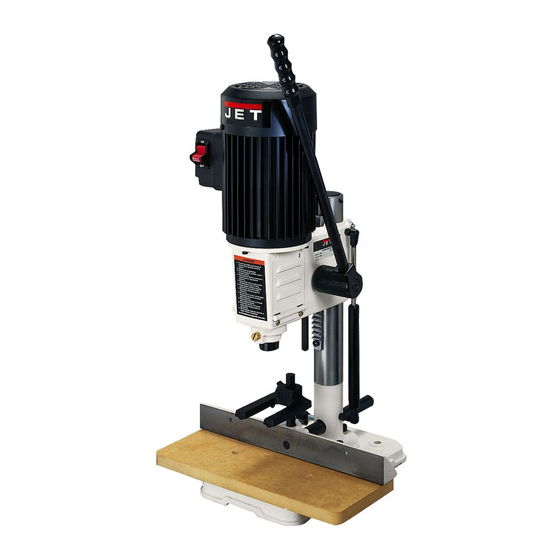
Benchtop mortiser
Hide thumbs
Also See for JBM-5:
- Operating instructions and parts manual (11 pages) ,
- Operating instructions manual (18 pages)
Table of Contents

Related Manuals for Jet JBM-5


Summary of Contents for Jet JBM-5
- Page 1 This .pdf document is bookmarked Operating Instructions and Parts Manual JBM-5 Benchtop Mortiser 427 New Sanford Road LaVergne, Tennessee 37086 Part No. M-708580 Ph.: 800-274-6848 Revision H 08/2017 www.jettools.com Copyright © 2017 JET...
-
Page 2: Warranty And Service
JET sells through distributors only. The specifications listed in JET printed materials and on official JET website are given as general information and are not binding. JET reserves the right to effect at any time, without prior notice, those alterations to parts, fittings, and accessory equipment which they may deem necessary for any reason ®... -
Page 3: Table Of Contents
This machine has been designed and constructed to provide consistent, long-term operation if used in accordance with instructions set forth in this manual. If there are questions or comments, please contact your local supplier or JET. JET can also be reached at our web site: www.jettools.com. -
Page 4: Important Safety Instructions
4.0 IMPORTANT SAFETY INSTRUCTIONS WARNING – To reduce risk of injury: KEEP GUARDS IN PLACE and in order. REMOVE ADJUSTING KEYS AND WRENCHES. Form the habit of checking to see that keys and adjusting wrenches are removed from the tool before turning it on. KEEP THE WORK AREA CLEAN. -
Page 5: Electrical Requirements
22. WARNING: Drilling, sawing, sanding or machining wood products generates wood dust and other substances known to the State of California to cause cancer. Avoid inhaling dust generated from wood products or use a dust mask or other safeguards to avoid inhaling dust generated from wood products. 23. -
Page 6: Specifications
L = length, W = width, H = height The above specifications were current at the time this manual was published, but because of our policy of continuous improvement, JET reserves the right to change specifications at any time and without prior notice, without incurring obligations. -
Page 7: Mounting Dimensions
6.1 Mounting dimensions Figure 6-1 7.0 Unpacking Open shipping container and check for shipping damage. Report any damage immediately to your distributor and shipping agent. Do not discard any shipping material until the Mortiser is assembled and running properly. Compare the contents of your container with the following parts list to make sure all parts are intact. -
Page 8: Assembly
Insert bar of fence assembly (J, Figure 8-2) through hole in column. Use the fence-locking 8.0 Assembly handle (J ) to adjust fence assembly. Attach the hold down (I, Figure 3) to the Never connect the machine to vertical post using wing screw (I , Figure 3). -
Page 9: Adjustments
10.0 Adjustments 10.1 On-Off switch The switch (inset photo, Figure 10-1) has a safety key that, when pulled out, allows the switch to be locked in OFF position. The key must be reinserted to start machine. Figure 10-3 10.4 Hold down adjustment The hold down (I, Figure 10-3) should be adjusted so it just touches top of workpiece and allows the workpiece to slide left or right. -
Page 10: Spindle Adaptor
Insert chisel bushing with hole facing forward (toward operator). See Figure 10-6. Tighten screw just enough to hold chisel bushing in place. Insert bit into chisel, and use a block of wood to push chisel upward as far as possible into head. -
Page 11: Adjusting Chisel Parallel To Workpiece
JET. Some parts are shown for reference chips will not be able to clear the chisel. only, and may not be available individually. -
Page 12: Jbm-5 Benchtop Mortiser - Exploded View
14.1 JBM-5 Benchtop Mortiser – Exploded View... -
Page 13: Jbm-5 Benchtop Mortiser - Parts List
14.2 JBM-5 Benchtop Mortiser – Parts List Index No. Part No. Description Size 1 ....23011045W ....Base....................... 1 2 ....50302003 ....Lock Washer ............5/16” ......3 3 ....50102018 ....Hex Socket Cap Screw ..........M8-1.25x20 ....3 4 .... - Page 14 59 ....50322004 ....Spring Washer ............M5 ......... 1 60 ....50102002 ....Hex Socket Cap Screw ..........M5-0.8x8 ....... 1 61 ....23011076 ....Chuck Key ..................... 1 ....23010045 ....JET Label (not shown) ................... 1...
-
Page 15: Chisel Specifications
15.0 Chisel specifications ® JBM-5 Benchtop Mortiser (708580) Specifications in conjunction with our Premium Chisel and Bit Sets JET JBM-5 Mortiser with Premium Chisels 1791091 1791092 1791093 1791094 1/4” 5/16” 3/8” 1/2” chisel chisel chisel chisel Total Chisel Length (installed) 3-21/32”... - Page 16 This page intentionally left blank.
- Page 17 427 New Sanford Road LaVergne, Tennessee 37086 Phone: 800-274-6848 www.jettools.com...