
Related Manuals for HP J9827A


Summary of Contents for HP J9827A
- Page 1 HP Switch zl2 Modules Installation Guide Part Number: 5998-5076a Published: July 2016 Edition: 2...
- Page 2 HP 24-port Gig-T PoE+ v2 zl Module J9534A HP 20-port Gig-T PoE+ / 4-port SFP v2 zl Module J9535A HP 20-port Gig-T PoE+ / 2-port 10-GbE SFP+ v2 zl Module J9536A HP 24-port SFP v2 zl Module J9537A HP 8-port 10-GbE SFP+ v2 zl Module...
- Page 3 HP 5406R zl2 Switch Fan Tray J9831A HP 5412R zl2 Switch Fan Tray J9832A HP 5406R zl2 Switch Chassis J9850A HP 5412R zl2 Switch Chassis J9851A HP X450 4U/7U Universal 4-Post Rack Mounting Kit J9852A...
-
Page 4: Table Of Contents
Contents 1 HPE Switch v2 zl Modules...................6 For the HPE 5400R zl2 Switches......................6 2 Network Interface Module LEDs................9 Network Connectivity Modules Port LEDs....................9 3 Features......................10 v2 zl Module Features........................10 The v2 zl Modules have the following features:..................11 4 Installing the Modules..................12 Overview.............................12 Installing the Module in an Unused Slot.....................12 Installation Precautions.........................12... -
Page 5: Contents
Regulatory information........................40 Belarus Kazakhstan Russia marking.....................40 Turkey RoHS material content declaration..................41 Ukraine RoHS material content declaration..................41 Contents... -
Page 6: Hpe Switch V2 Zl Modules
1 HPE Switch v2 zl Modules For the HPE 5400R zl2 Switches Descriptions. The HPE Switch v2 zl Modules are the second generation zl modules and provide a variety of improved network connectivity options for the HPE 5400R zl2 switches. The following modules are currently available. - Page 7 HPE 5400R zl2 Is a management module for use Management Module with HPE 5400R series chassis (J9827A) only. Order module provides a dual, redundant deployment (base system comes with a single module) or for onsite sparing. For the HPE 5400R zl2 Switches...
- Page 8 Module Description HPE Advanced Services v2 The HPE Advanced Services v2 zl zl Module with SSD module is a converged networking, (J9858A) computing, and virtualization solution inside the 5400 zl, 8200 zl, and 5400R zl2 switch families that hosts VMware vSphere(R) compatible virtual networking or business applications inside the switch.
-
Page 9: Network Interface Module Leds
2 Network Interface Module LEDs Network Connectivity Modules Port LEDs There are two LEDs for each port: The Link LED lights green with a valid connection and orange if there is a fault or alert condition. The Mode LED lights according to the LED mode selected on the chassis. The LED mode is selected on the Management Module for the 5400R zl2 switches,. -
Page 10: Features
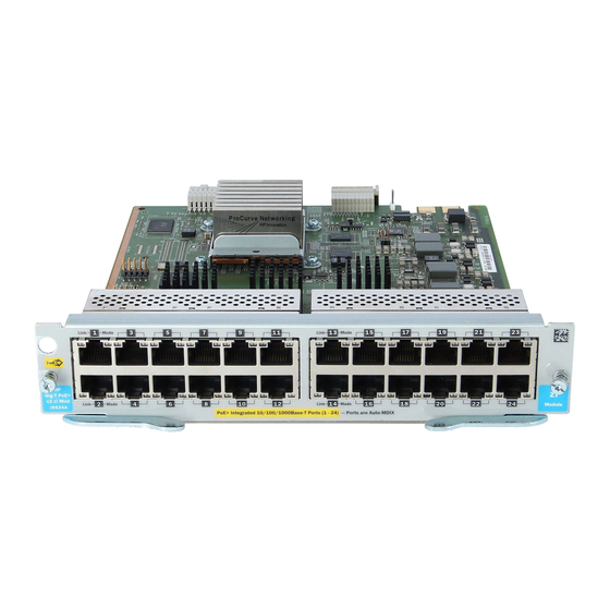
3 Features v2 zl Module Features Figure 1. Example: HP 24-port, Gig-T PoE+ v2 zl Module The following table shows the label and description for HP 24-port Gig-T PoE+ v2 zl Module: Label Description 1 and 2 Link and Mode LEDs (one pair per port) -
Page 11: The V2 Zl Modules Have The Following Features
The v2 zl Modules have the following features: All v2 zl modules share the following features: ◦ auto-enabled ports—the ports are all configured to be ready for network operation as soon as a viable network cable is connected ◦ auto-configuration—a default configuration is applied to the module when the switch is powered on and the module passes self test;... -
Page 12: Installing The Modules
4 Installing the Modules Overview Before installing any module, ensure you have loaded the most current software for that module onto your switch, see HPE Switch v2 zl Modules for the V2 modules software version. You can install any of the modules into any of the HPE networking chassis zl switches that have compatible module slots. -
Page 13: Installation Procedures
Ensure you fully insert the modules. That is, press the module into the slot until the bulkhead on the module is contacting or is very close to contacting the front face of the switch chassis. Once the module is fully inserted, make sure you screw in the two retaining screws to secure the module in place. -
Page 14: Installing Or Removing A Sfp Transceiver
The following table shows label and description on how to install a module: Label Description 1, 3 Insert module into the guides and slide it in until it is fully inserted. Close extractor handles Figure 4. Module fully Installed Installing or Removing a SFP transceiver You can install or remove a SFP transceiver from the SFP v2 zl Module without having to power off the switch. -
Page 15: Verifying The Module Is Installed Correctly
Figure 5. Example: SFP transceiver being installed Removing the SFP transceivers: Disconnect the network cable from the transceiver before removing it from the module. Depending on when you purchased your transceiver, it may have either of three different release mechanisms: a plastic tab on the bottom, a wire bail, or a plastic collar. -
Page 16: Connecting The Network Cables
The following table shows the label and description for 5400R zl2 switch with LED status as ON: Label Description Fault LED Module Link and Mode LEDs Module Status LEDs When the module is installed properly and the switch is powered on, or the module is installed when the switch already has power, the module undergoes a self test that takes a few seconds. -
Page 17: Verifying The Network Connections Are Working
Module NOTE: The RJ-45 ports on this module have the Auto-MDIX feature. In the module’s default configuration, Auto, either a straight-through or crossover cable can be used to connect the module to any other 100Base-T, or 10Base-TX device. See the Note in Automatic Cable Sensing on Twisted-Pair Ports Since the 10Base-T operation is through the 10/100Base-TX ports, if you ever want to upgrade the ports to 100Base-TX, it would be best to cable the parts initially with category 5 cable. -
Page 18: Default Port Configuration
Figure 7. Example: Link and Mode LEDs The following table lists the label and description of Link and Mode LEDs: Label Description 1, 2 Link and Mode LEDs The Link LED will be lit for each port that is connected properly to an active network device. If the Link LED does not go on when an active network cable is connected to the port, there may be something wrong with the cable, the cable connectors, or the device at the other end of the cable. - Page 19 The default port configurations for connection parameters are: Ports Enabled: Yes Mode: ◦ 10/100/1000-T v2zl Modules: Auto — The port auto negotiates speed (10, 100 or 1000 Mbps), communication mode (half or full duplex), and MDI or MDI-X port operation. NOTE: If you configure the port to one of the fixed 100 Mbps modes, the port will then operate only as an MDI-X port.
-
Page 20: Replacing Or Removing A Module
5 Replacing or Removing a Module Follow these procedures to replace one module with another, or to remove a module without replacing it: Remove any network cables from the ports on the module. If the module you want to remove has a shutdown button, make sure to shut down the module before removing it either by using the CLI shutdown command or by using the shutdown button. - Page 21 Run the command “no module <slot>” to switch configuration, if you are exchanging one type of module with a different type of module in the same slot. Issue the “reload module x” command, where x is the letter of the slot (A through L). The following warning will be displayed: WARNING! The reload module command will shut down the specified modules and...
-
Page 22: Troubleshooting
6 Troubleshooting One of the primary tools for troubleshooting the switch modules are the LEDs on the front of the switch and on the modules. Refer to “LED Behavior” on LED Behavior for a description of the normal LED behavior. Also, refer to the switch Installation and Getting Started Guide for more detailed troubleshooting information for the switch. -
Page 23: Customer Support Services
24 hours a day, seven days a week through the use of a number of automated electronic services. For more information, visit www.hpe.com/networking/support. Additionally, your HP-authorized network reseller can also provide you with assistance, both with services they offer and with services offered by HPE. -
Page 24: Specifications
0°C to 45°C (32°F to 113°F) -40°C to 70°C (-40°F to 158°F) J9868A 0°C to 45°C (32°F to 113°F) -40°C to 70°C (-40°F to 158°F) J9827A 0°C to 45°C (32°F to 113°F) -40°C to 70°C (-40°F to 158°F) J9828A 0°C to 45°C (32°F to 113°F) -40°C to 70°C (-40°F to 158°F) -
Page 25: Network Connectivity Speeds And Technologies
Modules Temperature Relative humidity: 15% to 95% at 40°C (104°F) 15% to 90% at 65°C (149°F) (non-condensing) J9154x only 15% to 90% at 40°C (104°F) 15% to 90% at 65°C (149°F) Maximum altitude: 3.0 km (10,000 ft) 4.6 km (15,000 ft) Network Connectivity Speeds and Technologies Table 2 Optional Network Connectivity, Speeds and Technologies Transceiver Form-Factor and Connector... -
Page 26: Technology Standards And Safety Compliance
Technology Standards and Safety Compliance Table 3 Technology Standards and Safety Compliance Laser safety information Compatible with these EN/IEC Media IEEE standard Converter Technology standards compliance SFP Lasers X2 Lasers SFP+Lasers Lasers 10-T IEEE 802.3 10BASE-T 100-TX IEEE 802.3u 100BASE-TX 1000-T IEEE 802.3ab 1000BASE-T... -
Page 27: Cabling And Technology Specifications
Table 3 Technology Standards and Safety Compliance (continued) Laser safety information Compatible with these EN/IEC Media IEEE standard Converter Technology standards compliance SFP Lasers X2 Lasers SFP+Lasers Lasers 10-Gig LR IEEE 802.3ae EN/IEC 60825 Class 1 Laser Class 1 10GBASE-LR Product Laser Product... - Page 28 Table 4 Cabling Specifications (continued) and ISO/IEC 793-2 Type A1b or A1a standards respectively. 9/125 μm (core/cladding) diameter, low metal content fiber-optic cables, complying with the Single mode fiber ITU-T G.652 and ISO/IEC 793-2 Type B1 standards. A mode conditioning patch cord may be needed for some Gigabit-LX and 10-Gigabit LRM installations. Specifications...
- Page 29 Mode Conditioning Patch Cord for more information. Note on 1000BASE-T Cable Requirements: The Category 5 networking cables that work for 100BASE-TX connections should also work for 1000BASE-T, as long as all four-pairs are connected. But, for the most robust connections, you should use cabling that complies with the Category 5e specifications, as described in Addendum 5 to the TIA-568-A standard (ANSI/TIA/EIA-568-A-5).
-
Page 30: Technology Distance Specifications
Technology Distance Specifications Table 5 Technology Distance Specifications Multimode fiber modal Technology Supported cable type bandwidth Supported distances 100-FX multimode fiber up to 2,000 meters 100-BX single mode fiber 0.5 - 10,000 meters 1000-T twisted-pair copper up to 100 meters 10GBASE-T twisted-pair copper Cat 6 unshielded - up to 55... -
Page 31: Mode Conditioning Patch Cord
Mode Conditioning Patch Cord The following information applies to installations in which multimode fiber-optic cables are connected to a Gigabit-LX port or a 10-Gigabit LRM port. Multimode cable has a design characteristic called “Differential Mode Delay”, which requires the transmission signals be “conditioned”... -
Page 32: Emc Regulatory Statements
9 EMC Regulatory Statements U.S.A. FCC Class A This equipment has been tested and found to comply with the limits for a Class A digital device, pursuant to Part 15 of the FCC Rules. These limits are designed to provide reasonable protection against interference when the equipment is operated in a commercial environment. -
Page 33: Taiwan
Taiwan European Community Declaration of Conformity These products are designed for operation with the HPE switches that have zl module slots. Please see the Declarations of Conformity included in the Installation Guides for those products. NOTE: For Conducted and Radiated Immunity in accordance with EN55024, the HPE 8-port 10GBase-T v2 zl Module (J9546A) is limited to Performance Criteria A with shielded cable (Cat 6/6A). -
Page 34: Waste Electrical And Electronic Equipment (Weee) Statements
10 Waste Electrical and Electronic Equipment (WEEE) Statements Disposal of Waste Equipment by Users in Private Household in the European Union This symbol on the product or on its packaging indicates that this product must not be disposed of with your other household waste. - Page 35 Entsorgung von Altgeräten aus privaten Haushalten in der EU Das Symbol auf dem Produkt oder seiner Verpackung weist darauf hin, dass das Produkt nicht über den normalen Hausmüll entsorgt werden darf. Benutzer sind verpflichtet, die Altgeräte an einer Rücknahmestelle für Elektro- und Elektronik-Altgeräte abzugeben. Die getrennte Sammlung und ordnungsgemäße Entsorgung Ihrer Altgeräte trägt zur Erhaltung der natürlichen Ressourcen bei und garantiert eine Wiederverwertung, die die Gesundheit des Menschen und die Umwelt schützt.
- Page 36 Verwijdering van afgedankte apparatuur door privé-gebruikers in de Europese Unie Dit symbool op het product of de verpakking geeft aan dat dit product niet mag worden gedeponeerd bij het normale huishoudelijke afval. U bent zelf verantwoordelijk voor het inleveren van uw afgedankte apparatuur bij een inzamelingspunt voor het recyclen van oude elektrische en elektronische apparatuur.
-
Page 38: Support And Other Resources
Hewlett Packard Enterprise Support Center More Information on Access to Support Materials page: www.hpe.com/support/AccessToSupportMaterials IMPORTANT: Access to some updates might require product entitlement when accessed through the Hewlett Packard Enterprise Support Center. You must have an HP Passport set up with relevant entitlements. Websites Website Link Hewlett Packard Enterprise Information Library www.hpe.com/info/enterprise/docs... -
Page 39: Customer Self Repair
Subscription Service/Support Alerts www.hpe.com/support/e-updates Software Depot www.hpe.com/support/softwaredepot Customer Self Repair www.hpe.com/support/selfrepair Insight Remote Support www.hpe.com/info/insightremotesupport/docs Serviceguard Solutions for HP-UX www.hpe.com/info/hpux-serviceguard-docs Single Point of Connectivity Knowledge (SPOCK) Storage www.hpe.com/storage/spock compatibility matrix Storage white papers and analyst reports www.hpe.com/storage/whitepapers Customer self repair Hewlett Packard Enterprise customer self repair (CSR) programs allow you to repair your product. -
Page 40: A Warranty And Regulatory Information
A Warranty and regulatory information For important safety, environmental, and regulatory information, see Safety and Compliance Information for Server, Storage, Power, Networking, and Rack Products, available at www.hpe.com/support/Safety-Compliance-EnterpriseProducts. Warranty information HPE ProLiant and x86 Servers and Options www.hpe.com/support/ProLiantServers-Warranties HPE Enterprise Servers www.hpe.com/support/EnterpriseServers-Warranties HPE Storage Products www.hpe.com/support/Storage-Warranties... -
Page 41: Turkey Rohs Material Content Declaration
Local representative information Kazakh: Russia: Belarus: Kazakhstan: Manufacturing date: The manufacturing date is defined by the serial number. CCSYWWZZZZ (serial number format for this product) Valid date formats include: YWW, where Y indicates the year counting from within each new decade, with 2000 as the starting point;...