Raymarine RAY90 Installation And Operation Instruction Manual
Hide thumbs
Also See for RAY90:
- Installation & operation instructions (108 pages) ,
- Installation & operating instruction (107 pages) ,
- User manual (96 pages)

Related Manuals for Raymarine RAY90


Summary of Contents for Raymarine RAY90
- Page 1 RAY90/91 VHF Installation and operation instructions English (en-US) Date: 05-2018 Document number: 81377-2 © 2018 Raymarine UK Limited...
- Page 3 Software updates Check the Raymarine website for the latest software releases for your product. www.raymarine.com/software Product documentation The latest versions of all English and translated documents are available to download in PDF format from the website: www.raymarine.com/manuals.
-
Page 5: Table Of Contents
USA licensing requirements ....................21 Canada licensing requirements .................... 21 Europe and rest of world licensing requirements..............21 Additional information — Ray90 / Ray91 ................21 Additional information - wireless handset................21 Additional information - wireless charging holster............... 22 Additional information - wireless hub .................. 22 Additional information - wireless speaker................ - Page 6 3.1 Selecting a location......................28 General location requirements .................... 28 Antenna mounting and EME exposure ................29 Wireless product location requirements ................29 3.2 EMC installation guidelines....................30 Suppression ferrites......................30 Connections to other equipment ..................30 3.3 Product dimensions ......................31 Product dimensions - Base station ..................
- Page 7 4.7 NMEA 0183 connection ....................58 4.8 Loud hailer connection ..................... 59 4.9 Connecting GNSS (GPS) and VHF antennas ..............60 4.10 Wireless hub connection ....................61 4.11 Wireless handset charging holster – power connection ..........62 In-line fuse and thermal breaker ratings ................62 4.12 Wireless handset connections ..................
- Page 8 Connecting a wireless handset to the hub ................95 Connecting the wireless speaker to the Wireless handset...........97 Wireless set-up menu options ..................... 98 Chapter 7 Digital selective calling (DSC) ..............99 7.1 Digital Selective Calling (DSC) ..................100 7.2 Distress calls ........................102 Making a designated distress call..................
- Page 9 7.11 DSC set-up menu options ....................116 Chapter 8 VHF operations .....................117 8.1 Watch modes........................118 Setting Watch mode ......................118 8.2 Scan Mode .........................119 Setting Scan mode ......................119 8.3 Priority channels .......................120 Switching between priority channels.................. 120 Setting a second priority channel ..................120 8.4 Sensitivity ...........................121 Switching sensitivity modes....................
- Page 10 11.6 GNSS (GPS) troubleshooting..................144 GNSS (GPS) data output ..................... 144 11.7 Wireless troubleshooting ....................145 Chapter 12 Technical support..................147 12.1 Raymarine product support and servicing..............148 12.2 Viewing product information ..................150 12.3 Learning resources ......................151 Chapter 13 Technical specification ................153 13.1 Technical specification —...
-
Page 11: Chapter 1 Important Information
Certified Installation Raymarine recommends certified installation by a Raymarine approved installer. A certified installation qualifies for enhanced product warranty benefits. Contact your Raymarine dealer for further details, and refer to the separate warranty document packed with your product. Warning: Product installation and operation •... -
Page 12: Fcc Interference Statement (Part 15.105 (B))
This device may not cause harmful interference. 2. This device must accept any interference received, including interference that may cause undesired operation. FCC Interference Statement (Part 15.105 (b)) This equipment has been tested and found to comply with the limits for a Class B digital device, pursuant to Part 15 of the FCC Rules. -
Page 13: Water Ingress
Raymarine. Raymarine is not responsible for damages or injuries caused by your use or inability to use the product, by the interaction of the product with products manufactured by others, or by errors in information utilized by the product supplied by third parties. -
Page 14: Warranty Registration
In addition, our policy of continuous product improvement may change specifications without notice. As a result, Raymarine cannot accept liability for any differences between the product and this document. Please check the Raymarine website (www.raymarine.com) to ensure you have... -
Page 15: Chapter 2 Document And Product Information
Chapter 2: Document and product information Chapter contents • 2.1 Product documentation on page 16 • 2.2 Applicable products on page 17 • 2.3 Product overview on page 18 • 2.4 Parts supplied on page 19 • 2.5 Licensing on page 21 •... -
Page 16: Product Documentation
87357 template Wired handset holster mounting template 87359 All documents are available to download in pdf format from the Raymarine® website: www.raymarine.com/manuals. User manuals Print Shop Raymarine provides a Print Shop service, enabling you to purchase a high-quality, professionally-printed manual for your Raymarine product. -
Page 17: Applicable Products
The following optional components can be purchased to create a second wired handset station. Part number Description A80289 Wired handset Note: To be compatible with the Ray90 / Ray91, the Wired handset must be running software version V1.23 or greater. A80542 Wired speaker (passive) Extension cables... -
Page 18: Product Overview
2.3 Product overview The Ray90 and Ray91 are 12 V dc, Class D Digital Selective Calling (DSC) VHF radios. DSC enables you to make and receive calls to a specific radio, and to transmit and receive position information to and from a selected radio. DSC also allows transmission of a distress alert, to all radios within range, at the touch of a button. -
Page 19: Parts Supplied
The following parts are supplied with your product. Please ensure your box contents are correct before proceeding with the installation. Ray90 / Ray91 VHF DSC Radio base station (including fitted power and data cable). 2. Wired handset holster. 3. Wired handset. -
Page 20: Additional Parts Supplied
The following additional parts are supplied with your product. These parts are to be used when installing your Ray90 / Ray91 base station on a metal surface. Insulation sheet (To be fitted between base station and a metal mounting surface). -
Page 21: Licensing
It is your responsibility to determine whether a license is required in your area before operating this equipment. Additional information — Ray90 / Ray91 The following additional information is required for completing a license application in Canada and the USA. -
Page 22: Additional Information - Wireless Charging Holster
Note: ISED previously IC (Industry Canada) Additional information - wireless charging holster ISED ID: 4069B–RAYCGR FCC ID: PJ5–RAYCGR FCC type accepted Parts, 2, 15 and 80 Output power 5 watt Modulation Frequency 110KHz to 205KHz Note: ISED previously IC (Industry Canada) Additional information - wireless hub ISED ID: 4069B–RAYHUB... -
Page 23: Obtain Mmsi (Maritime Mobile Service Identity) Number
If a MMSI number is not entered, the DSC functionality of your radio will be disabled. In the United States of America, the MMSI and Static Data must be entered only by a Raymarine® dealer or other appropriately qualified installer of marine communications equipment on board vessels. -
Page 24: Automatic Transmitter Identification System (Atis)
2.7 Automatic Transmitter Identification System (ATIS) Your product includes ATIS functionality for use on the inland waterways of contracting governments “Regional Arrangement on the Radiocommunication Service for Inland Waterways” of the — also “RAINWAT” known as ATIS adds data at the end of radio transmissions that identifies your station. ATIS operation can be turned on or off as needed via the radio’s menu. -
Page 25: Software Updates
2.8 Software updates Raymarine periodically releases software updates for its products. These updates can provide new and enhanced features and also improve product performance and usability. You should ensure that you have the latest software for your products by regularly checking the website for new software. -
Page 26: Performing Software Updates - Wireless Handset
7. When the update is complete, check your radios software version. 8. Removed the memory card from the card reader. Performing software updates — Wireless handset 1. Prior to performing the software update process, ensure that the Wireless handset is plugged into its charging holster. -
Page 27: Chapter 3 Installation
Chapter 3: Installation Chapter contents • 3.1 Selecting a location on page 28 • 3.2 EMC installation guidelines on page 30 • 3.3 Product dimensions on page 31 • 3.4 Mounting on page 36 Installation... -
Page 28: Selecting A Location
3.1 Selecting a location Warning: Potential ignition source This product is NOT approved for use in hazardous/flammable atmospheres. Do NOT install in a hazardous/flammable atmosphere (such as in an engine room or near fuel tanks). General location requirements When selecting a location for the unit it is important to consider a number of factors. Ventilation requirements To provide adequate airflow: •... -
Page 29: Antenna Mounting And Eme Exposure
Ensure that your VHF antenna is connected to the radio before transmission. Raymarine® declares a Maximum Permissible Exposure (MPE) radius of 1.8 meters (5.9 ft.) for this system, assuming 25 watts output to an omnidirectional antenna of 3dBi gain or less. -
Page 30: Emc Installation Guidelines
Requirement for ferrites on non-Raymarine cables. If your product is to be connected to other equipment using a cable not supplied by Raymarine, a suppression ferrite MUST always be attached to the end of the cable nearest to the Raymarine... -
Page 31: Product Dimensions
3.3 Product dimensions Product dimensions - Base station The Base station dimensions are listed below. 217 mm (8.54 in) 9.5 mm (0.37 in) 235.95 mm (9.29 in) 104 mm (4.09 in) 149.95 mm (5.91 in) 30 mm (1.18 in) 14 mm (0.55 in) 90 mm (3.54 in) 61 mm (2.40 in) The Base station includes a fitted power cable and data cable, The power cable length is 1.2 m (3.94... -
Page 32: Product Dimensions - Speakers
Product dimensions - speakers The dimensions for the Passive and Active speakers are shown below. 118.5 mm (4.67 in) 112.5 mm (4.43 in) 18.3 mm (0.72 in) 26.4 mm (1.04 in) 25 mm (0.98 in) 30.6 mm (1.20 in) The Passive speaker includes a fitted 2 m (6.56 ft) audio cable terminated with a male RCA plug. The Active speaker includes a fitted 2 m (6.56 ft) power cable terminated with a spade connectors. -
Page 33: Product Dimensions - Wired Handset (Raymic)
Product dimensions - Wired handset (Raymic) 167.34 mm (6.59 in) 151 mm (5.94 in) 66.9 mm (2.63 in) 70 mm (2.76 in) 46.7 mm (1.84 in) The Wired handset is fitted with a coiled cable. Ensure sufficient space is available below the desired mounting area to accommodate the cable. -
Page 34: Product Dimensions - Wireless Hub
244.99 mm (9.65 in) The Wireless hub includes a fitted 5 m (16.4 ft) cable for connection to the Ray90 / Ray91 Base station. If the installation requires the cable to be passed through a bulkhead or panelling a 20 mm (0.79 in) -
Page 35: Product Dimensions - Wireless Handset And Holster
Product dimensions - Wireless handset and holster 173.33 mm (6.82 in) 50.5 mm (1.99 in) 71.41 mm (2.81 in) The charging holster is supplied with a fitted 2 meter (6.56 ft) power cable terminated with bare ended wires. Installation... -
Page 36: Mounting
3.4 Mounting Tools required for installation Power drill 2. Pozi-drive screwdriver 3. Adhesive tape 4. Suitable size drill bit 5. 89 mm (3 ½ in) Hole saw (used for speaker mounting) 6. File (for speaker cut-out) Mounting the Base station Before mounting, ensure that your selected location meets the location requirements found in this document. -
Page 37: Wired And Wireless Speaker Mounting
1. Using the supplied mounting template, mark the location of the fixing holes on the mounting surface. 2. Drill holes for the mounting fixings using a drill with a suitable sized drill bit. 3. Screw the fixings approximately half way into the holes in the mounting surface. 4. -
Page 38: Handset (Wired) Mounting Using The Holster
1. Remove the speaker’s bezel. 2. Using the supplied mounting template, mark the location of the cut out and fixing holes on the mounting surface. 3. Using a 89 mm (3 ½ in) hole saw, drill out the centre cut out area indicated on the mounting template. -
Page 39: Pass-Through Panel Kit Mounting
1. Check the selected location for the mounting holster, a clear flat area is required, with sufficient space around it to place and remove the Handset. 2. Using a pencil, offer up the holster to the desired location and mark the location of the screw holes on the mounting surface. - Page 40 Splash-proof dust cap with lanyard Mounting plate fixings x 3 Mounting plate nut Mounting plate Mounting plate gasket Extension cable 1. Check the selected location for the Mounting plate, a clear flat area is required. 2. Using a pencil, offer up the Mounting plate to the desired location and mark the location of the screw holes and the center hole on the mounting panel.
-
Page 41: Mounting The Wireless Hub
Note: Drill bit, tap size and tightening torque is dependent on the thickness and type of material the unit is to be mounted on. Mounting the wireless hub Before mounting, ensure that: • your selected location meets the location requirements found in this document. •... - Page 42 Antenna orientation Radio waves are emitted from the wireless hub perpendicular to the orientation of the hub’s antenna. Keeping the antenna vertical should provide the best coverage for devices on the same plane as your hub. Positioning the antenna horizontally will provide better coverage above and below the hub. Installing the wireless hub antenna extension accessory An extension cable accessory (A80541) is available for the wireless hub’s antenna.
- Page 43 2. Using a pencil, offer up the Mounting plate to the desired location and mark the location of the screw holes and the center hole on the mounting panel. 3. Drill holes for the mounting fixings using a drill with a suitable sized drill bit. 4.
-
Page 45: Chapter 4 Cables And Connections
Chapter 4: Cables and connections Chapter contents • 4.1 General cabling guidance on page 46 • 4.2 Connections overview on page 48 • 4.3 Power connection on page 50 • 4.4 Handset station connection on page 54 • 4.5 Wired speaker connection on page 55 •... -
Page 46: General Cabling Guidance
• Unless otherwise stated use only standard cables of the correct type, supplied by Raymarine. • Ensure that any non-Raymarine cables are of the correct quality and gauge. For example, longer power cable runs may require larger wire gauges to minimize voltage drop along the run. -
Page 47: Dust Caps
Connections to other equipment Requirement for ferrites on non-Raymarine cables If your Raymarine equipment is to be connected to other equipment using a cable not supplied by Raymarine, a suppression ferrite MUST always be attached to the cable near the Raymarine unit. -
Page 48: Connections Overview
4.2 Connections overview Connection Connects to Suitable cables GNSS (GPS) antenna Passive GNSS antenna GNSS antenna’s fitted cable. connection Earth stud DO NOT CONNECT VHF antenna connection VHF antenna or Splitter VHF antenna’s fitted cable. Power and data connection • 12 V dc power supply •... - Page 49 Unused bare ended wires Any unused bare ended wires should be folded back and wrapped in insulation tape. Cables and connections...
-
Page 50: Power Connection
7 A (if only connecting one device) Note: • The suitable fuse rating for the thermal breaker is dependent on the number of devices you are connecting. If in doubt consult an authorized Raymarine dealer. ® • Your product’s power cable may have a fitted in-line fuse. If not, add an in-line fuse to the positive wire of your product’s power connection. -
Page 51: Power Distribution
The information provided below is for guidance only, to help protect your product. It covers common vessel power arrangements, but does NOT cover every scenario. If you are unsure how to provide the correct level of protection, please consult an authorized Raymarine dealer or a suitably qualified professional marine electrician. - Page 52 Battery connection scenario A: suitable for a vessel with a common RF ground point. In this scenario, if your product’s power cable is supplied with a separate drain wire then it should be connected to the vessel’s common ground point. Battery connection scenario B: suitable for a vessel without a common grounding point.
- Page 53 Positive (+) bar Negative (-) bar Circuit breaker Fuse • In all cases, observe the recommended breaker / fuse ratings provided in the product’s documentation. Important: Be aware that the suitable fuse rating for the thermal breaker or fuse is dependent on the number of devices you are connecting.
-
Page 54: Handset Station Connection
4.4 Handset station connection A Wired handset can be connected to each Handset station connection (HS 1 / HS 2). Your radio is supplied with the equipment to create a full handset station (i.e.: Wired handset, Adaptor cable and Passive speaker). Additional accessories can be purchased to create a second wired handset station. Base station 2. -
Page 55: Wired Speaker Connection
4.5 Wired speaker connection A wired speaker can be connected to a wired handset station using the RCA audio connector, available on the Handset adaptor cable. Wired handset adaptor cable 400 mm (1.3 ft) (1 x supplied and available as an accessory: A80297) 2. -
Page 56: Nmea 2000 / Seatalkng ® Connection
4.6 NMEA 2000 / SeaTalkng ® connection Your product can transmit data to devices connected on SeaTalkng ® or NMEA 2000 CAN bus networks. Connection is established using the DeviceNet connector located on the bottom of the unit. Use the supplied DeviceNet to SeaTalkng ® adaptor to connect your product to your SeaTalkng ® backbone using available SeaTalkng ®... -
Page 57: Connecting Seatalkng ® Cables
Connecting SeaTalkng ® cables 1. Rotate the locking collar so it is in the unlocked position. 2. Ensure the cable’s connector is correctly oriented. 3. Fully insert the cable connector. 4. Rotate locking collar clockwise (2 clicks) until it is in the locked position. Cables and connections... -
Page 58: Nmea 0183 Connection
4.7 NMEA 0183 connection The NMEA 0183 wires can be used to connect the unit to a NMEA 0183 GNSS (GPS) receiver or MFD. Yellow = Receive positive (+) wire 2. Green = Receive negative (-) wire 3. White = Transmit positive (+) wire 4. -
Page 59: Loud Hailer Connection
4.8 Loud hailer connection A Loud hailer (M95435) can be connected to the radio using the loud hailer wires. Positive (+) hailer wire (Purple) Negative (-) hailer wire (Gray) Cables and connections... -
Page 60: Connecting Gnss (Gps) And Vhf Antennas
4.9 Connecting GNSS (GPS) and VHF antennas The radio must be connected to suitable GNSS and VHF antennas (not supplied). The antenna connections must be protected so it cannot come into contact with any grounded bare metal. Pre-requisites: • Ensure you have installed your antennas in accordance with the instructions supplied with the antennas. -
Page 61: Wireless Hub Connection
4.10 Wireless hub connection The Wireless hub connects directly to the Ray90 / Ray91’s Hub connection. The Wireless hub is required to allow connection of wireless handset stations to the Ray90 / Ray91 base station. Cables and connections... -
Page 62: Wireless Handset Charging Holster - Power Connection
In-line fuse rating Thermal breaker rating 2 A (refer to note below) Note: • The suitable fuse rating for the thermal breaker is dependent on the number of devices you are connecting. If in doubt consult an authorized Raymarine dealer. ®... -
Page 63: Wireless Handset Connections
4.12 Wireless handset connections The Wireless handset connects wirelessly to the Wireless hub, and the Wireless speaker connects wirelessly to the Wireless handset. Up to 3 Wireless handsets can be connected to the Wireless hub. Refer to Connecting a wireless handset to the hub for the connection procedure. -
Page 64: Wireless Speaker - Power Connection
Thermal breaker rating 1.25 A 1.25 A (refer to note below) Note: • The suitable fuse rating for the thermal breaker is dependent on the number of devices you are connecting. If in doubt consult an authorized Raymarine ® dealer. -
Page 65: Chapter 5 Getting Started
Chapter 5: Getting started Chapter contents • 5.1 Handset controls on page 66 • 5.2 Powering the Base station on page 68 • 5.3 Homescreen overview on page 69 • 5.4 Multiple station operation on page 76 • 5.5 Adjusting Brightness and Contrast on page 77 •... -
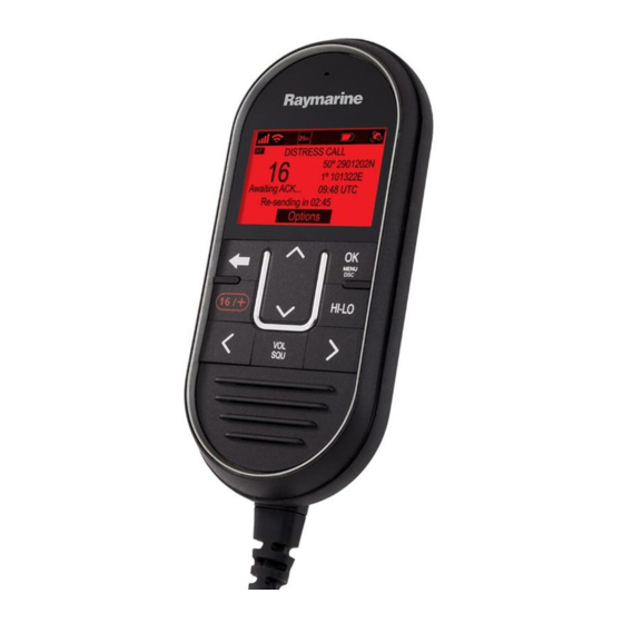
Page 66: Handset Controls
5.1 Handset controls The Handset’s controls are shown below. Power — Press to power the handset on. Press and hold for 3 seconds to power the handset off. Momentary press to access the shortcut list. 2. PTT(Push to Talk) — Press and hold to send a voice message. Release to return to receive mode. Note: The maximum transmit time is limited to 5 minutes to prevent un-intentional transmissions from occupying the VHF channel. -
Page 67: Wireless Speaker Controls
Wireless speaker controls The controls for the Wireless active speaker are shown below. On/Off and volume control — Turn clockwise to turn on and then increase speaker volume. Turn counter-clockwise to decrease volume and then turn off. 2. Pairing button — Press to place speaker in pairing mode. Pressing the Pairing button will also disconnect the speaker from the device it is currently connected to. -
Page 68: Powering The Base Station
5.2 Powering the Base station The Base station automatically powers up when connected to a suitable power supply. The Base station is powered down by unplugging from the power supply or, if applicable, by tripping it’s circuit breaker. Powering the handset To power the Handset on and off follow the steps below. -
Page 69: Homescreen Overview
5.3 Homescreen overview The information below describes the on-screen characters and symbols which are shown on the Homescreen.. Status bar — The status bar displays symbols which indicate the current status of the unit. 2. Frequency band — Indicates which channel frequency band is in use: •... -
Page 70: Status Bar Symbols
Status bar symbols The status bar is used to display symbols that indicate the radio’s status. Symbol Name Description Low power Indicates the radio transmitters is in low power (1 watt) or high power (25 watt) mode High power Local Indicates the radio is in local reception mode, which decreases receiver sensitivity in high traffic... - Page 71 Symbol Name Description Receive Indicates the radio is currently receiving a transmission Weather Indicates that the weather alerts mode is activated. Power supply voltage too low Indicates the power supply to the radio is below the specified operating voltage. Power supply voltage too high Indicates the power supply to the radio is above the specified operating voltage.
-
Page 72: Main Menu Overview
Symbol Name Description Indicates that a DSC call has been received GPS Fix Indicates if the radio has a GPS/GNSS fix. Main menu overview The main menu is accessed by Pressing the OK button from the Homescreen. Currently selected menu item 2. - Page 73 Symbol Name Sub-options * DSC Calls • Individual call • Distress call • Position request • Group call • All ships call • Phonebook • Call logs • Test call • DSC set-up * Watch Mode • Dual watch • Triple watch •...
- Page 74 Symbol Name Sub-options • Hailer ** Hailer/Fog horn • Fog horn ** Intercom • Intercom • Display set-up Set-up • Language • Units • Power output • Sensitivity • Noise cancelling (Tx) • ** Wireless set-up • Handset name • Key beep •...
- Page 75 Dealer set-up menu options With authorised Dealer hardware connected the Dealer set-up menu will be available from the Main menu. Menu item Description Options Edit screen MMSI Enables editing or removal of the stored MMSI number. Edit screen ATIS Enables editing or removal of the stored ATIS ID.
-
Page 76: Multiple Station Operation
5.4 Multiple station operation When more than one handset station is connected, other handsets become “repeater” displays and will mirror the display of the handset in use. Other handsets cannot take control of the radio whilst another handset in use. Other handsets can take control of the radio after the last used handset has been inactive for 3 seconds or more. -
Page 77: Adjusting Brightness And Contrast
2. Select Backlight or Contrast. 3. Adjust the Backlight or Contrast to the desired level using: i. Channel Up / Channel Down buttons on a Ray60, Ray70, Ray90, Ray91. ii. Rotary knob on a Ray50, Ray52, Ray60, Ray70, or 4. Press the Back button to return to the previous screen. -
Page 78: Shared Brightness
5.6 Shared Brightness You can set up Shared Brightness groups which enables simultaneous brightness adjustment of all units that are part of the same group. The following products are compatible with Shared Brightness: • LightHouse™ 3 MFDs using software version 3.4 or greater. •... - Page 79 If Shared Brightness is already enabled then selecting this menu item will disable Shared Brightness. 3. Select Group. 4. Select the group that you want to assign the radio to. Adjusting the Brightness setting will now change the brightness of all products assigned to that group. Getting started...
-
Page 80: Initial Set Up
5.7 Initial set up Unless your radio has been pre-programmed; the first time you power-up your radio you will be requested to select certain options. With the exception of your MMSI and ATIS ID, you will also be requested to enter these options after a factory reset. After acknowledging the startup screen, unless previously set you will be prompted to make the following selections: Language selection —... -
Page 81: Selecting A Language
5.8 Selecting a language The language the radio uses can be changed. From the Main menu: 1. Select Set-up. 2. Select Language. The languages available are: • English (default) — English • Español — Spanish • Français — French • Deutsch — German •... -
Page 82: Switching On The Ais Receiver
5.9 Switching on the AIS receiver If your radio includes a built-in AIS receiver then it can be enabled and disabled as follows: From the Main menu: 1. Select Set-up. 2. Select AIS. 3. Select On to switch the receiver on, or select Off to switch the receiver off. -
Page 83: Selecting A Network Type
5.10 Selecting a network type When connecting your radio to other devices it is important to ensure you select the network connection and type that you want data to be transmitted over. From the Main menu: 1. Select Set-up. 2. Select Network output. The following network types are available: •... -
Page 84: Entering Your Mmsi Number
5.11 Entering your MMSI number To program your radio with your MMSI number follow the steps below. From the Set-up menu: (Menu > Set-up) 1. Select DSC set-up. 2. Select MMSI. The MMSI required message will be displayed if no MMSI number has been set. 3. - Page 85 Caution: MMSI and ATIS ID entry You can only enter the MMSI number and ATIS ID once! If you store an incorrect MMSI number or ATIS ID in your product, it will have to be reset by an authorized Raymarine ® dealer.
-
Page 86: Entering Your Atis Id
5.12 Entering your ATIS ID A unique ATIS ID must be entered before ATIS mode can be enabled. From the Main menu. 1. Select Set-up. 2. Select ATIS set-up. 3. Select ATIS ID. Not set will be displayed if no ATIS ID has been set. The first digit is set to a ‘9’... -
Page 87: Enabling And Disabling Atis Mode
Caution: MMSI and ATIS ID entry You can only enter the MMSI number and ATIS ID once! If you store an incorrect MMSI number or ATIS ID in your product, it will have to be reset by an authorized Raymarine ® dealer. -
Page 88: Changing The Radio Region
5.13 Changing the radio region Prior to using the radio you must set the Frequency band to the region your radio will be used in. From the Main menu: 1. Select Set-up. 2. Select Channel set-up. 3. Select Frequency band. 4. -
Page 89: Switching Between High And Low Transmit Power
5.14 Switching between high and low transmit power You can switch transmit power using the HI/LO button on the Handset / Fistmic. The transmit power can also be changed from the Set-up menu: Menu > Set-up 1. Select Power output. Selecting the Power output option will switch between High (25 watt) and Low (1 watt) power output. -
Page 90: Gnss (Gps) Set Up
If no position data is available then the latitude, longitude and time can be entered manually so that it can be included in DSC distress transmissions. Position data received from other vessels can be displayed on a connected Raymarine® multifunction display. -
Page 91: Setting Time Format And Offset
The Homescreen display option is also available from the Display set-up menu: Set-up > Display set-up > Homescreen display. Setting time format and offset You can change the Format and Offset that is applied to the time displayed onscreen. From the Units menu: Menu > Set-up > Units. 1. -
Page 93: Chapter 6 Wireless Handset Stations
Chapter 6: Wireless handset stations Chapter contents • 6.1 Wireless handsets on page 94 Wireless handset stations... -
Page 94: Wireless Handsets
As a minimum the Wireless hub and Wireless handset accessories are required to create a wireless handset station. Additionally a Wireless speaker can be connected to each Wireless handset. After connecting your Wireless hub to your Ray90 / Ray91 Base station, the process for setting up a wireless handset station should be: Fully charge the Wireless handset. -
Page 95: Connecting A Wireless Handset To The Hub
Connecting a wireless handset to the hub Wireless handsets must be connected to the Ray90 / Ray91 via a Wireless hub. When the Wireless handset is powered on for the first time you will need to connect to a Wireless hub. - Page 96 1. Select Wireless hub. The handset will display a list of wireless devices in range. 2. Select your Wireless hub from the list. 3. Enter the password. Important: The default password is the serial number of the Wireless hub, e.g.: 1170002. Your hub’s serial number consists of 7 digits and can be found on the product box, product label or on the spare serial number labels supplied in the box.
-
Page 97: Connecting The Wireless Speaker To The Wireless Handset
Connecting the wireless speaker to the Wireless handset You can connect a Wireless speaker to your Wireless handset. 1. Power on the Wireless speaker. 2. Press the Pairing button on the front of your Wireless speaker to pair with a Wireless handset for the first time. -
Page 98: Wireless Set-Up Menu Options
Wireless set-up menu options The Wireless set-up menu is available when a Wireless hub is connected. Menu item Description Options Enables you to search for and List of available networks. Wireless hub connect to a Wireless hub. Provides access to the Wireless •... -
Page 99: Chapter 7 Digital Selective Calling (Dsc)
Chapter 7: Digital selective calling (DSC) Chapter contents • 7.1 Digital Selective Calling (DSC) on page 100 • 7.2 Distress calls on page 102 • 7.3 Urgency calls on page 108 • 7.4 Safety calls on page 109 • 7.5 Individual (routine) calls on page 110 •... -
Page 100: Digital Selective Calling (Dsc)
7.1 Digital Selective Calling (DSC) Traditional VHF radio systems require users to listen until someone speaks, and then determine whether the call is for them. DSC ensures that calls are received by alerting or announcing the intended recipient(s) first so they are ready to listen to the subsequent message on the relevant channel. - Page 101 Individual (routine) Routine calls are used for contacting other vessels, marinas, or shore stations. Routine calls are made on channel 70 using the dedicated Maritime Mobile Service Identity (MMSI) number of the station to be contacted, selecting a VHF working channel and sending the call. Both radios automatically switch to the chosen channel for conversation.
-
Page 102: Distress Calls
7.2 Distress calls Making a designated distress call When making a Distress call you can specify the nature of the distress, if GNSS (GPS) data is not available you must also specify your coordinates. Note: Your radio must have an MMSI number saved before DSC functions can be used. From the Distress call menu: Menu >... -
Page 103: Making A Mayday Call
I REQUIRE IMMEDIATE ASSISTANCE OVER 3. Release the PTT button. Making a Mayday call In an emergency you can also make a Mayday call following the instructions below. 1. Press the 16 PLUS button. 2. Press and hold the PTT button. 3. -
Page 104: Cancelling A Distress Call After Transmission
Cancelling a distress call after transmission A distress call can be cancelled after it has been transmitted. 1. Select Options. 2. Select Cancel distress. 3. Select Yes to confirm cancellation. 4. Select OK. 5. Press and hold the PTT button and make a broadcast to all stations giving your vessel’s name, call sign and MMSI number and cancel the false distress alert... -
Page 105: Receiving A Distress Call
Example: “All, Stations, All Stations, All Stations. This is: NAME, CALL SIGN, MMSI ID, POSITION. Cancel my distress alert of: DATE, TIME, NAME, CALL SIGN” 6. Repeat the broadcast described in step 5. Receiving a distress call It is expected that only a Coast Radio Station (CRS) will acknowledge DSC distress calls and will act as the coordinator for the rescue operation. -
Page 106: Ignoring A Distress Call
16. Otherwise the user is prompted to change channel manually. The details of the distress call are recorded in the distress log and the envelope icon will flash to let you know a message has been received. When connected to a Raymarine ®... - Page 107 The radio cannot re-send a distress relay automatically. If required you can relay a distress relay message manually. If a distress relay is sent specifically to the radio then it can be acknowledged, otherwise acknowledgement is not required. Acknowledging a distress relay sent to your vessel If a distress relay is specifically sent to your vessel this will be because the sender deems you to be in a position to assist in the rescue.
-
Page 108: Urgency Calls
7.3 Urgency calls Making an urgency call An urgency call should be used when there is danger to a vehicle or person that does not require immediate assistance. Urgency calls are transmitted to all stations. From the All ships call menu: Menu > DSC Calls > All ships call. 1. -
Page 109: Safety Calls
7.4 Safety calls Making a safety call Safety calls should be used when there is an important navigational warning or meteorological forecast/broadcast. Safety alerts can also be used for communications during search and rescue operations. From the All ships call menu: Menu > DSC Calls > All ships call. 1. -
Page 110: Individual (Routine) Calls
7.5 Individual (routine) calls Individual calls can be made to contacts saved in your Phonebook or to any station by manually entering an MMSI number. Note: When calling a coast station there is no need to select a channel for communication. If a call cannot be accepted then a reason code is displayed. -
Page 111: Group Calls
7.6 Group calls Group calls can be made to groups of vessels sharing the same Group MMSI numbers. Group calls are made by selecting a saved group contact from the Phonebook or by entering the Group MMSI number for the group you want to call. Making a group call From the Group Call menu: Menu >... -
Page 112: Position Requests
Position requests can be sent to any contact stored in the Phonebook or by manually inputting the station’s MMSI number. When connected to a Raymarine® multifunction display (MFD) the position data from the request can also be display in the Chart app. -
Page 113: Phonebook
7.8 Phonebook The Phonebook can be used to save up to 100 contacts. You can add, edit and delete contacts stored in the Phonebook. Adding a Phonebook entry You can save contacts in the Phonebook by entering their MMSI and assigning a name to the contact. From the DSC Calls menu: Menu >... -
Page 114: Call Logs
7.9 Call logs All DSC calls are logged. The following call types are recorded in call logs: • distress • distress relay • distress acknowledgements • sent position requests • received position requests • group calls • all ship calls •... -
Page 115: Test Calls
7.10 Test calls A Test Call feature is available for the purposes of testing your DSC VHF radio for correct operation. There are 2 types of test call: • Test call to the US Coast Guard automated response test call service (MMSI: 003669999). This type of test call will receive an automated response (acknowledgement). -
Page 116: Dsc Set-Up Menu Options
7.11 DSC set-up menu options The DSC set-up menu options can be accessed from the following menus: • Menu > DSC Calls > DSC set-up • Menu > Set-up > DSC set-up Menu item Description Options MMSI To enable the DSC functions on your radio you must enter your unique MMSI number. -
Page 117: Chapter 8 Vhf Operations
Chapter 8: VHF operations Chapter contents • 8.1 Watch modes on page 118 • 8.2 Scan Mode on page 119 • 8.3 Priority channels on page 120 • 8.4 Sensitivity on page 121 • 8.5 Private channels on page 122 •... -
Page 118: Watch Modes
8.1 Watch modes Watch mode monitors priority channels and the currently selected channel. There are 2 types of watch mode; Dual watch and Triple watch or Tri watch. • Dual watch — This mode monitors priority channel 16 and the currently selected channel. •... -
Page 119: Scan Mode
8.2 Scan Mode Scan mode enables automatic searching for channels that are currently broadcasting. Scan mode will search through available channels and stop when it finds a channel that is currently broadcasting. If the broadcast stops or is lost for more than 5 seconds then the scan will resume. Channels can be temporarily removed from an active scan, and the direction of scan can also be changed. -
Page 120: Priority Channels
8.3 Priority channels Channel 16 is the dedicated priority channel. The default secondary priority channel is channel 09. The second priority channel can be changed if desired. Switching between priority channels 1. Press the 16 / + button to switch between priority channels. Setting a second priority channel You can select which channel you want to use as the second priority channel. -
Page 121: Sensitivity
8.4 Sensitivity The sensitivity level of the radio can be set to Local mode or Distant mode. Local mode decreases the receiver sensitivity in high traffic areas to reduce unwanted reception. When in Local mode the ‘Loc’ icon is displayed in the status bar. Distant mode sets the receiver sensitivity to full. -
Page 122: Private Channels
8.5 Private channels The radio may be able to receive additional Private channels depending on the country it is used in and whether the appropriate licenses are held. The following Private channel sets can be selected: • None • Belgium •... -
Page 123: Automatic Transmitter Identification System (Atis) And Marcom-C Mode
A Marcom-C VHF radio has the ATIS permanently enabled. You will not be able to disable ATIS operation. Marcom-C operation is set by the dealer at point of sale. If you wish to enable or disable Marcom-C mode, you must contact your Raymarine dealer. For further information please contact Raymarine technical support. -
Page 124: Ais Receiver
8.7 AIS receiver Depending on variant your radio may have a built-in AIS receiver. With the built-in AIS receiver switched on AIS information can be sent to a connected Raymarine® MFD using either NMEA 0183 or SeaTalkng ®. Note: If using the built-in AIS receiver and outputting over NMEA 0183, ensure that the baud rate is set to 0183 High speed: Menu >... -
Page 125: Set-Up Menu Options
Noise cancelling (Tx) • On (default) noise cancellation feature On • Off and Off. Note: Menu only available on Ray60, Ray70, Ray90 and Ray91. Provides access to settings • Wireless hub set-up Wireless set-up which apply to wireless devices. • Wireless hub Note: •... -
Page 126: Display Set-Up Menu
Menu Description Options GPS set-up Provides access to the GPS • Internal GPS set-up menu. • Homescreen display • Bearing mode • Position requests • Set manual position DSC set-up Provides access to the DSC • MMSI set-up menu. • Auto channel change •... - Page 127 Menu Description Options • Flybridge • Mast • Group 1 to Group 5 VHF operations...
-
Page 129: Chapter 9 Hailer, Fog Horn, And Intercom
Chapter 9: Hailer, Fog horn, and Intercom Chapter contents • 9.1 Hailer Fog Intercom menu on page 130 • 9.2 Loud Hailer on page 131 • 9.3 Fog horn on page 132 • 9.4 Intercom on page 133 Hailer, Fog horn, and Intercom... -
Page 130: Hailer Fog Intercom Menu
9.1 Hailer Fog Intercom menu The menu options available are determined by the accessories connected to your radio. Menu name Connected devices Hail/Fog/Int Loud hailer and second station connected. Loud hailer connected, no second station Hailer/Fog Intercom Second station connected, no loud hailer Note: For simplicity the procedures in this section all refer to the Hail/Fog/Int menu. -
Page 131: Loud Hailer
9.2 Loud Hailer The Ray70, Ray90 and Ray91 can be connected to a Loud Hailer. In Hailer mode anything spoken into the handset is amplified and broadcast from the hailer. The message is not transmitted over VHF/DSC. When the hailer is active VHF calls cannot be sent or received. -
Page 132: Fog Horn
9.3 Fog horn The fog horn function requires an optional loud hailer to be connected. Please check your product description to ensure a loud hailer can be connected. The fog horn function can be set to manual or to predefined automatic modes. In manual mode a continuous tone is sounded for as long as the PTT button is pressed. -
Page 133: Intercom
9.4 Intercom The Intercom function is available when more than 1 station is connected to your radio. The intercom function allows voice communication between handset stations. Calls can be initiated from either station. Using the intercom From the Hail/Fog/Int menu: Menu > Hail/Fog/Int. 1. -
Page 135: Chapter 10 Maintenance
Chapter 10: Maintenance Chapter contents • 10.1 Maintenance on page 136 Maintenance... -
Page 136: Maintenance
10.1 Maintenance This product has no user serviceable parts or adjustments. Never remove the cover or attempt to service the product, doing so may invalidate your product warranty. To following preventive measures should be followed: • Although the product is waterproof, keep the unit as dry as possible. •... -
Page 137: Chapter 11 Troubleshooting
Chapter 11: Troubleshooting Chapter contents • 11.1 LED diagnostics — Base station on page 138 • 11.2 LED diagnostics - Wireless (Active) speaker on page 139 • 11.3 Troubleshooting on page 140 • 11.4 Power up troubleshooting on page 141 •... -
Page 138: Led Diagnostics - Base Station
11.1 LED diagnostics — Base station Sequence Color Status Green • SeaTalkng ®Bus healthy, no communication faults. • All modules ready (GPS, VHF, AIS). • SeaTalkng ®Bus not connected. • NMEA 0183 connected. • Connected but not receiving data. Green •... -
Page 139: Led Diagnostics - Wireless (Active) Speaker
11.2 LED diagnostics - Wireless (Active) speaker Sequence Color Status Purple Powering on Red and Blue Ready to pair/connect Paired ok Connected, no audio Purple Connected, audio active Powered on, not connected Troubleshooting... -
Page 140: Troubleshooting
If after referring to this section you are still having problems with your product, please refer to the Technical support section of this manual for useful links and Raymarine Product Support contact details. -
Page 141: Power Up Troubleshooting
Software corruption In the unlikely event that the products software has become corrupted please try re-flashing the latest software from the Raymarine website. Product does not turn on or keeps turning off Possible causes Possible solutions Blown fuse / tripped breaker... - Page 142 Possible causes Possible solutions Handset not turned on The Wired handset is compatible with the Ray60, Ray70, Ray90 and Ray91 radios. The Wired handset is supplied power from the Base station. Press the Power button located on the top of the Handset to power it on.
-
Page 143: Vhf Radio Troubleshooting
11.5 VHF Radio troubleshooting Problems with your VHF radio and their possible causes and solutions are described below: DSC functions are not available / working Possible Causes Possible Solutions MMSI number not programmed. Programme your MMSI number. Radio is set to ATIS or Marcom-C Use of DSC is not permitted when in ATIS or Marcom-C mode. -
Page 144: Gnss (Gps) Troubleshooting
4. With the product under load, using a multi-meter, check for high voltage drop across all connectors/fuses etc, replace if necessary. GNSS (GPS) data output The Ray90 and Ray91 include an internal GNSS (GPS) receiver. However, these products do NOT output position data to external devices. -
Page 145: Wireless Troubleshooting
Possible solutions Devices not powered or connected. Ensure the Wireless hub is connected to the Hub connection on the Ray90 / Ray91 Base station and that the Case station is powered on. Devices out of range or signal being blocked. - Page 146 Connection extremely slow and or keeps dropping out Possible cause Possible solutions Wireless performance degrades over distance Move devices closer together. so products farther away will receive less network bandwidth. Products installed close to their maximum wireless range will experience slow connection speeds, signal drop outs or not being able to connect at all.
-
Page 147: Chapter 12 Technical Support
Chapter 12: Technical support Chapter contents • 12.1 Raymarine product support and servicing on page 148 • 12.2 Viewing product information on page 150 • 12.3 Learning resources on page 151 Technical support... -
Page 148: Raymarine Product Support And Servicing
You can obtain this product information using the menus within your product. Servicing and warranty Raymarine offers dedicated service departments for warranty, service, and repairs. Don’t forget to visit the Raymarine website to register your product for extended warranty benefits: http://www.raymarine.co.uk/display/?id=788. Telephone... - Page 149 Telephone Region E-mail Norway +47 692 64 600 support.no@raymarine.com (Raymarine subsidiary) Denmark +45 437 164 64 support.dk@raymarine.com (Raymarine subsidiary) Russia +7 495 788 info@mikstmarine.ru 0508 (Authorized Raymarine distributor) Technical support...
-
Page 150: Viewing Product Information
12.2 Viewing product information Product information can be found on the Startup screen. 1. Power up the radio. The startup screen is displayed which shows the model and software version of the product. Alternatively product information can also be displayed by selecting About this unit from the Maintenance menu: Menu >... -
Page 151: Learning Resources
12.3 Learning resources Raymarine has produced a range of learning resources to help you get the most out of your products. Video tutorials Raymarine official channel on YouTube: • http://www.youtube.com/user/RaymarineInc LightHouse 3 video tutorials: • http://www.raymarine.com/multifunction-displays/light- house3/tips-and-tricks Video Gallery: •... -
Page 153: Chapter 13 Technical Specification
Chapter 13: Technical specification Chapter contents • 13.1 Technical specification — Base station on page 154 • 13.2 Technical specification — Wired handset (Raymic) on page 157 • 13.3 Technical specification - Wired (Passive) speaker on page 158 • 13.4 Technical specification - Wireless hub on page 159 •... -
Page 154: Technical Specification - Base Station
13.1 Technical specification — Base station The following technical specification apply to the Ray90 and Ray91. Power specification Nominal supply voltage 12 V dc (with over voltage protection) Operating voltage range 10.2 V dc to 16 V dc Fuse requirements •... - Page 155 Active Jamming and Interference Reduction Operating frequency • GPS L1 C/A • GLONASS L10F • Beidou B1 Automatic Signal Acquisition Almanac Update Automatic Geodetic Datum WGS-84 (alternatives available through Raymarine MFD) Refresh Rate 20 Hz (20 times per second Concurrent GNSS) Technical specification...
- Page 156 Antenna • External passive Horizontal Position Accuracy • Autonomous = 2.5m (8.2 ft) • SBAS = 2m (6.56 ft) AIS (Ray91 only) Class type Receiver only...
-
Page 157: Technical Specification - Wired Handset (Raymic)
-25ºC (-13ºF) to +55ºC (131ºF) Storage temperature -25ºC (-13ºF) to +70ºC (158ºF) Relative humidity Water proofing IPx6 & IPx7 Max speaker power output 1 W (16 Ω) VHF radio compatibility • Ray60 • Ray70 • Ray90 / Ray91 Technical specification... -
Page 158: Technical Specification - Wired (Passive) Speaker
Relative humidity Water proofing IPx6 & IPx7 Max speaker power output 5 W (8 Ω) Connection RCA female connector, connects to Wired handset via adaptor cable (A80297) VHF radio compatibility • Ray50 /Ray52 • Ray60 • Ray70 • Ray90 / Ray91... -
Page 159: Technical Specification - Wireless Hub
Water proofing IPx6 & IPx7 Wireless frequency 2.4 GHz Connections • Connects to Base station via 12 pin connector. • Connects to up to 3 wireless handsets via 2.4GHz wireless connection. VHF radio compatibility • Ray90 / Ray91 Technical specification... -
Page 160: Technical Specification - Wireless Handset
2.4 GHz Connections • x 1 Wireless hub connection via 2.4GHz wireless connection • x 1 Wireless (Active) speaker via 2.4GHz wireless connection VHF radio compatibility • Ray90 / Ray91 Battery Battery type Rechargeable Lithium ion Replaceable Capacity 2000 mAh... -
Page 161: Technical Specification - Wireless Handset Charging Holster
13.6 Technical specification - Wireless handset charging holster Power specification Nominal supply voltage 12 V dc (with over voltage protection) Operating voltage range 10.2 V dc to 16 V dc Fuse requirements • Inline fuse = 1.25 A • Thermal breaker = 1.25 A Current consumption 1 A nominal Charge type... -
Page 162: Technical Specification - Wireless (Active) Speaker
Environmental specification Operating temperature -25ºC (-13ºF) to +55ºC (131ºF) Storage temperature -25ºC (-13ºF) to +70ºC (158ºF) Relative humidity Water proofing IPx6 & IPx7 Connections Connection x 1 Wireless handset connection via 2.4GHz Wireless connection VHF radio compatibility • Ray90 / Ray91... -
Page 163: Radio Usage
13.8 Radio usage The radio can be used worldwide, including the following European countries: Technical specification... -
Page 165: Chapter 14 Spares And Accessories
Chapter 14: Spares and accessories Chapter contents • 14.1 Ray90 / Ray91 spares on page 166 • 14.2 Extension cables on page 167 • 14.3 Ray90 / Ray91 accessories on page 168 • 14.4 SeaTalk ng® cables and accessories on page 169... -
Page 166: Ray90 / Ray91 Spares
14.1 Ray90 / Ray91 spares The following spares are available for the Ray90 / Ray91: R70624 Ray90 base station R70625 Ray91 base station R70616 Wireless handset R70617 Wireless handset charging holster R70618 Volume knob for the wireless active speaker R70619... -
Page 167: Extension Cables
14.2 Extension cables The following extension cables are available: Part number Description A80291 Wired handset extension cable 5 m (16.4 ft) A80292 Wired handset extension cable 10 m (32.8 ft) A80290 Wired handset extension cable 15 m (49.2 ft) A80297 Wired handset adaptor cable with male RCA audio (400 mm 1.3 ft) Spares and accessories... -
Page 168: Ray90 / Ray91 Accessories
14.3 Ray90 / Ray91 accessories The following accessories are available for the Ray90 / Ray91: Part number Description A80288 Passive GNSS (GPS) antenna A80540 Wireless hub A80541 Wireless hub antenna extension 5m (16.4 ft) A80542 Wired passive speaker A80543 Wireless active speaker... -
Page 169: Seatalk Ng® Cables And Accessories
14.4 SeaTalk cables and accessories ng® SeaTalk cables and accessories for use with compatible products. Part No Description Notes T70134 SeaTalk starter kit Includes: • 1 x 5 Way connector (A06064) • 2 x Backbone terminator (A06031) • 1 x 3 m (9.8 ft) spur cable (A06040) •... - Page 170 Part No Description Notes A06032 SeaTalk Blanking plug R12112 ACU / SPX SeaTalk spur Connects an SPX course computer or an cable 0.3 m (1.0 ft) ACU to a SeaTalk backbone. A06047 SeaTalk (3 pin) to SeaTalk adaptor cable 0.4 m (1.3 ft) A22164 SeaTalk to SeaTalk spur 1 m...
-
Page 171: Appendix A Nmea 0183 Sentences
Appendix A NMEA 0183 sentences The radio supports the following NMEA 0183 sentences. Ray90 Ray91 Sentence Description Receive Transmit Receive Transmit ● ● Digital Selective Calling Expanded Digital Selective ● ● Calling AIS VHF Data Link Message ● ● ●... -
Page 172: Appendix B Nmea 2000 Pgn List
Appendix B NMEA 2000 PGN list The radio supports the following NMEA 2000 PGNs. These are applicable to NMEA 2000 and SeaTalkng ® protocols. Ray90 Ray91 Description Receive Transmit Receive Transmit ● ● ● ● 59392 ISO Request 59904 ISO Acknowledgement ●... -
Page 173: Appendix C Mmsi Regulatory Bodies And Application Submissions
Appendix C MMSI Regulatory bodies and application submissions Country Regulatory Body Website links Ofcom http://www.ofcom.org.uk FCC (www.fcc.gov) • www.boatus.com • www.seatow.com • www.usps4mmsi.com www.ic.gc.ca Canada Industry Canada Australia Australian Maritime Safety http://www.amsa.gov.au/mmsi/ Authority (AMSA) Holland Agentschap Telecom www.agentschaptelecom.nl Belgium Belgisch Instituut www.bipt.be voor Postdiensten en Telecommunicatie... -
Page 174: Appendix D Vhf Channels
Appendix D VHF Channels International Marine VHF Channels and Frequencies Single RX Freq Freq CH No. TX Freq (MHz) (MHz) 156.050 160.650 Public correspondence, Port operations and Ship movement. 156.100 160.700 Public correspondence, Port operations and Ship movement. 156.150 160.750 Public correspondence, Port operations and Ship movement. - Page 175 Single RX Freq Freq CH No. TX Freq (MHz) (MHz) 1024 157.200 157.200 For future use 2024 161.800 161.800 For future use 157.250 161.850 Public correspondence, Port operations and Ship movement. Available for VDSMS 1025 157.250 157.250 For future use 2025 161.850 161.850...
- Page 176 Single RX Freq Freq CH No. TX Freq (MHz) (MHz) 2078 161.525 161.525 Port operations and Ship movement. Channel is limited to coast stations only unless otherwise permitted by UK regulation. 156.975 161.575 Public correspondence, Port operations and Ship movement. 1079 156.975 156.975...
- Page 177 4. Channels 15 and 17 may also be used for on-board communications provided the effective radiated power does not exceed 1 Watt. 5. The use of channels 75 and 76 should be restricted to navigation related communications only and all precautions should be taken to avoid harmful interference to channel 16. Transmit power is limited to 1 Watt.
- Page 178 (New) (Old) TX Freq Freq Single CH No. CH No. (MHz) (MHz) Freq 156.550 156.55 Commercial. VTS in selected areas. VDSMS. 156.600 156.60 Port operations. VTS in selected areas. 156.650 156.65 Intership navigation safety (Bridge-to-bridge). Ships >20 metres in length maintain a listening watch on this channel in US waters.
- Page 179 (New) (Old) TX Freq Freq Single CH No. CH No. (MHz) (MHz) Freq 156.675 x 156.675 Port operations. 156.725 x 156.725 Port operations. 156.875 x 156.875 Port operations (Intership only). 1078 156.925 156.92 Non-commercial. VDSMS. 156.975 x 1079 156.975 Commercial. Non-commercial in Great Lakes only).
- Page 180 Weather Channel Frequency in MHz 162.475 162.425 162.450 162.500 162.525 161.650 161.775 WX10 163.275 Canadian Marine VHF Channels and Frequencies Note: Some of the channel numbers have recently changed. For completeness, both old and new numbers are shown in the table below. (New) (Old) Areas...
- Page 181 (New) (Old) Areas Freq Freq Single of op- (MHz) (MHz) Freq eration 156.50 156.50 Intership, Ship/Shore, Commercial, BCC, Non-commercial, Safety and Ship movement. Commercial — BCC area. May also be used for communications with aircraft engaged in coordinated search and rescue and antipollution operations.
- Page 182 (New) (Old) Areas Freq Freq Single of op- (MHz) (MHz) Freq eration 1022 157.100 157.10 Intership, Ship/Shore, Commercial and areas Non-commercial. For communications between Canadian Coast Guard and non-Canadian Coast Guard stations only. 157.150 161.75 BCC, Ship/Shore and Public correspondence. INLD 2023 161.75...
- Page 183 (New) (Old) Areas Freq Freq Single of op- (MHz) (MHz) Freq eration 156.37 156.37 Intership Ship/Shore, Safety, Commercial and areas Non-commercial. May also be used for communications with aircraft engaged in coordinated search and rescue and antipollution operations. Commercial fishing only in EC and INLD PRA areas.
- Page 184 (New) (Old) Areas Freq Freq Single of op- (MHz) (MHz) Freq eration 1081 157.07 157.07 Intership, Ship/Shore and Safety. BCC, DFO / Canadian Coast Guard use only. GL, NL, INLD BC, WC 1082 157.125 157.12 Intership and Ship/Shore. BCC, DFO / Canadian Coast Guard use only. GL, NL, INLD BC, WC...
-
Page 185: Appendix E Phonetic Alphabet
Appendix E Phonetic alphabet To help make call letters more clearly understood, and to assist in spelling out similar sounding or unfamiliar word, radiotelephone users employ the international phonetic alphabet. ALPHA NOVEMBER BRAVO OSCAR CHARLIE PAPA DELTA QUEBEC ECHO ROMEO FOXTROT SIERRA GOLF... -
Page 186: Appendix F Prowords
Appendix F Prowords Prowords can be used to simplify and speed up radio communications. Proword Meaning ACKNOWLEDGE Have you received and understood? CONFIRM Is that correct? CORRECTION An error has been made? I SAY AGAIN I repeat (e.g. important information). I SPELL Phonetically spelling of the word. - Page 187 Index Base station ............31 Passive speaker...........32 Raymic handset ........... 33 Wireless hub ............34 Accessories ............168 Display set-up............126 AIS receiver ............124 Distress call ............100, 102 Applicable products ..........17 Cancelling ...........103–104 ATIS Making ............... 102 Enabling/Disabling ........87, 123 Documentation ............
- Page 188 Responding............112 Power ..............50 Battery connection..........51 Base station ............138 Distribution ............51 Wireless speaker ..........139 Distribution panel..........52 Licensing Grounding............53 Additional information.......... 21 Sharing a breaker ..........52 Europe and ROW Requirement ......21 Power cable extension ..........53 ISED Requirement..........
- Page 189 Thermal breaker rating, Wireless speaker............62, 64 Transmit power............89 Troubleshooting ............ 140 GNSS ..............144 GPS ..............144 Power..............141 Urgency call............100 Making ............... 108 Receiving ............108 VHF antenna ............17 VHF channels Canada .............. 180 International............174 Private (Europe) ..........177 United States ............
- Page 192 Raymarine Marine House, Cartwright Drive, Fareham, Hampshire. PO15 5RJ. United Kingdom. Tel: +44 (0)1329 246 700 www.raymarine.com a brand by...