Table of Contents
Advertisement
Advertisement
Table of Contents

Related Manuals for Raymarine Ray430


Summary of Contents for Raymarine Ray430
- Page 1 Ray430 Loudhailer Owner’s Handbook...
- Page 2 THIS MANUAL CONTAINS IMPORTANT INFORMATION ON THE INSTALLATION, OPERATION AND MAINTENANCE OF YOUR EQUIPMENT Raymarine products are supported by a network of Authorized Service Representatives. For product information, you may contact the following regional centers: United States………………………………………. Raymarine, Inc. Europe…………………………………………….. Raymarine plc THIS DEVICE IS ONLY AN AID TO BOATING SAFETY AND NAVIGATION.
-
Page 3: Table Of Contents
SECTION 1 INTRODUCTION ... 1-1 EQUIPMENT FEATURES ... 1-1 SPECIFICATIONS... 1-2 SECTION 2 UNPACKING AND INSPECTION ... 2-1 EQUIPMENT SUPPLIED... 2-1 2.2.1 Optional Accessories ... 2-2 STORAGE ... 2-2 PLANNING THE INSTALLATION ... 2-3 2.4.1 Mounting Options ... 2-5 ELECTRICAL CONNECTION ... 2-5 2.5.1 DC Power Connections... - Page 4 3.3.5 Fog Horn Mode... 3-8 3.3.6 Aux Mode ... 3-13 SECTION 4 BLOCK DIAGRAM... 4-1 SECTION 5 GENERAL... 5-1 5.1.1 Product and Customer Service... 5-1 PREVENTATIVE MAINTENANCE ... 5-1 ADJUSTMENT ... 5-2 5.3.1 Test Equipment ... 5-2 5.3.2 Listen Output Adjustment... 5-2 5.3.3 Intercom Output Adjustment ...
-
Page 5: Introduction
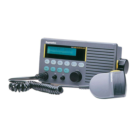
As a loudhailer, the RAY430 amplifies your voice up to a 30 watt level, for hailing through the hailing horn speaker, and when listening for replies, amplifies the incoming sounds to the desired listening level. -
Page 6: Specifications
EXTERNAL ALARM CONNECTION — For external systems or security alarm sensors. EASY TO USE — An ideal arrangement, the RAY430 has an illuminated keyboard and LCD which clearly shows all selected stations and operating modes. DURABLE, WATERPROOF CONSTRUCTION — With rugged gaskets and our heavy-duty microphone the RAY430 is built to survive in the toughest marine environments. -
Page 7: Installation
UNPACKING AND INSPECTION Use care when unpacking your new RAY430 from the shipping carton to prevent damage to the contents. It is also a good practice to save the carton and the interior packing material. The original packing material should be used in the unlikely event that it becomes necessary in the future to return the unit for service. -
Page 8: Optional Accessories
2.2.1 Optional Accessories Item # Console Mounting Kit (Flush Mount) Console Mounting Kit (Trim Ring Style) Power Supply, 115/220 VAC to 1 2 VDC STORAGE After all of the components have been unpacked and inspected, they should be replaced in their shipping containers and stored in a dry place until they are to be installed. -
Page 9: Planning The Installation
PLANNING THE INSTALLATION When planning the location for your RAY430 to be installed, the following conditions should be considered to insure dependable and trouble-free operation. 1) The mounting location should be easily accessible to allow easy operation of the front panel and provide the best viewing angle of the display. - Page 10 Figure 2-2 Outline and Mounting Dimensions...
-
Page 11: Mounting Options
DO NOT INSTALL THIS RADIO ON VESSELS WITH POSITIVE 2.5.1 DC Power Connections The RAY430 is intended for use on vessels with 12 VDC power systems and can operate as long as the DC supply is regulated between 10.8 and 16 VDC. -
Page 12: Intercom Speaker(S)
The power leads should normally be routed to the ship’s DC power distribution panel on larger boats. The RAY430 is fused at 10 amps so connection to a 10 amp or (maximum of) 15 amp circuit breaker is recommended. On smaller vessels the power leads may be connected directly to the main battery, isolation switch, or circuit breaker. -
Page 13: Hailer Horn(S)
This should be done to ensure optimum performance. Generally speaking the horn should be mounted as far away as possible and facing away from the RAY430 base unit. It should be pointed in the opposite direction of the RAY430 microphone as you are speaking into it. -
Page 14: Auxiliary Lnput
In situations where the main unit is distant from the operator and the noise level is very high, it may be difficult to hear your RAY430 clearly. By connecting an external (8 ohms, 5 watts or more) speaker, the sound level can be increased for improved listening capability. When an external speaker is connected at the external speaker jack, the internal speaker is automatically disconnected. - Page 15 Figure 2-8 RAY430 Electrical Connections...
- Page 16 2-10...
-
Page 17: Operation
INTRODUCTION While the operation of the RAY430 is easy and straight forward, the operator who is familiar with the functions and understands the layout of the front panel controls will be able to obtain the best performance from their equipment. - Page 18 Rotating this control clockwise will increase the listening volume at the internal speaker and rotating this control counterclockwise will decrease the volume. 4) Hail Key: Pressing the [HAIL] key puts the RAY430 into the hailer mode and HAILER is displayed on the LCD. 5) FOG (Foghorn) Key: Pressing the [FOG] key sequentially selects one of the 9 different horn or automatic fog signals for use.
-
Page 19: Lcd Display
The lighting can also be turned off by use of the On/Off & Dimmer control knob. The Ray430 has 4 operating modes. The selected mode is indicated by the message on the left side of the display. The modes messages are: HAILER —... - Page 20 When the FOG mode is selected, the message area will display the selected type of signal to be emitted as follows: TYPE MANUAL UNDRWY STOP SAIL ANCHOR AGROUND YELP ALARM The speaker station display normally indicates the location of the speakers selected for use with each operating function.
-
Page 21: Operating Procedures
Controls the volume level to external loudspeakers connected to the RAY430. 2) Listen Volume This allows the user to Adjust the RAY430 to the desired listening volume level. When the control is turned clockwise, the volume level will increase. The volume level decreases when... -
Page 22: Hail Mode
The mode keys are used to select one of the four operating modes. They are HAIL, FOG, AUX or INTC. To operate the RAY430 as a loudhailer, proceed as follows: 1. Press the [HAIL] key. After pressing the [HAIL] key, the HAIL mode is selected and “HAILER” appears on the LCD display in the operating mode window. - Page 23 Listen volume control knobs. Marking calls from Remote Intercom Stations As long as RAY430 power is on, the RAY430 master station can be called from any of the Inter-com sub-stations. When the [CALL] switch on the sub-station speaker is pressed, both an audible beeping and an LCD display indicator tell the master station which remote station wishes to communicate with the master station.
-
Page 24: Fog Horn Mode
3.3.5 Fog Horn Mode The [FOG] key allows the user to alternately select one of the automatic or manual FOG output signals. There are 9 kinds of alarms. They are: MANUAL, UNDRWY, STOP, SAIL, TOW, ANCHOR, AGROUND, YELP and ALARM. Whenever the [FOG] key is pressed, the alarm type is changed in the following order: A. - Page 25 In 1 second, “FOG 1 “ disappears and the station speaker selection appears. The Fog 1 alarm pattern is: One 5-second blast at 2 minute intervals. C. STOP (Fog 2) Usage: Power Boat “STOPPED” This automatic fog signal is emitted when the vessel is stopped. The message “STOP” appears in the mode display window and “FOG 2”...
- Page 26 “FOG 3” will disappear and the speaker station selection re-appears in the station display window. The Fog 3 signal pattern is: One 5 second blast, followed by two I second blast, at 2 second intervals, this will be repeated every 2 minutes. E.
- Page 27 F. ANCHOR (FOG 5) Usage: Any Vessel at Anchor For this automatic fog signal press the [FOG] key again, the message “ANCHOR” appears on the mode display and “FOG 5” appears in the station display window. “FOG 5” will disappear and the speaker station reappears in 1 second after FOG 5 is selected. The Fog 5 signal pattern is: A rapidly ringing bell tone will sound for a duration of at least 5 seconds, with a repetition interval which will not exceed 1 minute.
- Page 28 H. YELP Usage: Coast Guard, Patrol Vessels, etc. This is a manually activated attention getting alarm signal often used by regulatory vessels. When the [FOG] key is pressed again Yelp is selected, “Yelp” appears in the mode display window. In this mode the horn yelps by pressing the microphone PTT button. I.
-
Page 29: Aux Mode
OFE In this condition the burglar alarm will only sound if the ON signal from the external alarm sensor connected to the ALARM is tripped. Clearing the ALARM mode To disable the Burglar alarm mode, press the [FOG] key or turn off the RAY430 by rotating the On/Off & Dimmer control knob fully counterclockwise. 3.3.6 Aux Mode... - Page 30 3-14...
-
Page 31: Technical Description
SECTION 4 TECHNICAL DESCRIPTION BLOCK DIAGRAM Figure 4-1 is the block diagram of the RAY43O. The operation of the circuitry described below is based upon this block diagram. 1. 1. CPU The CPU (U-203) accepts key entry from the keyboard and selects the proper input and out- put signals to control devices. - Page 32 Selects input signal to active the FWD, AFT, INT, or EXT speaker(s). 10. 10. Tone Generator Generates a horn and alarm sound for the RAY430. This generator is controlled by the CPU to produce correct sound patterns and signal timing for various automatic or manual signal outputs.
- Page 33 Figure 4-1 RAY430 Block Diagram...
-
Page 35: Maintenance
5.1.1 Product and Customer Service In the event that your RAY430 is in need of service, the dealer from whom the radio was purchased, or an authorized Raymarine dealer. -
Page 36: Adjustment
Do not use solvents or other chemicals for cleaning this equipment. ADJUSTMENT The RAY430 has been completely aligned at the factory and normally does not require any readjustment at installation. However, it is possible to adjust the tone level of the Hail & Intercom signal. -
Page 37: Intercom Output Adjustment
5.3.3 Intercom Output Adjustment Connect Audio Oscillator; AC SSVM and 8-ohm Dummy Load as shown in Figure 5-2 (Audio Oscillator output: 7.5 mV). Rotate Hail Volume fully clockwise. Adjust VR302 for 6V on the AC SSVM. Figure 5- 2 Test connection of Intercom output Adjustment 5.3.4 Level Meter Adjustment Connect 8-ohm Dummy Load to FWD terminal. -
Page 39: Parts List
SECTION 6 ***** LINEAR A PCB ASSEMBLY SECTION ***** Description Linear A PCB Assembly Capacitors Stacked Metallized PPS Film, 0.001 µF Stacked Metallized PPS Film, 0.0033 µF Stacked Metallized PPS Film, 0.047 µF Stacked Metallized PPS Film, 0.1 µF Ceramic, 100 pF Ceramic, 0.047 µF Elec., 1 µF/50WV Elec., 2.2 µF/50WV... - Page 40 Description Resistors (cont.) Metal Glaze, 1 kohm Metal Glaze, 2.2 kohm Metal Glaze, 3.3 kohm Metal Glaze, 3.9 kohm Metal Glaze, 4.7 kohm Metal Glaze, 10 kohm Metal Glaze, 15 kohm Metal Glaze, 22 kohm Metal Glaze, 47 kohm Metal Glaze, 100 kohm Metal Glaze, 220 kohm Metal Glaze, 270 kohm Metal Glaze, 510 kohm...
- Page 41 Description Miscellaneous (cont.) Fiber, PCB ***** LINEAR B PCB ASSEMBLY SECTION ***** Linear B PCB Assembly Capacitors Stacked Metallized PPS Film, 0.001 µF Stacked Metallized PPS Film, 0.01 µF Ceramic, 100 pF Ceramic, 0.1 µF Elec., 10 µF/25WV Elec., 47 µF/25WV Elec., 220 µF/25WV Elec., 1000 µF/35WV Coil...
- Page 42 Description Semiconductors (cont.) Transistor, 2SA1298(Y) Transistor, 2SC4116(Y) Diode, 1N5401-B Diode, 1S1888A Miscellaneous Relay, ME-1-12P (12V DC) Connector, B26B-XADSS-N(LF)(SN) Connector, TX14-30R-10ST-N1E Connector, B5B-XH-A(LF)(SN) Connector, B4B-XH-A(LF)(SN) Terminal Block, M116C-24 ***** EL PCB ASSEMBLY SECTION ***** EL PCB Assembly Capacitors Stacked Metallized PPS Film, 0.0082 µF Elec., 1 µF/50WV Elec., 470 µF/25WV Coil...
- Page 43 Description ***** CPU PCB ASSEMBLY SECTION ***** CPU PCB Assembly Capacitors Stacked Metallized PPS Film, 0.01 µF Ceramic, 10 pF Ceramic, 0.1 µF Elec., 1 µF/50WV Elec., 4.7 µF/25WV Elec., 10 µF/16WV Elec., 100 µF/16WV Elec., 100 µF/25WV Resistors Metal Glaze, 10 ohm Metal Glaze, 100 ohm Metal Glaze, 1 kohm Metal Glaze, 2.2 kohm...
- Page 44 Description Semiconductors (cont.) Transistor, RN1410 LED, SLR-342MG3F Diode, 1SS226 I.C., SML-210MTT86 Miscellaneous EL Panel, GE-92D-9949A Crystal, SM1984JTR (20MHz) Volume, 10 kohm Switch (Push), SKRPABE010 Switch (Push), SMTE3-01-E-Z Switch (Slide), CFP-0202MB Connector, B26B-XADSS-N(LF)(SN) Connector, B20B-XADSS-N(LF)(SN) Connector, B2B-XH-A(LF)(SN) Connector, XG8S-0331 ***** CHASSIS ASSEMBLY SECTION ***** Bezel Assembly W/LCD Window Knob Dim/Hail LCD Spacer...
- Page 45 Description Qty. Symbol Side Chassis L Transformer Bracket Yoke Bracket Yoke Knob W/Screw Yoke Spacer Internal Speaker Heat Sink Rear Gasket Rear Terminal Block Knob Spacer Vol Spacer Heat Sink (IC-1) PCB Spacer LCD101 Part No. G263596-4 G263806-1 G261807-1 G263597-13 G263597-28 G263648-21 G263648-24...
-
Page 46: Assembly Drawing
6.2 ASSEMBLY DRAWING * = Not supplied with PCB Assembly Figure 6-1 See parts list for component part number Assembly Drawing... -
Page 47: Parts List For Assembly Drawing
6.3 PARTS LIST for ASSEMBLY DRAWING DESCRIPTION QTY. BEZEL ASSEMBLY KEY TOP (W/BEZEL ASSY) LCD SPACER LIGHT PIPE DIM/HAIL (W/BEZEL ASSY) KNOB DIM/HAIL KNOB LISTEN CABINET REAR REAR CHASSIS SIDE CHASSIS R SIDE CHASSIS L TRANSFORMER BRACKET HEAT SINK REAR GASKET REAR YOKE BRACKET YOKE KNOB W/SCREW... - Page 48 6.4 INTERNAL WIRING DRAWING Figure 6-2 Block Diagram 6-11...
-
Page 49: Linear A Schematic Diagram
6.5 LINEAR A SCHEMATIC DIAGRAM Figure 6-3 Schematic Diagram (Linear A Section) 6-12... -
Page 50: Linear B Schematic Diagram
6.6 LINEAR B SCHEMATIC DIAGRAM Figure 6-4 6-13 Schematic Diagram (Linear B Section) -
Page 51: Linear A Pcb Parts Layout
6.7 LINEAR A PCB PARTS LAYOUT 6.8 LINEAR B PCB PARTS LAYOUT TOP VIEW TOP VIEW BOTTOM VIEW BOTTOM VIEW Figure 6-5 Figure 6-6 Linear A PCB Linear B PCB Parts Layout Parts Layout 6-14... -
Page 52: Cpu Pcb Schematic Diagram
6.9 CPU PCB SCHEMATIC Figure 6-7 6-15 Schematic Diagram (Main Section) -
Page 53: Cpu Pcb Parts Layout
6.10 CPU PCB PARTS LAYOUT TOP VIEW BOTTOM VIEW TOP VIEW BOTTOM VIEW TOP VIEW BOTTOM VIEW Figure 6-8 CPU PCB Parts Layout 6-16 Figure 6-9 EL PCB Parts Layout Figure 6-10 Volume PCB Parts Layout...