Table of Contents
Advertisement
Alioth GE
Alioth PE
USER'S MANUAL
M/B For Socket 478 Pentium 4 Processor
NO. G03-845GEMAX1A
Release date: October 2002
Trademark:
* Specifications and Information contained in this documentation are furnished for information use only, and are
subject to change at any time without notice, and should not be construed as a commitment by manufacturer.
Advertisement
Table of Contents

Related Manuals for JETWAY ALIOTH


Summary of Contents for JETWAY ALIOTH
- Page 1 Alioth GE Alioth PE USER'S MANUAL M/B For Socket 478 Pentium 4 Processor NO. G03-845GEMAX1A Release date: October 2002 Trademark: * Specifications and Information contained in this documentation are furnished for information use only, and are subject to change at any time without notice, and should not be construed as a commitment by manufacturer.
-
Page 2: Table Of Contents
TABLE OF CONTENT USER’S NOTICE........................... ii MANUAL REVISION INFORMATION..................ii COOLING SOLUTIONS ......................ii CHAPTER 1 INTRODUCTION OF Alioth GE/ Alioth PE MOTHERBOARD FEATURE OF MOTHERBOARD..................1 SPECIFICATION ......................2 PERFORMANCE LIST ....................3 LAYOUT DIAGRAM & JUMPER SETTING ..............4 CHAPTER 2 HARDWARE INSTALLATION HARDWARE INSTALLATION STEPS................ -
Page 3: User's Notice
TRANSMITTED OR TRANSLATED INTO ANY LANGUAGE IN ANY FORM OR BY ANY MEANS WITHOUT WRITTEN PERMISSION OF MANUFACTURER. THIS MANUAL CONTAINS ALL INFORMATION REQUIRED TO USE Alioth GE/ Alioth PE MOTHER-BOARD AND WE DO ASSURE THIS MANUAL MEETS USER’S REQUIREMENT BUT WILL CHANGE, CORRECT ANY TIME WITHOUT NOTICE. -
Page 4: Chapter 1 Introduction Of Alioth Ge/ Alioth Pe Motherboard
Alioth GE/ Alioth PE Motherboard 1-1 Feature of motherboard The Alioth GE/ Alioth PE motherboard is design for use Intel Pentium 4 Processor in 478 Pin Package/Northwood Processor with the Intel 845GE/845PE Chipset delivers a high performance and professional desktop platform solution. Which utilize the Socket 478 design and the memory size expandable to 2.0GB. -
Page 5: Performance List
∗ Intel 845GE Graphics Memory Controller Hub (GMCH) Chipset Chipset for Alioth GE ∗ Intel 845PE Memory Controller Hub (MCH) Chipset for Alioth ∗ Intel 82801DB I/O Controller Hub (ICH4) Chipset ∗ Support Intel Pentium 4 478 Pin package utilizes Flip-Chip Pin... -
Page 6: Layout Diagram & Jumper Setting
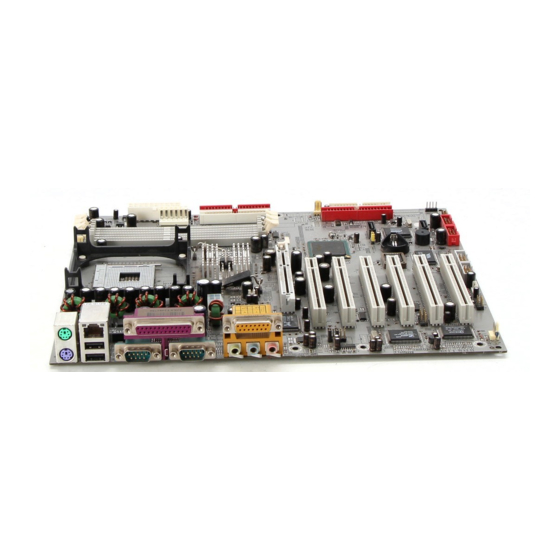
The following performance data list is the testing result of some popular benchmark testing programs. These data are just referred by users, and there is no responsibility for different testing data values gotten by users (the different Hardware & Software configuration will result in different benchmark testing results.) Performance Test Report CPU:... - Page 7 GAME/MIDI PORT PRINT PS/2 MOUSE PS/2 Keyboard LINE-IN COM1 VGA/COM2A LINE-OUT (Option) VGA (for Alioth GE) COM2A (for Alioth PE) ATX 12V Power Conn. K/B Power ON CPU Socket Jumper (JP1) PS2 KB/Mouse Port CPU FAN USB Port /LAN Connector ATX Power Conn.
- Page 8 34-pin Block P.13 IDE1/IDE2/IDE3 Primary/Secondary/Third IDE 40-pin Block P.14 Connector SATA1/SATA2 Serial-ATA Port Connector 7-pin Block P.15 Only for Alioth GE Headers Header Name Description Page COM2 (for Alioth GE) Serial Port COM2 Headers 9-pin Block P.15 AUDIO Line-In/Out, MIC Headers 9-pin Block P.15...
-
Page 9: Chapter 2 Hardware Installation
Hardware installation 2-1 Hardware installation Steps Before using your computer, you had better complete the following steps: 1. Check motherboard jumper setting 2. Install CPU and Fan 3. Install System Memory (DIMM) 4. Install Expansion cards 5. Connect IDE and Floppy cables, Front Panel /Back Panel cable 6. -
Page 10: Install Cpu
2. Forget password 3. After over clocking system boot fail 1-2 closed Normal (Default) 2-3 closed Clear CMOS CMOS RAM Clear Setting (3) Keyboard Power On function Enabled/Disabled: JP1 When setting Enabled you can using keyboard by key in password to power on system. 1-2 closed K/B Power ON Disable 2-3 closed K/B Power ON Enabled... -
Page 11: About Intel Pentium 4 478-Pin Cpu
LAN (interface) - Local Area Network - the interface to your local area network. BIOS (Basic Input/Output System) - the program logic used to boot up a computer and establish the relationship between the various components. Driver - software, which defines the characteristics of a device for use by another device or other software. -
Page 12: Expansion Card
This motherboard provides three 184-pin DUAL INLINE MEMORY MODULES (DIMM) sites for memory expansion available from minimum memory size of 64MB to maximum memory size of 2.0GB DDR SDRAM. Valid Memory Configurations Bank 184-Pin DIMM Total Memory Bank 0, 1 (DDR1) DDR200/DDR266/DDR333 64MB∼1.0GB DDR SDRAM Module... -
Page 13: Procedure For Expansion Card Installation
1. Read the documentation for your expansion card and make any necessary hardware or software setting for your expansion card such as jumpers. 2. Remove your computer’s cover and the bracket plate on the slot you intend to use. 3. Align the card’s connectors and press firmly. 4. -
Page 14: Agp Slot
IMPORTANT! If using PCI cards on shared slots, make sure that the drivers support “Shared IRQ” or that the cards don’t need IRQ assignments. Conflicts will arise between the two PCI groups that will make the system unstable or cards inoperable. 2-5-4 AGP Slot This motherboard provides an AGP Slot, only support the 1.5V 4X AGP VGA card. - Page 15 Pin 1 ROW2 ROW1 3.3V 3.3V -12V 3.3V Soft Power On Power OK +5V (for Soft Logic) +12V (2) ATX 12V Power Connector (4-pin block) : ATX12V This is a new defined 4-pins connector that usually comes with ATX Power Supply. The ATX Power Supply which fully support Pentium 4 processor must including this connector for support extra 12V voltage to maintain system power consumption.
- Page 16 Microphone Connector Game/MIDI : For joystick or MIDI Device (9) VGA Connector (15-pin D-Sub) Connector: VGA (for Alioth GE only) VGA is the 15-pin D-Subminiature female connector for display monitor. (10) Serial Port COM1/COM2: COM1/COM2A (COM2A only for Alioth PE) COM1/COM2A is the 9-pin D-Subminiature mail connector.
- Page 17 IDE1 Pin 1 Primary IDE Connector (13) Secondary IDE Connector (40-pin block): IDE2 This connector connects to the next set of Master and Slave hard disks. Follow the same procedure described for the primary IDE connector. You may also configure two hard disks to be both Masters using one ribbon cable on the primary IDE connector and another ribbon cable on the secondary IDE connector.
-
Page 18: Headers
Pin 1 SATA2 SATA1 Serial-ATA Port Connector 2-6-2 Headers Serial Port2 COM2 Header (9-pin) : COM2 (only for Alioth GE) C O M2 Note: Orient the read marking on the COM2 ribbon cable to pin 1 Pin 1 Serial Port2 COM2 Header Line-In/Out, MIC Header (9-pin): AUDIO This header connect to Front Panel Line-In, Line-out, MIC connector with cable. - Page 19 1394 Port Headers (9-pin): 1394A, 1394B 1394A 1394B Pin 1 Pin 1 1394 Port Headers IDE Activity LED: IDE LED This connector connects to the hard disk activity indicator light on the case. Reset switch lead: RESET This 2-pin connector connects to the case-mounted reset switch for rebooting your computer without having to turn off your power switch.
- Page 20 Wake-On-LAN Headers (11) FAN Speed Headers (3-pin) : SYSFAN1, SYSFAN2, CPUFAN These connectors support cooling fans of 350mA (4.2 Watts) or less, depending on the fan manufacturer, the wire and plug may be different. The red wire should be positive, while the black should be ground.
-
Page 21: Starting Up Your Computer
2-7 Starting Up Your Computer 1. After all connection are made, close your computer case cover. 2. Be sure all the switch are off, and check that the power supply input voltage is set to proper position, usually in-put voltage is 220V∼240V or 110V∼120V depending on your country’s voltage used. -
Page 22: Chapter 3 Introducing Bios
Chapter 3 Introducing BIOS The BIOS is a program located on a Flash Memory on the motherboard. This program is a bridge between motherboard and operating system. When you start the computer, the BIOS program gain control. The BIOS first operates an auto-diagnostic test called POST (power on self test) for all the necessary hardware, it detects the entire hardware device and configures the parameters of the hardware synchronization. -
Page 23: The Main Menu
3-3 The Main Menu Once you enter Award BIOS CMOS Setup Utility, the Main Menu (Figure 3-1) will appear on the screen. The Main Menu allows you to select from fourteen setup functions and two exit choices. Use arrow keys to select among the items and press <Enter> to accept or enter the sub-menu. -
Page 24: Standard Cmos Features
Load Optimized Defaults Use this menu to load the BIOS default values that are settings for optimal performances system operations. Load Standard Defaults Use this menu to load the BIOS default values that are factory settings for the stable performance system operation. Set Supervisor/User Password Use this menu to set User and Supervisor Passwords. -
Page 25: Advanced Bios Features
Time The time format is <hour><minute><second>. Primary Master/Primary Slave Secondary Master/Secondary Slave Press PgUp/<+> or PgDn/< – > to select Manual, None, Auto type. Note that the specifications of your drive must match with the drive table. The hard disk will not work properly if you enter improper information for this category. - Page 26 Anti-Virus Protection Allows you to choose the VIRUS Warning feature for IDE Hard Disk boot sector protection. If this function is enabled and someone attempt to write data into this area, BIOS will show a warning message on screen and alarm beep. Disabled (default) No warning message to appear when anything attempts to access the boot sector or hard disk partition table.
-
Page 27: Advanced Chipset Features
Typematic Rate Setting Keystrokes repeat at a rate determined by the keyboard controller. When enabled, the typematic rate and typematic delay can be selected. The settings are: Enabled/Disabled. Typematic Rate (Chars/Sec) Sets the number of times a second to repeat a keystroke when you hold the key down. The settings are: 6, 8, 10, 12, 15, 20, 24, and 30. -
Page 28: Dram Timing Settings
Video RAM Cacheable Select Enabled allows caching of the video BIOS, resulting in better system performance. However, if any program writes to this memory area, a system error may result. The settings are: Enabled and Disabled. Memory Hole At 15M-16M You can reserve this area of system memory for ISA adapter ROM. -
Page 29: Integrated Peripherals
CMOS Setup Utility – Copyright(C) 1984-2002 Award Software Integrated Peripherals > Onboard IDE Function Press Enter Item Help > Onboard Device Function Press Enter > Onboard Super IO Function Press Enter USB2.0 Controller Enabled Menu Level > Init Display First PCI Slot Power On Function Button Only... -
Page 30: Onboard Device Function
The integrated peripheral controller contains an IDE interface with support for two IDE channels. Select Enabled to activate each channel separately. The settings are: Enabled and Disabled. Primary/Secondary Master/Slave PIO The four IDE PIO (Programmed Input/Output) fields let you set a PIO mode (0-4) for each of the four IDE devices that the onboard IDE interface supports. -
Page 31: Onboard Super Io Function
CMOS Setup Utility – Copyright(C) 1984-2002 Award Software Onboard Super IO Function Onboard FDD Controller Enabled Item Help Onboard Serial Port 1 3F8/IRQ4 Onboard Serial Port 2 2F8/IRQ3 UART2 Mode Select Normal Menu Level >> RxD, TxD Active Hi, Lo IR Transmission Delay Enabled IR Duplex Mode... -
Page 32: Power Management Setup
The Power Management Setup allows you to configure your system to most effectively save energy saving while operating in a manner consistent with your own style of computer use. CMOS Setup Utility – Copyright(C) 1984-2002 Award Software Power Management Setup ACPI Function Enabled Item Help... -
Page 33: Pm Timer Reload Events
use this function. During Enabled, choose the Date and Time Alarm: Date(of month) Alarm You can choose which month the system will boot up. Set to 0, to boot every day. Time(hh:mm:ss) Alarm You can choose what hour, minute and second the system will boot up. Note: If you have change the setting, you must let the system boot up until it goes to the operating system, before this function will work... -
Page 34: Irq Resources
Data (ESCD) when you exit Setup if you have installed a new add-on and the system reconfiguration has caused such a serious conflict that the operating system can not boot. The settings are: Enabled and Disabled. Resource Controlled By The Award Plug and Play BIOS has the capacity to automatically configure all of the boot and Plug and Play compatible devices. -
Page 35: Pc Health Status
CMOS Setup Utility – Copyright(C) 1984-2002 Award Software PC Health Status Shutdown Temperature Disabled Item Help CPU Warning Temperature Disabled Show PC Health in Post Enabled 25 ° C Current System Temperature 38 ° C Current CPU Temperature Menu Level > Current CPUFAN Speed 5000 rpm Current SYSFAN Speed... -
Page 36: Load Standard/Optimized Defaults
Spread Spectrum This item allows you to set the CPU Host/PCI clock and Spread Spectrum. The settings are: Enabled, Disabled. Host/PCI Clock at Next Boot This item allows you to select CPU frequency step by step increasing. The choice are: 100MHz∼200MHz DRAM Clock at Next Boot is This item allows you select the DRAM Clock same as Host clock, or can add 33MHz when 100MHz/133MHz. -
Page 37: Set Supervisor/User Password
setup menus. When you select this function, the following message will appear at the center of the screen to assist you in creating a password. ENTER PASSWORD: Type the password, up to eight characters in length, and press <Enter>. The password typed now will clear any previously entered password from CMOS memory. -
Page 38: Magic Install Supports Windows 98Se/Me/Nt4.0/2000/Xp
From MAGIC INSTALL MENU you may make 12 selections: 1. INF install Intel 845 chipset system driver 2. VGA install Intel 845G VGA driver (Only for Alioth GE) 3. SOUND install CMI8738-6CH Audio driver 4. LAN install RT8100 LAN Controller driver 5. -
Page 39: Inf Install Intel 845 Chipset System Driver
NOTE: MAGIC INSTALL will auto detect file path X:\INTEL845\INF\SETUP.EXE This driver supports WINDOWS 98SE/ME/2000/XP (NT4.0 do not require) 4-2 VGA install Intel 845G VGA Driver (Only for Alioth GE) 1. Click VGA when MAGIC INSTALL MENU Click NEXT When Intel (R) Brookdale-G-... -
Page 40: Sound
Click YES, This is Announce CopyRight 4. If You Want Re-start Computer , Click FINISH 4-3 SOUND Install CMI8738/C3DX PCI Audio Driver 1. Click SOUND when MAGIC INSTALL 2. Click Install Device Driver and Applications MENU appears 3. Choose Setup Language and Click OK 4. - Page 41 7. Select 2/4/5.1 Channel speaker output and 8. Click YES and restart computer Click EXIT 9. C-Media Audio Rack Play table 10. Select Start\Program\PCI Audio Application\ Multi-Channel Audio Demo, Test 6CH Speaker position 11. Select C-Media Mixer\Advanced\Speakers , 12. Enable USING Xear 3D, you can select 4/6 this is C-Media Audio speaker Configuration Speakers Xear Function setting .
-
Page 42: Lan Install Rtl8100 Lan Controller Driver
4-4 LAN Install RTL8100 LAN Controller Driver The path of the file: for WINDOWS 98SE is X:\RTLLAN\WIN98 for WINDOWS 98ME is X:\RTLLAN\WINME for WINDOWS NT4.0 is X:\RTLLAN\WINNT4 for WINDOWS 2000 is X:\RTLLAN\WIN2000 for WINDOWS XP is X:\RTLLAN\WINXP WINDOWS 98SE/98ME/2000/XP Setup 1. -
Page 43: Pc-Health Intel 845 Pc-Health Monitor
3. Click Yes to Restart your computer after Driver Install Finish The path of the file: For Windows 9X is X:\SATA375\WIN98-ME (including Win95/98/ME) For Windows NT4.0 is X:\SATA375\NT4 For Windows 2000 is X:\SATA375\WIN2000 For Windows XP is X:\SATA375\WINXP When you use Serial ATA install Window NT4.0/2000/XP OS, Please insert Serial ATA DISK from A:\ , and Press F6 key install driver firest 4-6 PC-HEALTH Intel 845 PC-Health Monitor The path of the file is X:\INTEL845\HW30\SETUP.EXE (Only support WINDOWS 98SE/ME) -
Page 44: How To Utilize Pc-Health
4-6-1 How To Utilize PC-HEALTH 1. Click Program → Winbond Hardware Doctor 2. After executing Winbond Hardware Doctor it → Hardware Doctor the Winbond Hardware supports system voltage, Fan speed and Doctor will appears CPU/SYSTEM Temperature. Because this is You can remove the Utility in Control Panel a On-time Monitoring program therefore the →... - Page 45 3. After finish Setup you will have a Magic 4. Double click the Magic BIOS icon you will BIOS icon in your screen have this picture, choose from internet you can upgrade BIOS On-line 5. When On-line update BIOS the program will 6.
-
Page 46: Iaa Install Intel Application Accelerator Software
4-8 IAA Install Application Accelerator Software The Intel Application Accelerator is designed to improve performance of the storage sub-system and overall system performance. This software delivers improved performance through several ingredient technologies (components). Certain components will be available only on Pentium ... -
Page 47: How To Install Usb 2.0 Driver
5. Click INSTALL, Start to install the software 6. Setup Complete and click FINISH 7. After PC-CILLIN 2002 complete, Please 8. finish register process, we recommend select register your information and get LICENSE update item ro download newest engine code KEY from TREND MICRO web site, enter and virus code your license key and click FINISH... -
Page 48: How To Disable On-Board Sound
You may copy from DRIVER CD X:\FLASH\AWDFLASH.EXE or download from our web site. STEP 3. Copy latest BIOS for Alioth GE/ Alioth PE from our web site to your boot disc. STEP 4. Insert your boot disc into A:, start the computer, type “Awdflash A:\845GEMAXAxxx.BIN /SN/PY/CC/R”...